




Startseite
-
Blog & Neuigkeiten
-
LCD Display Connector Failure Modes: ZIF Lock, FPC Cable, Solder Joint, and Contact Wear
LCD Display Connector Failure Modes: ZIF Lock, FPC Cable, Solder Joint, and Contact Wear
2026-07-08
11:59
LCD Display Connector Failure Modes: ZIF Lock, FPC Cable, Solder Joint, and Contact Wear
A Field Repair and Engineering Diagnostic Reference
Vom technischen Team von Kadi Display | www.kadidisplay.com
Introduction: The Weakest Link in Every LCD Module
Ask any field technician what fails first on an LCD display module, and the answer is rarely the glass, the backlight LEDs, or the driver IC. It’s the connector. The interface between the panel and the host PCB — whether a ZIF (Zero Insertion Force) socket, a soldered FPC tail, or a board-to-board connector — concentrates more mechanical stress, more repeated handling, and more environmental exposure than almost any other component in the display assembly.
This is not a minor concern. Connector and flex-cable related issues are consistently cited among the top categories of field returns for display modules across consumer electronics, automotive, and industrial equipment repair channels. A single ZIF connector lock might be cycled dozens of times across a product’s service or repair history; a single 0.5 mm pitch FPC pad might carry signal currents through a contact area smaller than a grain of rice. Understanding exactly how these interfaces fail — mechanically, electrically, and chemically — is essential for anyone doing display repair, field diagnostics, or new product design.
This article breaks down LCD connector failure into four major categories: ZIF lock mechanical failure, FPC cable degradation, solder joint failure, and contact wear/oxidation. Each section includes the failure mechanism, diagnostic signs, and repair or design guidance.
Understanding the Connector Landscape: ZIF, FPC, and Board-to-Board
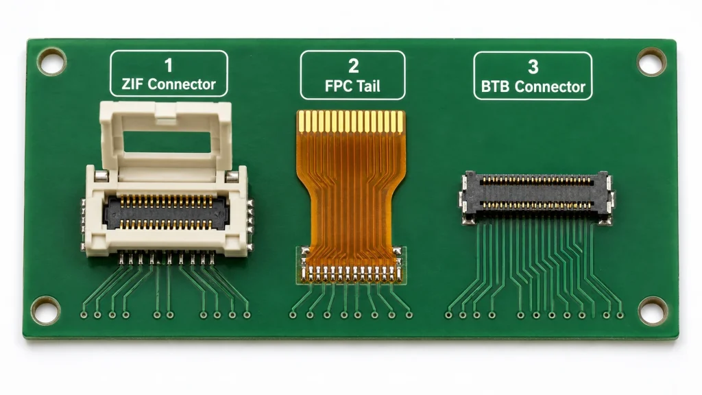
Before diagnosing a failure, it helps to know what’s actually inside the connection. Three interface types dominate LCD module design.
ZIF (Zero Insertion Force) connectors
These use a movable flip-lock or slide-lock mechanism. The FPC tail is inserted into an open socket with no resistance, and the lock is then closed, applying clamping force to establish contact between the gold-plated FPC pads and the connector’s spring contacts. ZIF connectors are favored because they allow tool-free, low-damage-risk cable insertion — but the lock mechanism itself is a moving mechanical part, and moving parts wear out.
Soldered FPC tails
These skip the connector entirely; the flex cable’s gold-finger pads are soldered directly onto PCB pads using reflow or hot-bar soldering. This eliminates the mechanical lock failure mode entirely but makes the connection permanent and unrepairable without specialized rework equipment — a significant consideration for field-serviceable equipment.
Board-to-board (BTB) connectors
These mate two rigid PCBs directly using a male/female pin header pair, commonly used where the display PCB and main control board are stacked or adjacent rather than connected via flex cable.
Each interface type carries a distinct failure profile, which we’ll walk through below.
ZIF Lock Mechanical Failure: Cracked Latches and Lost Clamping Force
The ZIF connector’s flip-lock or slide-lock is a small, often brittle, plastic component — typically molded from LCP (Liquid Crystal Polymer) or similar high-temperature engineering plastic. It is also, in practical field experience, the single most common point of physical breakage during LCD module repair and replacement.
Common ZIF lock failure modes
Latch fracture from over-rotation: flip-lock ZIF connectors are designed to rotate through a specific angular range — typically 90 to 120 degrees from open to closed. Forcing the lock past its designed travel, or prying it open with a tool instead of fingers, frequently snaps the hinge pins, which are often less than 0.3 mm in diameter on compact 0.5 mm and 0.3 mm pitch connectors.
Repeated-cycle fatigue: ZIF connectors are typically rated for a finite number of mating cycles — commonly in the range of 20 to 50 cycles for low-cost consumer-grade connectors, though some industrial-grade ZIF sockets are rated higher. Each open-close cycle flexes the lock material slightly. In repair-heavy environments, this fatigue limit can be reached far sooner than in normal end-product use.
Incomplete lock engagement: a lock that appears closed but hasn’t fully seated will not apply adequate contact pressure on the FPC pads. This produces an intermittent connection that can be temperature- or vibration-sensitive — the display may work perfectly on the bench but fail intermittently once installed in an enclosure subject to thermal expansion or mechanical vibration.
Diagnostic approach
- Visually inspect the lock for hairline cracks, especially at the hinge points, using magnification (10x loupe or microscope).
- Gently test lock rigidity — a properly functioning lock should close with a distinct, firm resistance and stay closed under light tension. A loose or unstable close suggests fatigue or cracking.
- If the display shows intermittent flicker, partial image, or color shifts that change when the connector area is pressed or flexed, suspect incomplete lock engagement before assuming a panel-level fault.
Repair and prevention
ZIF connectors are generally not field-repairable once the lock mechanism is physically broken; replacement of the connector (requiring desoldering and resoldering on the host PCB) is usually the only fix. For new designs and repeated-test environments, specifying connectors with a documented higher mating-cycle rating, or switching to soldered FPC tails for applications where the connector will not need disassembly after final assembly, meaningfully reduces this failure mode.
FPC Cable Degradation: Cracking, Delamination, and Trace Fracture
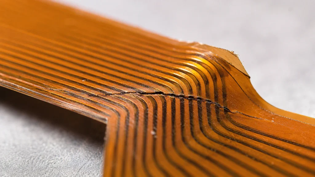
The flex cable itself — typically a polyimide substrate with copper traces and a protective coverlay — is engineered to survive repeated bending, but it is not infinite-life under all conditions. Understanding its construction clarifies why and where it fails.
Construction basics relevant to failure analysis
A typical LCD FPC has a base thickness around 0.1 mm for the bendable signal-routing section, with copper traces (commonly 0.5 oz or 1 oz rolled annealed copper) bonded to a polyimide substrate. In the connector contact area, the FPC is reinforced with a stiffener — FR4 or additional PI layers — bonded on, increasing the thickness in that zone to roughly 0.3 mm to match ZIF connector specifications and prevent the contact area from flexing.
Primary degradation mechanisms
Dynamic bend fatigue: FPCs used in repeatedly-folding applications are rated for a specific bend-cycle life. Rolled annealed (RA) copper traces on a polyimide substrate are commonly rated to withstand on the order of 50,000+ dynamic bend cycles in well-engineered designs, though this figure varies significantly with bend radius, trace width, and copper thickness. Bending tighter than the design’s minimum bend radius — commonly specified at a minimum of around 1.0 mm for the flex zone — dramatically accelerates crack initiation in the copper traces.
Static fold stress at installation: many LCD modules require the FPC to be folded once during assembly (a 180-degree fold to tuck the cable behind the panel). If this fold is made too close to the connector contact area, or with too tight a radius, it can initiate micro-cracks immediately, even though the cable may continue to function until vibration or thermal cycling propagates the crack into a full open circuit.
Delamination between copper and substrate: adhesive bonding the copper layer to the polyimide substrate can degrade under prolonged heat or humidity exposure, allowing the copper trace to lift slightly from its substrate. This doesn’t immediately break the circuit but reduces mechanical support for the trace.
Trace fracture from repeated micro-vibration: in automotive and industrial equipment, sustained low-amplitude vibration over months or years can fatigue-crack copper traces even without any visible bending — a failure mode that’s notoriously difficult to diagnose because the cable looks physically intact.
Diagnostic signs of FPC degradation
- Display shows partial image loss, missing color channels, or vertical/horizontal line dropouts that correlate with specific signal traces.
- Intermittent failures that worsen when the cable is flexed or when the device is subjected to vibration or temperature change.
- Visual inspection under magnification reveals discoloration, coverlay lifting, or visible crack lines at fold points — most commonly right at the edge of the connector stiffener.
For display modules in repeated-flex or vibration-prone applications, see Kadi Display’s overview of FFC vs. FPC flexible cable technology, which covers the construction differences relevant to selecting the right flex interconnect for a given mechanical environment.
Solder Joint Failure: Cold Joints, Fatigue Cracks, and Thermal Cycling Damage
When an FPC is soldered directly to the host PCB rather than connected via a ZIF socket, the failure profile shifts from a mechanical lock problem to a solder joint reliability problem — a well-studied area in electronics manufacturing with established failure statistics.
Common solder joint failure modes
Cold joints from manufacturing defects: a cold solder joint forms when insufficient heat is applied during the reflow or hot-bar soldering process, resulting in a joint that looks acceptable visually but has poor or partial metallurgical bonding. Cold joints often pass initial functional testing but fail intermittently in the field once subjected to thermal cycling or mechanical stress.
Thermal fatigue cracking: solder joints subjected to repeated thermal expansion and contraction accumulate fatigue damage at the joint interface over time. For FPC-to-PCB solder joints specifically, the differing coefficients of thermal expansion between the rigid PCB, the solder, and the flexible polyimide substrate concentrate mechanical stress directly at the solder fillet, making this joint type more susceptible to fatigue cracking than typical rigid-to-rigid component solder joints.
Lead-free solder embrittlement: since the industry-wide transition to lead-free (typically SAC305, tin-silver-copper) solder alloys, lead-free joints can be more prone to certain brittle fracture modes under mechanical shock compared to traditional tin-lead solder, particularly when joint geometry or cooling profile during manufacturing isn’t well controlled.
Pad lifting and trace damage during rework: attempting to manually reflow or desolder an FPC-to-PCB joint without proper hot-bar or hot-air rework equipment frequently lifts the copper pad off the PCB substrate or damages the delicate FPC gold-finger area.
Diagnostic approach
- Visual inspection under magnification for dull, grainy, or cracked solder surfaces versus the smooth, shiny appearance of a properly formed joint.
- Gentle mechanical flex testing near the joint, while monitoring the display for flicker or dropout, can reveal marginal joints — done carefully to avoid causing additional damage.
- X-ray inspection, where available, can reveal internal joint voids or cracks not visible from the surface — standard practice in high-reliability manufacturing quality control.
Repair considerations
Reworking FPC solder joints requires hot-bar reflow equipment or precision hot-air stations with proper temperature profiling; using a standard soldering iron on these fine-pitch joints carries a high risk of lifting pads or damaging adjacent traces. For field repair scenarios without access to proper rework tools, replacing the entire display module is usually the more reliable outcome.
Contact Wear and Oxidation: The Slow, Invisible Failure
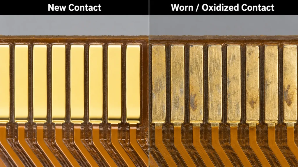
Unlike a cracked lock or a fractured trace, contact wear is gradual and often invisible to casual inspection — which makes it one of the most frequently misdiagnosed connector failures, often mistaken for a panel or driver IC fault.
The physics of contact wear
ZIF and FPC connector contacts rely on a thin layer of gold plating — typically just a few microns thick — over a base metal (commonly phosphor bronze for the spring contact, or copper for the FPC pad) to provide a stable, low-resistance, corrosion-resistant electrical interface. Each insertion cycle causes microscopic mechanical wear (fretting) at the contact interface as the gold-plated surfaces slide against each other under spring pressure.
Contact current rating context
Small-pitch FPC/ZIF contacts are typically rated for relatively low current per pin — often around 0.3 to 0.5 A maximum per contact in compact 0.5 mm pitch connector designs — meaning that signal integrity, not raw current capacity, is usually the limiting factor for display interface reliability rather than thermal overload.
Wear-through and base metal exposure
Once repeated insertion cycles wear through the thin gold plating layer, the underlying base metal becomes exposed. Phosphor bronze and copper both oxidize on exposure to air and humidity, forming a thin non-conductive or semi-conductive oxide layer at exactly the point of electrical contact. This is the mechanism behind a large share of ‘intermittent display’ complaints in repeatedly-serviced equipment — particularly on high-speed differential pairs used in interfaces like MIPI DSI or LVDS, where even small impedance mismatches or resistance increases can cause visible artifacts.
Environmental acceleration factors
- Humidity and salt exposure dramatically accelerate base-metal oxidation once gold plating is breached — a significant concern for outdoor, marine, or coastal-deployed equipment.
- Sulfur-containing environments (industrial, certain manufacturing facilities) can cause more aggressive tarnishing of exposed copper and bronze contacts.
- Repeated thermal cycling can cause micro-movement at the contact interface even without physical reinsertion, gradually abrading the plating through a mechanism similar to normal insertion wear.
Diagnostic signs
- Intermittent display issues — flicker, color shift, partial dropout — that seem to resolve temporarily after reseating the connector, then gradually return over days or weeks.
- Visible discoloration (brownish or dull gray tarnish) on contact pads under magnification, especially concentrated at the specific point where the spring contact rides on the pad.
- Issues that worsen in humid conditions or improve temporarily after the connector area is cleaned with isopropyl alcohol and a non-abrasive contact cleaning tool.
Prevention and best practice
- Avoid unnecessary connector cycling in field-serviceable equipment; each insertion is a wear event, even if minor.
- For applications expecting frequent disconnection/reconnection, specify connectors rated for a higher mating-cycle count and thicker gold plating where available.
- In humid or corrosive environments, sealed connector housings or conformal coating around (not on) the contact area can meaningfully extend service life.
Comparative Quick Reference: Connector Failure Modes
General Field Diagnostic Workflow for Suspected Connector Failure
When an LCD display shows symptoms that could be connector-related — flicker, partial image, intermittent dropout, or complete failure that seems sensitive to physical handling — a structured approach avoids unnecessary panel or driver replacement when the real fault is at the interface.
- Visual inspection: examine the ZIF lock, FPC tail, and solder joints (if accessible) under at least 10x magnification before powering on. Look for cracks, discoloration, lifted coverlay, or visibly incomplete lock engagement.
- Mechanical sensitivity test: with the display powered and showing the fault, gently press, flex, or wiggle the connector area (without disconnecting anything) and observe whether the symptom changes.
- Reseat and inspect: if accessible, carefully disconnect and reconnect the FPC, inspecting the contact pads and connector lock during the process. Note any resistance, looseness, or visible wear.
- Continuity and resistance testing: where test points are accessible, a multimeter continuity check or low-resistance measurement across suspect contacts can confirm a high-resistance or open connection that visual inspection alone might miss.
- Environmental correlation: note whether the fault correlates with temperature, humidity, or vibration conditions — this often points toward thermal fatigue (solder), bend fatigue (FPC), or oxidation (contact wear) rather than a one-time mechanical failure.
Designing for Connector Reliability from the Start
The most cost-effective way to reduce connector-related field failures is addressing them at the design and component-selection stage rather than relying on field repair.
Key design considerations include specifying ZIF connectors with mating-cycle ratings appropriate to the expected service and rework frequency, maintaining FPC bend radius well above the minimum specification throughout the cable routing path, keeping any required folds away from the stiffened connector contact zone, and selecting industrial-grade FPC materials — such as rolled annealed copper rather than standard etched copper — for applications expecting significant vibration or thermal cycling exposure.
For engineers sourcing display modules for industrial, automotive, or other high-duty-cycle applications, Kadi Display’s guidance on choosing the best industrial TFT LCD for embedded devices covers interface and reliability considerations relevant to this kind of evaluation.
Their broader embedded display selection resources cover resolution, brightness, and lifecycle factors alongside connector and interface reliability.
Schlussfolgerung
LCD connector failure is rarely a single, simple event — it’s usually the cumulative result of mechanical cycling, thermal stress, or environmental exposure acting on a component engineered for a specific service life. ZIF lock fractures come from exceeding designed mating cycles or rotation limits; FPC cables crack from bend-radius violations or vibration fatigue; solder joints fail from cold-joint defects or thermal fatigue; and contacts wear through gold plating into oxidation-prone base metal after repeated insertion.
Recognizing the specific failure signature of each mode — and resisting the instinct to immediately blame the panel or driver electronics when a display misbehaves intermittently — saves significant diagnostic time in both repair and new product development contexts. For new designs, selecting connectors, flex materials, and solder processes rated appropriately for the application’s expected mechanical and thermal environment remains the most reliable way to prevent these failures from reaching the field in the first place.
For industrial display modules engineered with reliability-rated connectors, FPC interfaces, and long-service-life construction, visit Kadi Anzeige — a Shenzhen-based manufacturer with over 20 years of experience in high-reliability industrial, medical, and embedded TFT LCD modules.
Vorherige
How to Choose FFC/FPC Connectors for Industrial Touchscreen Products
Nächster
Industrial LCD Failure Modes: Image Retention, Burn-in, Mura, Spot Damage and Backlight Aging
Hinterlasse einen Kommentar

Neueste Blog & Nachrichten
- Industrial LCD EOL: What Happens from Pre-Announcement to Replacement Mass Production?
- Electronic Component Obsolescence Management for Industrial Displays: An OEM Guide
- How to Develop a Production Ready Custom Display Assembly TFT Module Touch Cover Glass FPC Bonding and Mounting
- 15 Pin vs 22 Pin Raspberry Pi DSI Connectors Cable Pinout and Compatibility
- Native MIPI DSI vs LVDS or HDMI Bridge: An OEM Display Architecture Decision Guide

