




Startseite
-
Blog & Neuigkeiten
-
MIPI DSI Display Compatibility Checklist: 10 Specifications to Match with Your Host Processor Before Ordering
MIPI DSI Display Compatibility Checklist: 10 Specifications to Match with Your Host Processor Before Ordering
2026-07-24
18:24

A MIPI DSI connector on both the processor board and display does not automatically make the two devices compatible. Before ordering a sample, engineers should verify the MIPI DSI host, PHY, lane configuration, bandwidth, display timing, operating mode, pinout, power sequence, software support, and touch interface.
The purpose of this MIPI DSI display compatibility checklist is to determine whether a display is directly compatible, requires hardware or software modifications, or needs a different interface architecture. Completing these checks before purchasing can reduce unsuitable samples, PCB revisions, and delays during display bring-up.
Why a MIPI DSI Label Alone Does Not Confirm Compatibility
The MIPI Alliance defines MIPI DSI as a high-speed serial interface between a host processor and a display module. The specification provides a common communication framework, but it does not make every MIPI DSI panel interchangeable with every MIPI DSI processor.
Two devices may both support MIPI DSI and still differ in:
- PHY implementation
- Number of data lanes
- Supported lane rate
- Video timing
- DSI operating mode
- Pixel format
- Connector pinout
- Power and reset requirements
- Panel initialization
- Operating-system support
Compatibility must therefore be evaluated at four levels: physical connection, electrical and signal configuration, software support, and complete-system operation.
Specifications 1–3: Confirm the Host Controller, Lane Count, and Bandwidth
Does the Processor Have a Usable MIPI DSI Host?
Start with the complete processor or SoC part number. Do not rely on a product description that only says the device “supports MIPI.”
First confirm that the available interface is MIPI DSI rather than MIPI CSI. DSI connects a host processor to a display, while CSI is intended for cameras and imaging devices. A camera connector cannot be treated as a display output simply because both interfaces may use a similar physical layer.
Next, check whether:
- The processor contains a MIPI DSI host controller.
- The required DSI interface is enabled in the selected processor variant.
- The board routes the DSI signals to an accessible connector.
- The interface is available rather than assigned to another peripheral.
- The board support package supports the DSI controller.
- The processor and display use a compatible PHY.
The processor datasheet describes what the silicon can support, but the mainboard schematic or hardware manual confirms what is actually available on the board. A processor may include DSI capability even when a particular board does not route it to a usable connector.
Do the Host and Display Support the Same Lane Count?
A MIPI DSI link typically includes a clock lane and one or more data lanes. The display specification may require one, two, or four data lanes, while the host controller may support a different maximum or a limited set of configurations.
Check:
- The number of data lanes required by the display.
- The number of lanes supported by the host.
- Whether the host can be configured for the required lane count.
- Whether the selected lane count is supported by the board layout.
- Whether the panel initialization or software driver assumes a fixed configuration.
A four-lane host does not automatically support every one- or two-lane display. The controller, board routing, panel configuration, and driver must all support the selected arrangement.
Is the Available Lane Rate High Enough?
Lane count alone is not enough. The link must provide sufficient bandwidth for the required resolution, refresh rate, color depth, and blanking intervals.
Bandwidth requirements increase with:
- Higher horizontal and vertical resolution
- Higher refresh rates
- RGB888 rather than lower-bit-depth formats
- Longer horizontal or vertical blanking periods
- Additional protocol overhead
Compare the display’s required data rate with the host controller’s supported lane rate. Do not assume that a processor can drive a display simply because both support four lanes.
When bandwidth is marginal, possible options may include lowering the refresh rate, changing the pixel format, adjusting blanking parameters within the panel’s permitted range, or selecting a different display. These changes must be checked against both the panel specification and the host controller documentation.
Specifications 4–5: Match Display Timing, Operating Mode, and Pixel Format
Can the Host Generate the Required Display Timing?
Matching the resolution is only the beginning. A 1024 × 600 host output is not necessarily compatible with every 1024 × 600 panel.
The host must generate the timing parameters required by the display, including:
- Horizontal active pixels
- Vertical active lines
- Pixel clock
- Horizontal sync width
- Vertical sync width
- Horizontal front and back porch
- Vertical front and back porch
- Refresh rate
These values are normally found in the panel specification, timing table, or driver IC documentation. They must then be supported by the DSI host controller and represented correctly in the software configuration.
Incorrect timing can produce a black screen, unstable image, flickering, shifted content, incorrect line length, or intermittent startup. For a pre-order review, place the host-supported timing and display-required timing side by side rather than comparing resolution alone.
Are the DSI Mode and Pixel Format Supported?
MIPI DSI panels may use video mode, command mode, or a product-specific combination of commands and continuous video transmission.
For video-mode displays, confirm whether the panel and host support the required transmission type, such as:
- Burst mode
- Non-burst mode with sync pulses
- Non-burst mode with sync events
The pixel format must also match. Common configurations include RGB565, RGB666, and RGB888. A display expecting RGB888 cannot be assumed to operate correctly with any host configuration that produces the same nominal resolution.
Some displays also require Display Command Set commands or manufacturer-specific initialization instructions before accepting image data. The operating mode, pixel format, and initialization requirements should therefore be reviewed together.
Specifications 6–7: Check the Connector, FPC, Power, and Reset Requirements
Do the Connector, Pinout, and FPC Match?
The same connector shape or pin count does not confirm physical or electrical compatibility.
Verify all of the following:
- Connector pin count
- Contact pitch
- Top-contact or bottom-contact orientation
- Clock-lane assignment
- Data-lane assignment
- Ground-pin positions
- Power pins and voltage levels
- Reset and enable signals
- Backlight connections
- Touch signals
- FPC insertion direction
The FPC must also fit the intended mechanical layout. Its length, exit direction, bend area, stiffener position, and connector orientation can affect PCB placement and enclosure design.
Platform-specific modules can simplify this work. For example, Kadi’s MIPI DSI displays for Raspberry Pi include products designed around defined Raspberry Pi connections, and some use a single FPC for video, touch control, and power. That arrangement applies to the specified product and platform; it should not be treated as a universal MIPI DSI pinout.
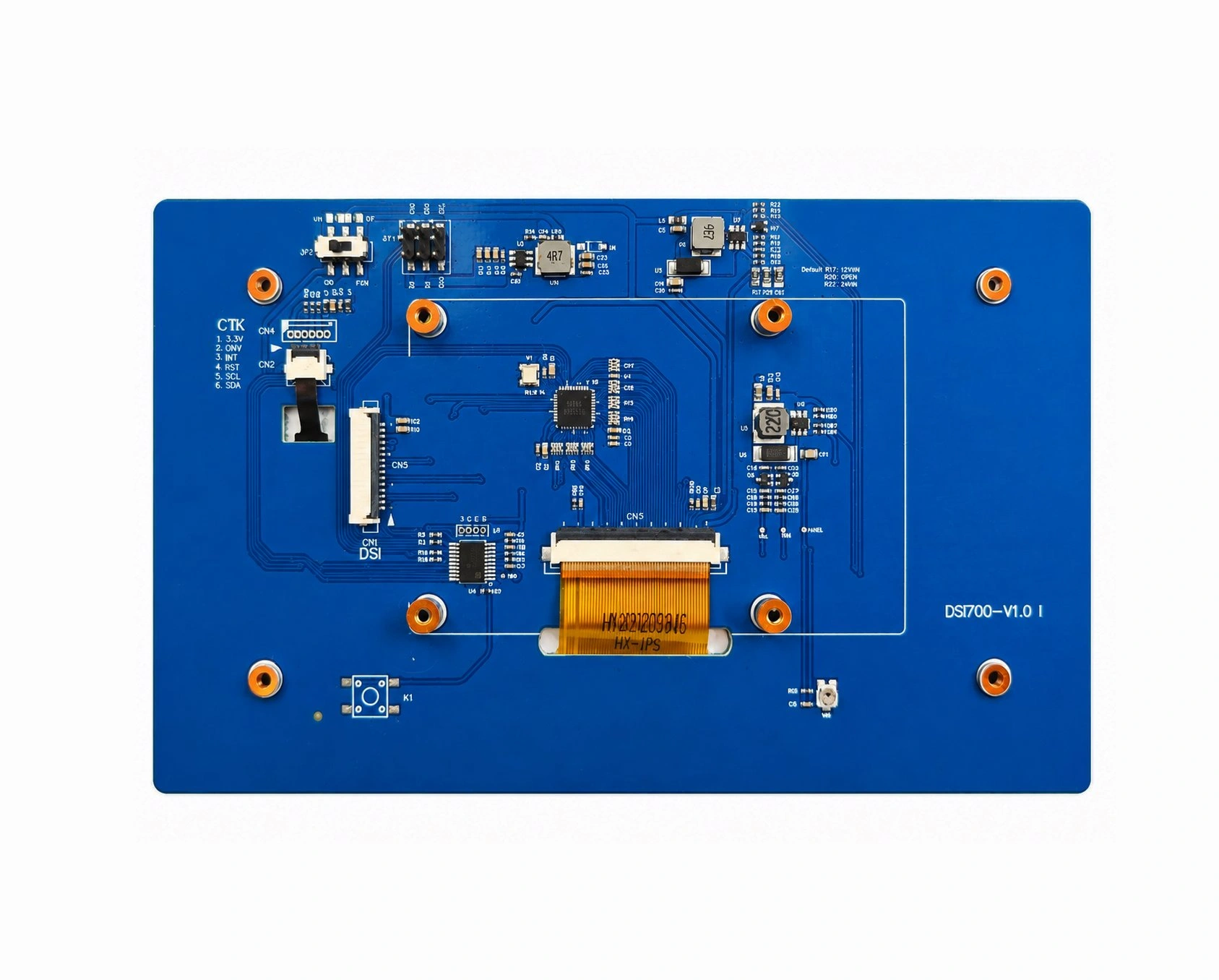
A listed 7-inch MIPI DSI touchscreen for Raspberry Pi provides a concrete example of a platform-oriented module with a 1024 × 600 display interface and I²C touch control. Compatibility with a different processor or custom board would still require a separate review.
Are the Power Rails, Reset, and Backlight Sequence Compatible?
A display may have the correct MIPI DSI signal configuration but still fail to start if its power requirements are not met.
Check:
- Panel logic voltage
- I/O voltage
- Backlight voltage and current
- Reset voltage level
- Enable or standby signals
- Required power-on sequence
- Reset timing
- Delay before initialization commands
- Sleep-out and display-on sequence
- Backlight enable timing
The processor board must provide the necessary rails directly or through an appropriate power circuit. It must also provide sufficient GPIO control for reset, enable, and backlight functions where required.
Do not use assumed universal delays. Reset and startup timing should be taken from the display, panel, or driver IC documentation.
Specifications 8–10: Verify Initialization, Operating-System Support, and Touch
Are the Driver IC Information and Initialization Commands Available?
Many MIPI DSI panels require an initialization sequence before they display an image. Procurement teams should confirm that the necessary technical files are available before ordering.
Useful materials include:
- Display driver IC model
- Initialization command sequence
- Display timing table
- Reset sequence
- DSI operating-mode requirements
- Reference source code
- Register settings
- Known platform configurations
Even a video-mode panel may require commands to exit sleep mode, select a pixel format, configure orientation, or enable display output.
If the supplier cannot provide enough information to initialize the panel, the hardware may appear compatible while the software integration remains impractical.
Does the OS or BSP Include Panel and Device Tree Support?
On embedded Linux, support for the processor’s DSI host controller is not the same as support for the selected panel.
The software stack may require:
- A DSI host-controller driver
- A DRM panel driver
- Display timing definitions
- Lane and format configuration
- Reset and enable GPIO definitions
- Power-supply definitions
- Backlight configuration
- Device Tree entries
- Panel-specific initialization commands
The Linux DRM subsystem treats display panels as defined components that can require panel-specific driver operations and integration with the surrounding display pipeline.
Before ordering, determine whether the panel is already supported, can use an existing compatible driver, requires a driver modification, or needs new driver development. The last option can materially affect project scope even when the electrical interface matches.
Is the Touch Controller Compatible with the Host?
Display compatibility and touch compatibility are separate checks.
The MIPI DSI link normally carries display data, while the touch controller may communicate through:
- I²C
- USB
- SPI
Confirm:
- Touch controller model
- Communication interface
- Required supply voltage
- I²C address, where applicable
- Reset and interrupt pins
- Operating-system driver availability
- Multi-touch support
- Coordinate rotation and mapping
- Whether touch signals share the display FPC or use a separate cable
A display can show an image correctly while its touch function remains unavailable because the host lacks the correct connection or driver.
How to Classify the Result: Direct, Conditional, or Not Directly Compatible
After completing the ten checks, classify the proposed combination before ordering.
|
Compatibility result |
Typical conditions |
Recommended action |
|
Directly compatible |
Host, lanes, bandwidth, timing, pinout, power, initialization, software, and touch requirements are already matched |
Order a sample and proceed to system-level validation |
|
Conditionally compatible |
The core DSI link is compatible, but the project needs an FPC change, adapter, Device Tree update, initialization work, or touch-driver modification |
Define the required modifications before ordering |
|
Not directly compatible |
No usable DSI host, incompatible PHY, insufficient bandwidth, unsupported timing, or unavailable software support |
Select another panel or evaluate a controller, bridge, or modular display architecture |
A datasheet match is not the same as complete-system validation. After receiving a sample, verify cold boot, restart behavior, display stability, touch response, backlight control, suspend and resume, enclosure clearance, FPC routing, cable access, and system power margin.
Should You Choose a Standard Module, Modified Module, or Modular Solution?
A standard module is the practical choice when the host interface, timing, software, connector, brightness, touch function, and mechanical layout already meet the project requirements.
For platform-based development, the Raspberry Pi display module range provides a starting point for applications using specified Raspberry Pi configurations. It can reduce interface uncertainty during prototyping when the selected product explicitly supports the intended board.
A modified module or custom display assembly may be more appropriate when the MIPI DSI signal is compatible but the project requires a different FPC, pinout, connector position, brightness, touch panel, cover glass, bonding method, or mechanical format. Kadi’s customized display solutions describe options involving brightness, thickness, interfaces, controller-board compatibility, and enclosure requirements.
When the host cannot drive the panel directly, a controller or modular solution may be more practical than redesigning the mainboard around a native DSI connection. The correct architecture depends on the available host output, software environment, installation space, and required level of integration.
This progression—from touch display module to custom display assembly and modular solution—is part of evaluating the complete device rather than treating the panel as an isolated component. More product and integration routes are available through industrial display and integration solutions from Kadi Display.
Information to Prepare Before Ordering a MIPI DSI Display
A useful compatibility request should include:
- Processor or SoC part number
- Development board or mainboard model
- Operating system and kernel version
- Available MIPI DSI lane count
- Maximum supported lane rate
- Required display size and resolution
- Target refresh rate
- Connector specification and pinout
- FPC length and exit direction
- Panel and I/O voltage
- Touch-Schnittstelle
- Brightness requirement
- Cover-glass or bonding requirement
- Application environment
- Mechanical drawing, when available
- Project stage and expected quantity
Providing these details makes it easier to determine whether the project should begin with a standard module, a modified product, a custom display assembly, or a controller-based solution. Project teams can submit the relevant specifications through contact Kadi Display about a MIPI DSI project without assuming compatibility from the interface name alone.
Schlussfolgerung
MIPI DSI display compatibility depends on much more than the connector label. Before ordering, match the host controller, PHY, lane count, bandwidth, timing, operating mode, pixel format, pinout, power sequence, initialization files, software support, and touch interface.
The result should be classified as directly compatible, compatible with defined modifications, or not directly compatible. Completing this review before sample purchase helps reduce unsuitable components, repeated PCB changes, and avoidable software integration work.
Häufig gestellte Fragen
Will Any MIPI DSI Display Work with Any MIPI DSI Processor?
No. The host and display must also match in PHY type, lane count, lane rate, display timing, operating mode, pixel format, pinout, power sequence, initialization requirements, and software support.
Is the Same MIPI DSI Connector Enough to Confirm Compatibility?
No. Connectors with the same pin count may use different pitches, contact orientations, voltage rails, lane assignments, reset pins, and touch connections. Compare the complete pinout before connecting the display.
Does a MIPI DSI Display Need a Linux Driver?
The processor may already have a DSI host-controller driver, but the panel can still require a specific DRM panel driver, initialization sequence, timing definition, or Device Tree configuration.
Can I Use a MIPI DSI Display If My Board Only Has HDMI?
Not directly. The project would normally need a suitable HDMI-to-MIPI DSI controller or bridge, or a display designed for native HDMI input. Compatibility still depends on the panel, controller board, resolution, timing, and software configuration.
Should Touch Compatibility Be Checked Separately?
Yes. Touch commonly uses I²C, USB, or SPI rather than the MIPI DSI video link. The touch controller, wiring, voltage, interrupt signals, and operating-system driver must be checked independently.
Vorherige
How a Linux MIPI DSI Panel Driver Works on Raspberry Pi CM4: Timing, Initialization, Lanes, and Device Tree
Nächster
How to Calculate MIPI DSI Bandwidth and Data Rate per Lane for an Embedded Display
Hinterlasse einen Kommentar

Neueste Blog & Nachrichten
- Industrial LCD EOL: What Happens from Pre-Announcement to Replacement Mass Production?
- Electronic Component Obsolescence Management for Industrial Displays: An OEM Guide
- How to Develop a Production Ready Custom Display Assembly TFT Module Touch Cover Glass FPC Bonding and Mounting
- 15 Pin vs 22 Pin Raspberry Pi DSI Connectors Cable Pinout and Compatibility
- Native MIPI DSI vs LVDS or HDMI Bridge: An OEM Display Architecture Decision Guide

