Guía de selección de interfaz de visualización
2026-05-02
11:11
Guía de selección de interfaz de visualización
Pantalla MIPI · Pantalla RGB · Pantalla LVDS: Orígenes, especificaciones y cómo elegir
Por el equipo técnico de Kadi Display | www.kadidisplay.com Tecnología de pantallas industriales
Por qué la elección de la interfaz es la primera decisión, no una consideración posterior.
Todo proyecto de pantalla integrada se enfrenta tarde o temprano a la misma pregunta: ¿qué interfaz usar? Y es una pregunta más compleja de lo que parece, ya que la respuesta varía según el tamaño del panel, la plataforma del procesador, la longitud del cableado, el presupuesto de producción y el entorno de ruido en el que se ubicará el dispositivo. Si se comete un error desde el principio, se termina teniendo que rediseñar la placa de circuito impreso o comprometiendo la velocidad de fotogramas y la resolución de forma muy difícil de solucionar posteriormente.
Esta guía abarca las principales interfaces de visualización actuales: su origen, sus ventajas y cuándo elegir una u otra. Se hace hincapié en las aplicaciones industriales y embebidas: RGB paralelo, LVDS y MIPI DSI se tratan con mayor profundidad, ya que son las interfaces más comunes en prácticamente todos los proyectos HMI importantes. SPI, eDP, HDMI y VGA se abordan brevemente, dado que su alcance es demasiado limitado o específico para aplicaciones concretas como para justificar un tratamiento similar en el ámbito industrial.
Un mapa de todas las interfaces del mercado.
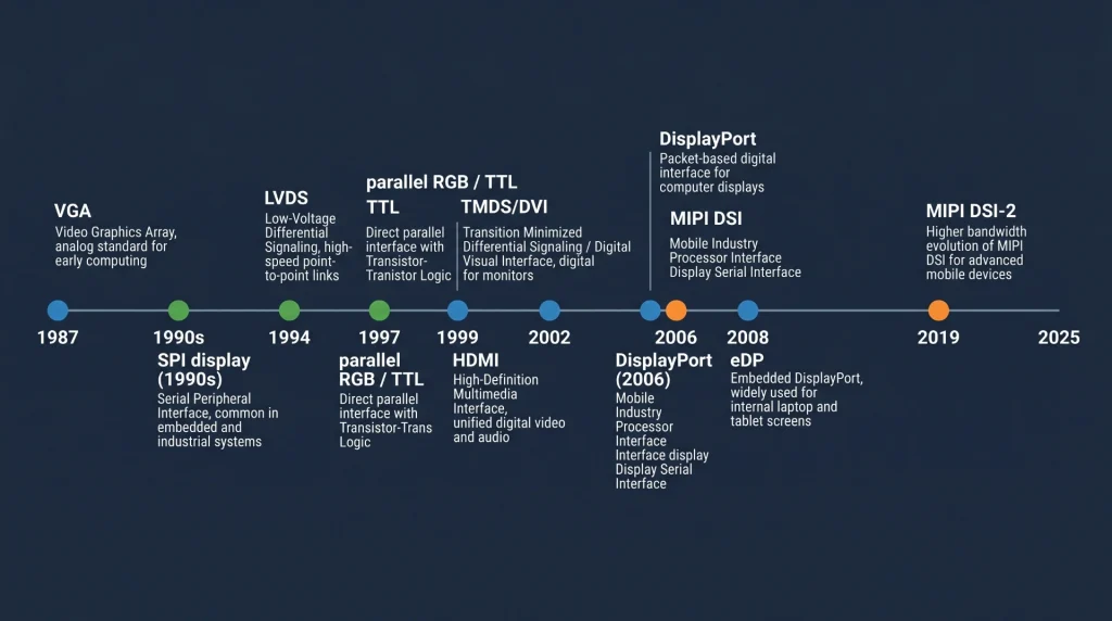
Antes de adentrarnos en las tres principales, conviene tener una referencia general que muestre la ubicación de cada una. La siguiente tabla resume las principales familias de interfaces de pantalla, la época a la que pertenecen y sus usos habituales en la actualidad.
Guía de referencia rápida de la interfaz de visualización
Hay algunos puntos que vale la pena destacar. VGA Se incluye porque aún se encuentra en proyectos de reemplazo de equipos industriales heredados: controladores CNC antiguos, terminales de planta de fábrica y dispositivos médicos de la década de 2000 que necesitan actualizaciones de pantalla. eDP Es el estándar en los módulos informáticos x86 modernos (Intel NUC, placas base Raspberry Pi CM4 y la mayoría de los PC de panel comerciales), pero rara vez se diseña desde cero en hardware integrado personalizado porque requiere chips controladores de temporización específicos. HDMI y DisplayPort Se trata principalmente de interfaces de consumo; aparecen en diseños integrados cuando la pantalla es un monitor comercial en lugar de un panel integrado.
Dato del sector: Según un análisis de mercado realizado por Display Supply Chain Research, los paneles con interfaz LVDS seguirán representando más del 35 % de los envíos mundiales de monitores industriales a partir de 2024, a pesar de ser una tecnología consolidada. La base instalada de hardware compatible con LVDS es demasiado grande como para que sea reemplazada rápidamente.
Interfaz de pantalla paralela RGB: la solución ideal para paneles industriales de tamaño mediano.
De dónde proviene
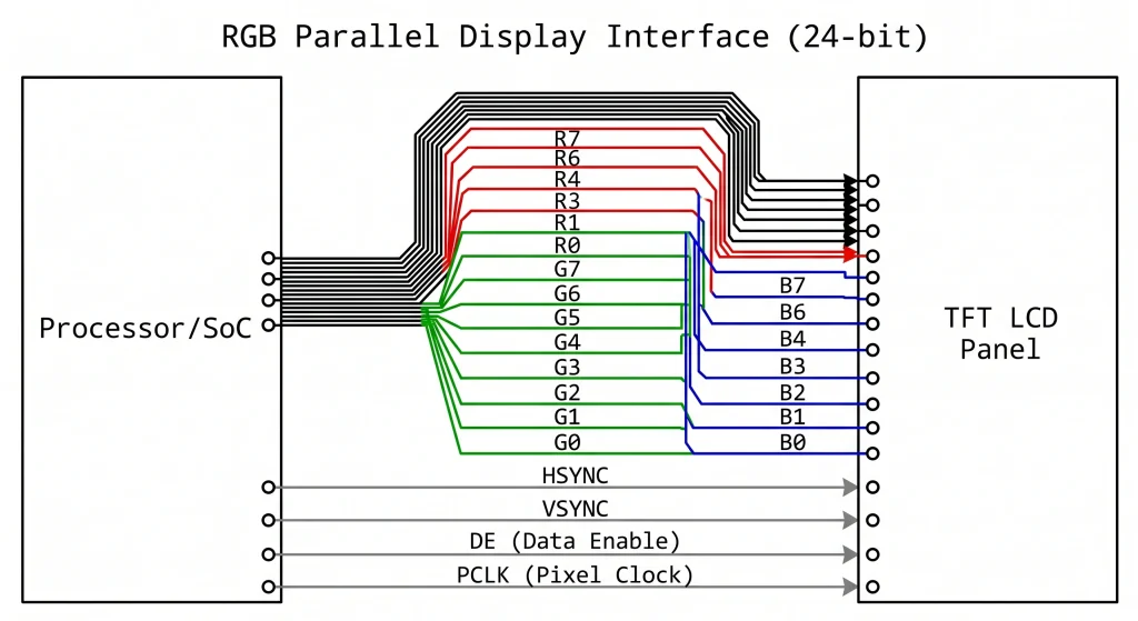
La interfaz RGB paralela —a veces llamada paralela TTL, DPI (Display Parallel Interface) o simplemente «LCD paralela»— surgió de una lógica simple: si se tienen suficientes pines GPIO y una lógica lo suficientemente rápida, se puede controlar un panel píxel a píxel, línea por línea, utilizando cables separados para cada bit de los canales rojo, verde y azul. La idea es tan antigua como el escaneo raster de los tubos de rayos catódicos (CRT). Lo que cambió a finales de la década de 1990 fue que los fabricantes de paneles LCD comenzaron a estandarizar una entrada paralela de 24 bits (8 bits para cada uno de los canales R, G y B) con HSYNC, VSYNC, DE (habilitación de datos) y un reloj de píxeles, lo que esencialmente consolidó un enfoque que todos podían utilizar.
Esto se convirtió en el RGB888 Interfaz que alimenta la mayoría de los módulos LCD TFT industriales en el rango de 4 a 12 pulgadas en la actualidad. Un panel de 7 pulgadas 800×480 a 60 Hz, por ejemplo, necesita un reloj de píxeles de alrededor de 33 MHz, lo que está cómodamente dentro de las capacidades de las etapas de salida GPIO de MCU/MPU de propósito general. En un STM32H7 o un NXP i.MX6El bloque de hardware del controlador de pantalla LCD-TFT (LTDC) gestiona automáticamente toda la sincronización: solo hay que configurar la resolución, el reloj y los parámetros de margen delantero/trasero, apuntar el LTDC a un búfer de fotogramas en la SDRAM, y el hardware transmite píxeles continuamente sin la intervención de la CPU.
Ancho de banda y límites prácticos
Las matemáticas son sencillas. Una pantalla de 800 × 480 a 60 fps con color de 24 bits y sincronización estándar requiere aproximadamente 27 MHz de reloj de píxeles. Un panel de 1024 × 600 a 60 fps requiere alrededor de 48 MHz. Un panel WXGA completo de 1280 × 800 a 60 fps alcanza aproximadamente los 71 MHz. Esto se puede lograr con un enrutamiento cuidadoso de la PCB, pero el bus paralelo empieza a generar problemas: 24 líneas de datos más 4 líneas de control son 28 pistas que necesitan un retardo de propagación similar para evitar artefactos en la imagen. Más allá de unos 10 cm de longitud de pista, es necesario considerar el enrutamiento de longitud coincidente, lo que aumenta la complejidad del diseño y el área de la PCB.
Más allá de 1280×800, la interfaz RGB paralela se vuelve impracticable. El reloj de píxeles supera los 80-100 MHz, y la conmutación simultánea de 24 líneas se convierte en una seria preocupación de EMI. Ese es el límite natural al que históricamente los ingenieros se han movido LVDSy más recientemente a MIPI DSI o eDP.
Donde RGB todavía tiene sentido
A pesar de sus limitaciones, el RGB paralelo seguirá presente en el mercado de pantallas industriales. El ecosistema de procesadores con LTDC o hardware equivalente es enorme: STM32 F4/H7, NXP i.MX6/7/8, Allwinner serie A, Rockchip RK35xx y TI AM335x/AM5xx admiten RGB paralelo de forma nativa. El precio de los paneles es competitivo. Y para pantallas de hasta 7-10 pulgadas a 60 fps, la interfaz es totalmente adecuada.
Productos recomendados: Módulos de pantallas LCD TFT industriales — Kadi Display — Una gama de paneles LCD TFT RGB y MIPI de 4,3 a 10,1 pulgadas con táctil capacitivo opcional, amplio rango de temperatura de funcionamiento y opciones de alto brillo de 400 a 1000 nits.
Interfaz de visualización LVDS: la opción fiable para grandes paneles industriales.
La ingeniería que hay detrás
Diferencial de baja tensión Señalización (LVDS) Se formalizó en la norma ANSI/TIA-644 en 1994, y la variante específica para pantallas —a veces llamada OpenLDI (Open LVDS Display Interface)— surgió de un esfuerzo de colaboración entre fabricantes de paneles a finales de la década de 1990. La idea principal es simple pero ingeniosa: en lugar de enviar un bit por cable a alto voltaje (como lo hace el RGB paralelo), LVDS envía cada bit como un par diferencial que funciona con una oscilación de voltaje mucho menor —típicamente 350 mV de pico diferencial, en comparación con 3,3 V para las señales TTL—.
Esa menor amplitud de oscilación hace que LVDS sea mucho menos susceptible al ruido y a las interferencias electromagnéticas, y también significa que el bus puede funcionar mucho más rápido por par: un solo carril LVDS puede transmitir datos serializados a velocidades de entre 100 Mbps y aproximadamente 1,5 Gbps, dependiendo de la implementación específica del silicio. Un enlace LVDS típico de un solo canal (1 par de reloj + 4 pares de datos = 10 cables en total) que funciona a 700 Mbps por par transmite el equivalente a un bus RGB de 24 bits que funciona a 65 MHz, lo que cubre fácilmente un panel de 1024 × 768 a 60 fps.
LVDS de un solo canal frente a LVDS de doble canal
Para paneles de hasta aproximadamente 1024×768 o 1280×800 a 60 fps, LVDS de un solo canal (4 pares de datos + 1 par de reloj) es suficiente. Para paneles más grandes — 1920×1080 Full HD a 60 fps, 1280×1024 SXGA a 75 Hz, o cualquier cosa que supere aproximadamente 110 MHz de reloj de píxeles equivalente — LVDS de doble canal Divide los datos en dos bancos de 4+1 pares, duplicando así el ancho de banda. El conector pasa de unos 20 pines a entre 30 y 40, pero las ventajas de integridad de la señal de LVDS sobre RGB paralelo se conservan por completo.
Un detalle práctico que suele sorprender a los ingenieros: LVDS utiliza un serializador en el procesador y un deserializador integrado en el controlador de temporización del panel. Esto significa que la señal LVDS en bruto no se genera directamente mediante el GPIO del procesador; se necesita un chip transmisor LVDS dedicado (como la familia SN65LVDS84 de Texas Instruments o equivalente) o un procesador con un bloque de salida LVDS integrado (presente en NXP i.MX6/8, Rockchip RK3399 y otros procesadores de aplicaciones). Considere el costo de la lista de materiales y el espacio en la placa de circuito impreso para dicho transmisor si su SoC no lo incluye.
Ventajas de la longitud del cable y la compatibilidad electromagnética (EMI)
Aquí es donde LVDS realmente destaca frente al paralelo RGB. Un enlace LVDS bien terminado puede funcionar de forma fiable a través de 50-100 cm de cable diferencial, a veces incluso más, dependiendo del controlador de temporización del panel y del silicio del transmisor. Por eso, casi todos los PC industriales, sistemas de visión embebidos y terminales de imágenes médicas utilizan LVDS para su enlace de visualización principal: el módulo de visualización se puede montar en la parte frontal de la carcasa, mientras que la placa de procesamiento se ubica en la parte posterior, con un cable de 30-50 cm entre ambos.
Nota práctica: Un error común en los diseños LVDS es usar una conexión a tierra de un solo extremo para el blindaje del cable en lugar de blindajes de pares diferenciales separados. En tendidos de cable largos en entornos industriales con interferencias eléctricas (accionamientos de motores, variadores de frecuencia, balastos de iluminación fluorescente), esto provoca fallos intermitentes en los píxeles, muy difíciles de reproducir en un laboratorio. Utilice cable de par trenzado blindado y asegúrese de que ambos extremos estén conectados a tierra en la carcasa del conector.
Explorar: Kadi Display — Gama de monitores y pantallas — Monitores industriales de 8 a 21 pulgadas con opciones de entrada LVDS, eDP y HDMI, funcionamiento en un amplio rango de temperaturas y niveles de brillo legibles a la luz del sol.
Interfaz de pantalla MIPI: nacida en dispositivos móviles, ahora avanza con fuerza en el sector industrial.
Orígenes y arquitectura
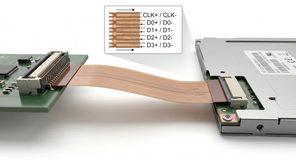
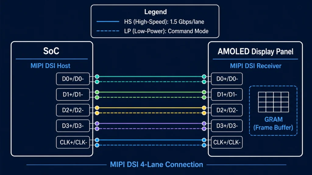
MIPI DSI (Interfaz serie de pantalla) Publicado por la Alianza MIPI en 2006, el estándar se centra principalmente en conectar pantallas de alta resolución a SoC de smartphones con un mínimo de pines y consumo de energía. La capa física (D-PHY) utiliza pares diferenciales con una amplitud de voltaje de 200 mV y admite velocidades de datos por carril desde 80 Mbps hasta 2,5 Gbps en la especificación D-PHY v2.1, y hasta 4,5 Gbps en modo C-PHY. Un enlace MIPI DSI de 4 carriles a 1,5 Gbps por carril proporciona un rendimiento bruto de 6 Gbps, suficiente para alimentar una pantalla AMOLED de 1080p a 90 Hz sin problemas.
El bus funciona en dos modos. El modo de alta velocidad (HS) se utiliza para la transmisión de datos de píxeles; el modo de baja potencia (LP) se utiliza para la transmisión de comandos durante la inicialización del panel y los cambios de modo de visualización. La capa de comandos DCS (Display Command Set) se sitúa por encima de las capas física y de protocolo, y proporciona una forma estandarizada de configurar el brillo, la rotación, el efecto de desgarro y otros parámetros del panel sin necesidad de conocer los detalles específicos del circuito integrado del panel, siempre que este sea compatible con DCS, como ocurre con la mayoría de los paneles MIPI modernos.
¿Por qué MIPI está ganando terreno en el sector industrial?
La respuesta se debe en parte a factores económicos y en parte a la disponibilidad de silicio. MIPI DSI es ahora la interfaz de visualización predeterminada en prácticamente todos los procesadores de aplicaciones modernos que utilizan Linux embebido: NXP i.MX 8M Plus, chip de roca RK3568/RK3588, Qualcomm SA8155, STM32H747/H7Bx, Raspberry Pi 4/5 — todos ellos incorporan controladores host MIPI DSI de serie. Los fabricantes de paneles han seguido la tendencia: la gama de paneles LCD y AMOLED MIPI DSI disponibles en tamaños de 4 a 10 pulgadas se ha ampliado drásticamente en los últimos cinco años, y los precios se han equiparado a los de los paneles RGB equivalentes.
La ventaja en el número de pines es decisiva para diseños compactos. Un enlace MIPI DSI de 2 carriles para un panel de 7 pulgadas y 1024 × 600 utiliza 6 pines de señal (1 par de reloj + 2 pares de datos + 1 reinicio + 1 VSYNC). El bus paralelo RGB equivalente necesita 28. Esta diferencia es crucial al diseñar una placa de circuito impreso de 4 capas para un dispositivo portátil con un formato limitado.
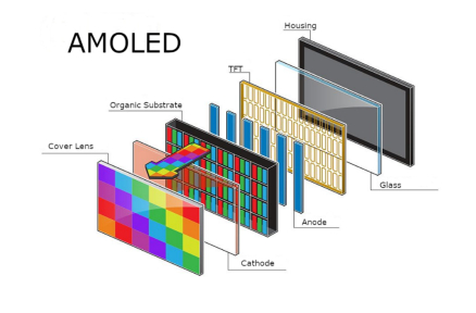
Los paneles AMOLED con MIPI DSI y GRAM (memoria gráfica) integrada ofrecen otra ventaja para las pantallas alimentadas por batería o con actualizaciones intermitentes: Modo de comando Funcionamiento. El panel mantiene su propio búfer de fotogramas, se actualiza de forma autónoma y solo necesita nuevos datos de píxeles cuando la imagen cambia. El SoC principal puede entrar en modo de suspensión entre actualizaciones. En un dispositivo de campo típico de IoT industrial que muestra lecturas de sensores que cambian cada pocos segundos, esto puede reducir el consumo de energía del subsistema de visualización entre un 60 % y un 80 % en comparación con un panel RGB en modo de vídeo que debe recibir datos de píxeles continuamente a 60 fps.
Explorar: Pantallas para Raspberry Pi — Kadi Display — Módulos de visualización MIPI DSI y HDMI verificados para Raspberry Pi 4 y Pi 5, con tamaños de 3,5 a 10,1 pulgadas y paneles táctiles opcionales.
Véase también: Módulos de pantalla AMOLED — Kadi Display — Paneles AMOLED compactos con interfaz MIPI DSI, adecuados para dispositivos vestibles, dispositivos portátiles industriales y equipos médicos portátiles.
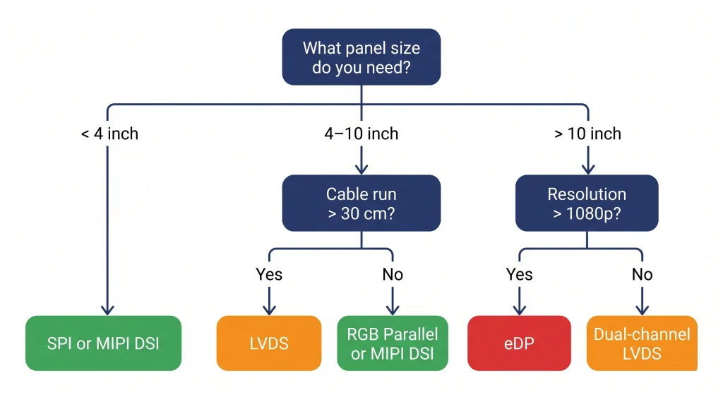
Guía práctica de selección: Cómo adaptar la interfaz a la aplicación
Las tres principales interfaces industriales —RGB, LVDS y MIPI DSI— se siguen integrando activamente en el diseño de nuevos productos. La elección depende de cinco factores: tamaño del panel, resolución objetivo, requisitos de cableado, compatibilidad con el procesador anfitrión y entorno operativo. La siguiente tabla relaciona los escenarios de proyecto más comunes con la interfaz adecuada.
Selección de interfaz según el escenario de aplicación
Algunos casos poco intuitivos que vale la pena conocer
¿LVDS para paneles de 7 pulgadas? Sí, a veces. Si la pantalla se encuentra a 30-50 cm de la placa de procesamiento en una carcasa de montaje en panel y el entorno de la fábrica tiene un ruido eléctrico significativo (accionamientos de motor, fuentes de alimentación conmutadas), la inmunidad al ruido superior de LVDS® hace que valga la pena el chip serializador adicional, incluso en un tamaño donde técnicamente funcionaría RGB.
¿MIPI para uso industrial? Cada vez más, sí, especialmente en plataformas basadas en Cortex-A. Si su SoC ya cuenta con hardware MIPI DSI (la mayoría de los modernos lo tienen) y el panel se encuentra a menos de 20 cm de la placa, MIPI DSI suele ser la solución más limpia: menos pistas en el PCB, menor interferencia electromagnética y un catálogo cada vez mayor de paneles compatibles.
¿RGB para nuevos diseños? Resulta más difícil recomendarlo como primera opción para diseños que se inicien hoy en día si el procesador es compatible con MIPI DSI. Sin embargo, RGB sigue siendo la solución adecuada cuando se necesita un panel específico que solo está disponible en RGB, o cuando el equipo de ingeniería necesita una puesta en marcha rápida en una plataforma con soporte para controladores RGB maduros y sin hardware MIPI.
Las otras interfaces: notas breves
SPI y Paralelo (8080/6800)
SPI Sigue siendo la opción predeterminada para pantallas pequeñas de menos de 3,5 pulgadas en microcontroladores sin controladores de pantalla por hardware (ESP32, Arduino, STM32G0/L4). Circuitos integrados de panel comunes: ILI9341, ST7789, GC9A01. El ancho de banda es limitado: con SPI de 40 MHz se obtienen entre 10 y 15 fps en una pantalla de 320 × 240 con color de 16 bits. Para cualquier aplicación que requiera una animación fluida en pantallas de más de 3 pulgadas, SPI resulta insuficiente. 8080 paralelo (8 o 16 bits) es el siguiente nivel, utilizado en ESP32-S3 y microcontroladores similares para paneles de hasta 800×480.
eDP (DisplayPort integrado)
eDP es ahora la interfaz dominante para paneles de portátiles y PCs con panel integrado x86. Si diseña un sistema basado en un módulo Intel NUC, NVIDIA Jetson o una plataforma x86/compatible similar, es probable que eDP sea su interfaz de visualización, ya sea que la haya elegido explícitamente o no; es la que produce la salida de pantalla del módulo. El ancho de banda es excelente (hasta 8,1 Gbps por carril en eDP 1.4b, con 4 carriles disponibles), y el número de carriles se adapta perfectamente desde 1 carril para paneles pequeños hasta 4 carriles para pantallas 4K.
HDMI y DisplayPort
Se trata de interfaces AV para uso doméstico y profesional, incluidas aquí a modo de información completa. En diseños industriales integrados, aparecen cuando la pantalla es un monitor HDMI estándar en lugar de un panel integrado; por ejemplo, en los monitores de las estaciones de trabajo de los operarios en las fábricas o en la señalización digital de gran formato controlada por un PC integrado. Normalmente no se utilizan para la conexión directa al panel en hardware personalizado debido a la complejidad eléctrica (TMDS/HDCP para HDMI, canal AUX para DP) y al hecho de que los paneles integrados no exponen las entradas HDMI/DP a nivel de panel.
VGA
Analógico, obsoleto y en vías de desaparecer. Merece la pena mencionarlo porque un número considerable de proyectos de mantenimiento industrial aún implican la sustitución o ampliación de pantallas en equipos de la década de 2000 con salida VGA. En ese caso, una placa convertidora de VGA a HDMI suele ser la solución más sencilla que rediseñar la interfaz de la pantalla.
Resumen: ¿Con qué interfaz debería empezar?
Aquí tienes la versión corta y honesta. Si estás diseñando un producto industrial desde cero con un procesador de aplicaciones moderno y una pantalla de entre 5 y 10 pulgadas, primero verifica si tu SoC cuenta con hardware MIPI DSI. Si lo tiene, y el panel que has elegido dispone de una versión MIPI DSI, probablemente sea la opción más sencilla. Si la pantalla es grande (10 pulgadas o más) o necesita estar a más de 20-30 cm de la placa, LVDS es la solución ideal. El paralelismo RGB es una alternativa sólida cuando tu procesador cuenta con hardware LTDC o equivalente y el panel funciona a 800×480 o 1024×600.
Y si aún te encuentras en las primeras etapas de la selección de componentes, antes de haberte decidido por un procesador o un panel, elegir la interfaz y luego encontrar el silicio que la soporte de forma nativa te ahorrará más tiempo de ingeniería que casi cualquier otra decisión inicial.
¿Busca paneles que abarquen todos estos tipos de interfaz? Explore el catálogo completo de productos de Kadi Display. — Cubrimos módulos de visualización TFT LCD, AMOLED, de alto brillo, tipo barra y personalizados con interfaces RGB, LVDS, MIPI DSI y SPI en tamaños de 1,3 a 21 pulgadas. Personalización OEM y ODM disponible con plazos de entrega reducidos desde Shenzhen.
¿Necesita un adaptador de interfaz personalizado o un tamaño de panel específico que no aparece en la lista? El equipo de ingeniería de Kadi Display se encarga de proyectos ODM, incluyendo diseños de conectores FPC personalizados, integración de circuitos integrados de puente de interfaz y cualificación de paneles para un amplio rango de temperatura. Contacto: Sales@sz-kadi.com
Descargo de responsabilidad: Todas las especificaciones de interfaz mencionadas en este artículo provienen de documentos de estándares públicos (ANSI/TIA-644, especificaciones públicas de MIPI Alliance, JEDEC y hojas de datos de los fabricantes). Las marcas comerciales pertenecen a sus respectivos propietarios. Las cifras de ancho de banda son máximos teóricos; el rendimiento real depende de la implementación. Este artículo no constituye un respaldo a ningún producto en particular.
PREVIOR
Tratamiento antirreflejos y antideslumbrante para pantallas industriales
Siguiente
Interfaz de visualización MIPI
Deja un comentario

Últimos blogs y noticias
- LCD Ribbon Cable Connector Guide: How to Specify ZIF, FFC/FPC, Pitch, and Contact Direction
- MIPI DSI Display Bring-Up Checklist: Eight Evidence Gates
- MIPI DSI LCD Platform Selection Guide: Match the Panel to the Host
- Common ZIF Connector Problems in Industrial Touchscreens and How to Fix Them
- ESP32-S3 RGB Display with GT911 and LVGL: A Practical Guide for Kiosk and HMI Applications