BLOG Y NOTICIAS
Inicio
-
Blog & Noticias
-
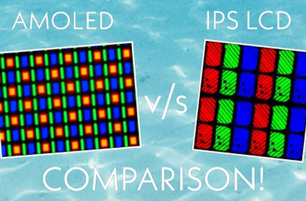
Zero Insertion Force Connectors in Industrial LCD Displays: Why They Matter

A practical overview of ZIF connector roles in LCD modules, touch panels, and backlight FFC/FPC assemblies
Por el equipo técnico de Kadi Display | www.kadidisplay.com
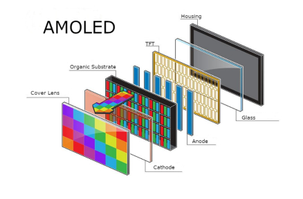
In an industrial LCD display, the most visible parts are the cover glass, the TFT panel, the touchscreen, and the metal housing. The ZIF connector is easy to overlook because it is small, inexpensive, and often hidden on the rear PCB. Yet many display failures begin exactly there: a half-inserted FPC, a broken latch, the wrong contact direction, or a flex cable that bends too sharply at the connector exit.
A zero insertion force connector, usually shortened to ZIF connector, is designed so a flexible flat cable or flexible printed circuit can be inserted with very low force before it is locked in place by an actuator. Molex describes ZIF as a mechanism in which a zero-insertion-force actuator allows no-friction mating and supports a higher mating lifecycle. In LCD assemblies, that simple idea protects fragile flex cables and fine-pitch contacts from being damaged during assembly and service.
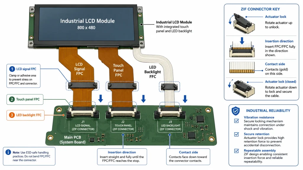
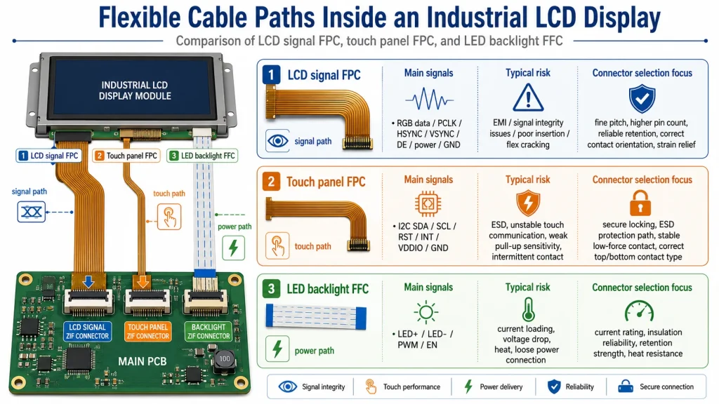
For industrial displays, ZIF connectors appear in three important places. The first is the LCD signal FPC, which carries display data such as RGB, LVDS, MIPI DSI, eDP, SPI, or MCU interface signals. The second is the touch panel FPC, which connects a PCAP or resistive touch sensor to a controller board. The third is the LED backlight cable, where the current level is often higher and the thermal design matters more. These three cable paths do different jobs, so they should not be specified with the same assumptions.
Kadi Display’s own engineering content mentions adapter boards with ZIF connectors for MIPI DSI Raspberry Pi display integration and also highlights FPC strain relief in 24/7 GT911 LVGL touchscreen projects. Those details are useful reminders: the connector is not a passive afterthought. It is part of the display system’s mechanical, electrical, and production reliability strategy.
The phrase zero insertion force does not mean zero mechanical pressure after assembly. It means the FPC or FFC can be inserted without forcing it against spring contacts. After insertion, the actuator closes and creates the contact pressure needed for electrical continuity and cable retention. This is different from non-ZIF or low-insertion-force connectors, where the cable may push directly against the contacts during insertion.
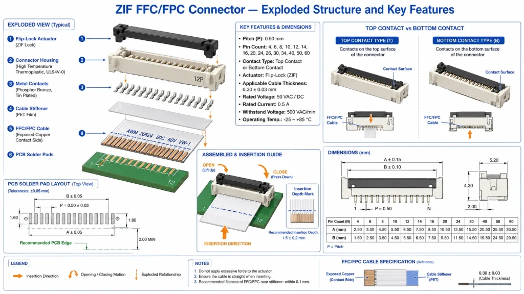
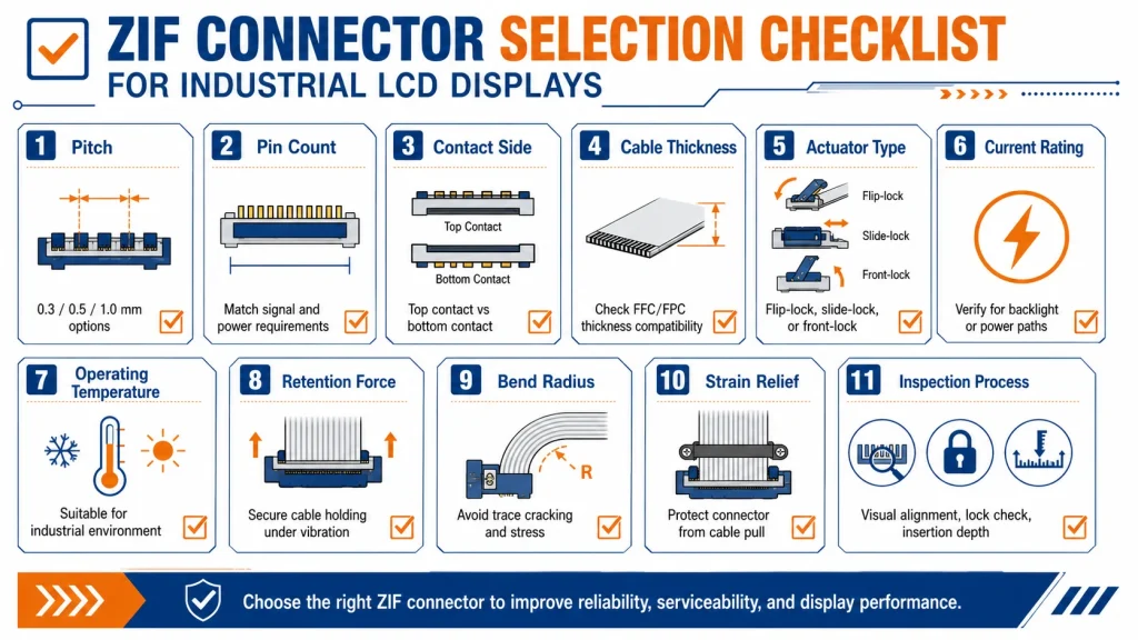
This distinction matters for fine-pitch display cables. Many LCD module flex cables use narrow pitch spacing, often around 0.5 mm or 1.0 mm in industrial display assemblies, and some compact products go smaller. TE Connectivity’s FPC connector portfolio, for example, lists centerline spacing options including 0.25 mm, 0.3 mm, 0.5 mm, 1.0 mm, and 1.25 mm, with ZIF and non-ZIF versions available. At this scale, an operator cannot rely on force and visual judgment alone.
A good ZIF connector controls the insertion geometry. The actuator, contact spring, housing, FPC stiffener, and PCB footprint work together. If the cable thickness is wrong, the contact pressure is wrong. If the exposed copper side faces the wrong way, the connector may close perfectly but carry no signal. If the actuator is blocked by the enclosure wall, maintenance becomes difficult and field repair can damage the part.
In consumer electronics, a connector may only be mated once during factory assembly. In industrial LCD displays, the connector may also be opened during incoming inspection, repair, firmware board replacement, touchscreen replacement, or cable rework. That is why connector durability, actuator robustness, and assembly process control deserve attention.
The LCD signal connector carries the image data and control signals. Depending on the module, the connector may route RGB, LVDS, MIPI DSI, eDP, SPI, parallel MCU, I2C, reset, enable, or power pins. Because the signal path can be high pin count and electrically sensitive, the connector pitch, contact resistance, PCB footprint, and FPC routing must match the panel drawing exactly.
For a simple SPI display, the connector may have relatively few pins. For a high-resolution industrial TFT LCD, the FPC may carry many differential pairs or a wide parallel bus. The connector is therefore part of signal integrity. A half-seated cable can show as white screen, colored lines, flicker, partial image, no image, or random startup behavior. These symptoms are often misdiagnosed as a driver IC or firmware problem.
The touch connector links the cover glass sensor or touch controller to the display electronics. In a PCAP design, the flex may carry I2C, interrupt, reset, power, ground, and sensor-related signals. In a resistive touch design, it may carry analog X/Y lines. The electrical speed is usually lower than LCD data, but touch signals are sensitive to ESD, grounding, moisture, and noise.
For industrial HMI panels, touch failures can look random: ghost touch, no touch, false double-click, coordinate drift, or touch not working after the unit warms up. The connector may not be the only cause, but it is one of the first places to inspect. Cable insertion depth, contact side, actuator closure, and mechanical strain relief should be part of every touch-panel failure checklist.
The LED backlight path is different because it may carry higher current. A display signal FPC is usually a signal connector. A backlight cable is a power path. In high-brightness industrial displays, the LED current can be significant, and the connector must be checked for current rating, temperature rise, conductor width, and mechanical retention.
If the backlight connector is under-rated, the display may show intermittent dimming, local heat, dark screen failures, or unstable brightness after vibration. For 1000-nit and 2000-nit industrial LCD displays, backlight interconnect design should be reviewed as carefully as the LED driver and thermal path.
Connector datasheets often reveal why general assumptions are risky. A Hirose FH52 series datasheet lists 0.5 mm and 1.0 mm pitch ZIF connectors with a rated current of 0.5 A, rated voltage of 50 V AC rms, and an operating temperature range of -40°C to +105°C for the referenced series. Those figures are useful, but they are not universal. Another connector family may have different ratings, fewer mating cycles, or a different acceptable cable thickness.
Molex states that its Easy-On FFC/FPC connector portfolio spans pitch sizes from 0.20 to 2.00 mm and circuit sizes from 2 to 96, with actuator styles including front flip, back flip, slider, one-touch, and LIF. That variety is helpful, but it also means there is no single generic ZIF connector that fits every industrial LCD display. The display drawing, connector drawing, and assembly process must be aligned before the PCB is released.
In a desk prototype, the display may sit flat, the cable is rarely moved, and the enclosure is open. In a factory HMI, the display is mounted vertically, connected through a cabinet, exposed to vibration, and sometimes serviced by technicians who did not design the product. Thermal cycling also expands and contracts the FPC, connector housing, PCB, and enclosure at different rates.
This is why industrial display suppliers pay attention to cable routing and strain relief. Kadi Display’s GT911 LVGL touchscreen stability guide specifically recommends applying a low-durometer silicone strain relief bead where the FPC exits the ZIF connector body, then inspecting the joint during incoming quality control. That kind of practical process step is often more important than choosing a more expensive connector series.
A connector with excellent electrical ratings can still fail if the FPC is bent sharply at the latch, pulled sideways by a housing wall, or routed across a hot backlight driver. A low-cost connector can perform reliably if the pitch, cable thickness, contact side, retention, strain relief, and assembly method are controlled. Industrial reliability is usually a system result, not a single part number result.
Many display problems are investigated in software first because the symptom appears on the screen. But an LCD driver cannot fix a cable that is half inserted. LVGL cannot solve a touch FPC that is twisted or unsupported. A backlight PWM setting cannot compensate for a connector contact heating under continuous current. The troubleshooting sequence should therefore include a connector check before deep firmware debugging.
A practical production rule is to mark the FPC with an insertion-depth line. After assembly, the line should sit parallel to the connector edge. If the line is angled, the cable is skewed. If the line is too far out, the cable is not fully inserted. This simple visual control can prevent a surprising number of field failures.
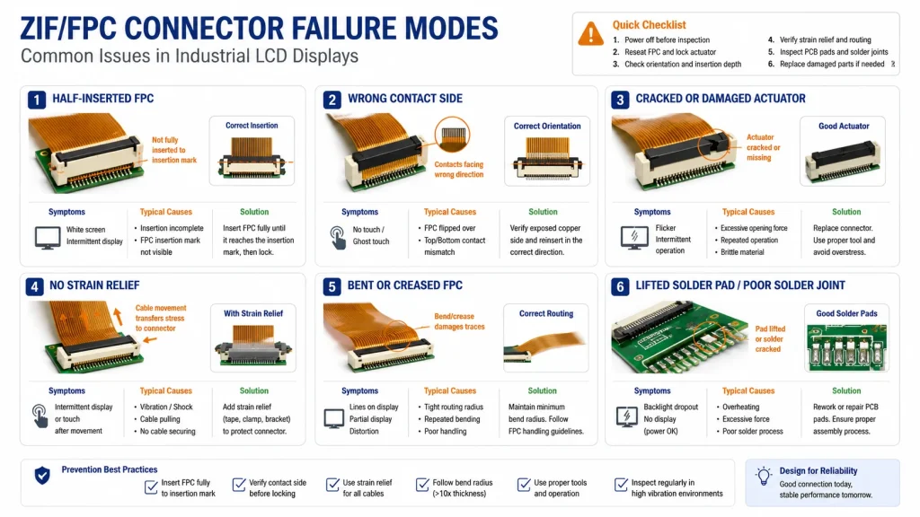
ZIF connectors are designed to reduce insertion force, but they still require correct handling. Operators should open the actuator fully, align the FPC straight, insert to the specified depth, close the actuator evenly, and avoid pulling the cable upward while locking. The connector should not be used as a cable clamp; it is an electrical interface with limited mechanical strength.
Hirose’s FH52 documentation warns against excessive rubbing of the FPC or FFC against the connector opening because it can deform contacts or peel conductive traces. That warning is very relevant to LCD production, where operators may insert thousands of fine-pitch flex cables per shift. The best prevention is not only training but also fixture design: a simple alignment guide can reduce skew and damage.
For industrial LCD display production, incoming quality control should include connector body inspection, latch movement check, FPC stiffener thickness confirmation, insertion-depth verification, and a functional test after thermal stabilization. For high-value HMI modules, a brief vibration or flex check may reveal marginal assemblies before shipment.
ZIF is not always the best answer, but it is often the most practical one for LCD module assembly. It balances thin form factor, repairability, manageable cost, and easy cable replacement. For a touch panel that may be replaced during service, ZIF is usually better than soldering. For high-current LED backlight paths, a dedicated wire-to-board connector may be more robust than forcing too much current through a fine-pitch FFC.
The correct choice depends on the module architecture. A small 3.5-inch SPI LCD may use a simple FPC ZIF connector. A 10.1-inch industrial TFT with PCAP touch may use separate LCD and touch FPCs. A 2000-nit high-brightness display may use a separate backlight harness because the current and heat are too high for a small signal connector.
Before releasing an LCD controller board, engineers should review the connector from both the electrical and mechanical sides. The following checklist is deliberately practical: it is the kind of list that prevents late-stage re-spins and production rejects.
If you are buying an industrial LCD display module, ask for more than the display resolution and brightness. Request the connector drawing, FPC pinout, recommended mating connector, cable thickness, contact side, backlight current, and any assembly notes. If the display uses a touch panel, ask whether the touch FPC and LCD FPC are independent and whether the touch controller is on the display module or the customer PCB.
For OEM projects, do not approve a display sample until the final enclosure, cable routing, and mounting method are reviewed. A display that works on the bench may fail when the cable bends in the real housing. If the product will face vibration, thermal cycling, or field service, ask the supplier about strain relief, connector locking style, and replacement procedure.
For Kadi Display internal links, ZIF connector content can naturally connect to MIPI DSI Raspberry Pi display integration, industrial TFT touch display modules, GT911 touchscreen reliability, custom cover glass, optical bonding, and embedded HMI display articles. The best anchor text is not generic “click here” language, but specific phrases such as Módulos de pantalla táctil TFT-LCD industriales, MIPI DSI adapter boards, and GT911 LVGL touchscreen stability.
Zero insertion force connectors matter because industrial displays depend on flexible interconnects. The LCD panel, touch sensor, and backlight are often connected through FPC or FFC cables, and each cable path has different electrical and mechanical requirements. The connector must match the pitch, pin count, contact side, cable thickness, current rating, operating temperature, actuator access, and service expectation.
A ZIF connector is not automatically reliable because it is called ZIF. It becomes reliable when the connector series, FPC design, PCB footprint, enclosure clearance, cable bend radius, strain relief, and production inspection all agree with one another. For industrial LCD displays, that agreement is what turns a fragile flex cable into a stable field-ready interconnect.
Engineers who treat ZIF connectors as part of the display architecture, rather than a small purchasing detail, will avoid many common failures: white screens, flicker, intermittent touch, backlight dropout, and post-service defects. In rugged HMI design, the reliability of the screen often begins with a connector that most users never see.
Molex FFC/FPC Connectors – Used for ZIF definition, actuator types, pitch/circuit range, and assembly-related connector features.
TE Connectivity Standard FPC Connectors Quick Reference Guide – Used for FPC connector centerline spacing, ZIF/non-ZIF availability, top/bottom contact options, and no-tooling features.
Hirose FH52 Series Datasheet – Used for example values such as 0.5/1.0 mm pitch, 0.5 A rating, 50 V AC rms rating, -40°C to +105°C operating range, and assembly precautions.
Kadi Display MIPI DSI Raspberry Pi Guide – Used for Kadi internal link context where adapter boards include ZIF connectors to mate display FPCs.
Kadi Display GT911 LVGL Touchscreen Stability Guide – Used for FPC strain relief and industrial touchscreen stability context.