




MIPI DSI in Industrial LCD Displays: What Engineers Should Know
2026-09-13
08:50
MIPI DSI in Industrial LCD Displays: What Engineers Should Know
Introducción
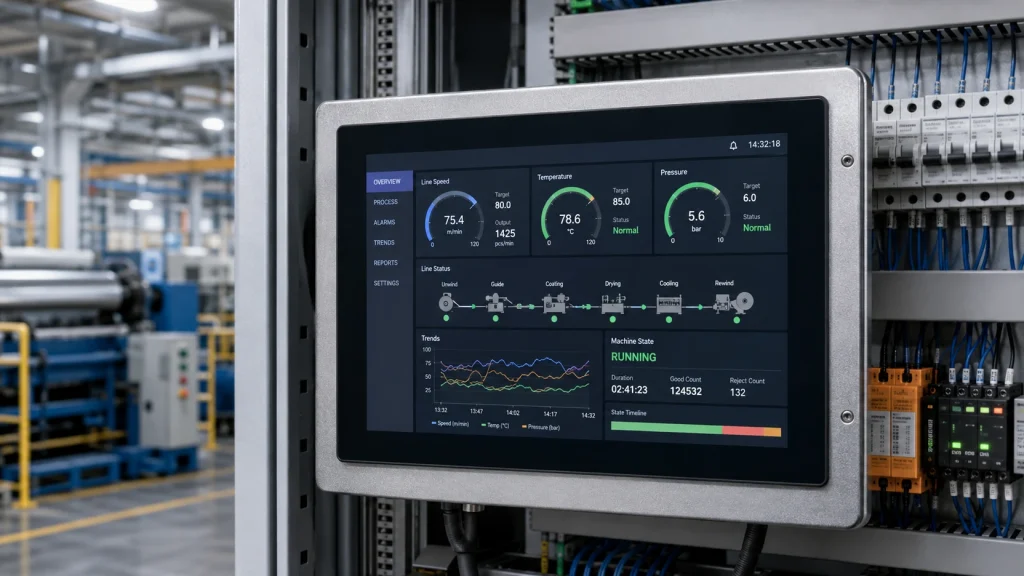
Walk into any modern factory automation bay, medical diagnostic suite, or self-service kiosk installation, and you will find TFT LCD panels quietly running process visualizations, patient-monitoring interfaces, and checkout UIs. Behind most of those screens — especially in products designed after 2015 — sits a single display interface: MIPI DSI.
MIPI DSI (Display Serial Interface) is a high-speed serial protocol developed by the MIPI Alliance that has become the de facto standard for connecting application processors to LCD panels in embedded and industrial systems. Yet despite its ubiquity, many engineers encounter MIPI DSI for the first time only when they open a SoC datasheet and find it is the only display output available. This article is a practical overview: what MIPI DSI actually is, why it suits industrial LCD applications, where it has real limitations, and how to make sound design decisions around it.
What Is MIPI DSI? A Quick Technical Foundation
The MIPI Alliance published the first Display Serial Interface (DSI) specification in 2006. The goal was to replace the proliferating tangle of proprietary parallel display buses on mobile SoCs with a single, royalty-accessible standard. Version 1.3 is still the most widely deployed in industrial hardware; DSI-2 (which adds C-PHY and higher lane rates) is gaining ground in new silicon launched after 2022.
At the physical layer, MIPI DSI uses D-PHY — a source-synchronous differential signaling standard operating at a nominal 200 mV differential swing. A link consists of one clock lane (CLK+ / CLK−) and one to four data lanes (D0 through D3, each a differential pair). Each D-PHY lane supports up to 4.5 Gbps in the high-speed (HS) state. In low-power (LP) mode, the same lanes drop to single-ended 1.2 V signaling for control traffic and ULPS (ultra-low-power state), where lane current falls to roughly 1 µA.
The protocol layer sits above D-PHY and defines two fundamental packet types: short packets (4 bytes, used for register writes and commands) and long packets (variable payload, used for pixel data and extended commands). Display Command Set (DCS) commands — a standardized vocabulary of read/write operations — allow the host processor to initialize the panel, adjust brightness and gamma, and control power sequencing without knowing the panel’s internal register map in detail.
Table 1 — MIPI DSI At a Glance
For a worked example of how these parameters translate into pixel clock requirements, see Kadi Display’s detailed article How to Read a MIPI DSI Timing Table: Pixel Clock, Porches, Sync Width, and Refresh Rate.
Video Mode vs Command Mode: The Distinction That Matters Most for Industrial Design
The single most important MIPI DSI concept for industrial LCD display engineers is the distinction between video mode and command mode. Many engineers who have worked with RGB parallel interfaces encounter it for the first time when qualifying a new panel and find the two modes behave very differently in practice.
Modo de vídeo
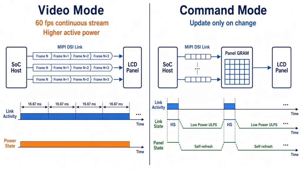
In video mode, the host SoC continuously streams pixel data to the panel at a fixed refresh rate — typically 60 Hz. The panel has no internal frame buffer (GRAM); it relies entirely on the host to push every frame. This is operationally identical to an RGB parallel interface in terms of the host-side rendering pipeline, and it is the mode most TFT LCD panels default to in their initialization sequences. It is also the mode that display drivers on Linux (DRM/KMS) and Android (SurfaceFlinger) assume unless explicitly configured otherwise.
Modo de comando
In command mode, the panel contains internal GRAM (Graphics RAM). The host pushes pixel data only when the content changes; the panel refreshes its own display from GRAM at the native panel rate. Between updates, the DSI lanes can enter ULPS, dropping interface power to near zero. For an industrial LCD display showing a relatively static HMI screen — process status, alarm states, temperature readings — command mode can reduce interface power by 40–70% compared to continuous video-mode streaming at 60 fps.
The trade-off: command mode panels are less common, cost 10–20% more than equivalent video-mode panels, and require additional host-side software to manage partial update regions (dirty rectangles). Tearing may also require synchronization via TE (tearing effect) signaling.
Table 2 — Video Mode vs Command Mode
If you are evaluating whether your host SoC and panel combination can actually support command mode, Kadi Display’s practical checklist — Can Your Host and Panel Support MIPI DSI Command Mode? An Embedded HMI Selection Checklist — walks through the host controller register checks and panel GRAM verification steps required before committing to this approach.
Why MIPI DSI Is Well-Suited to Industrial LCD Displays
MIPI DSI was designed for mobile applications, but its characteristics align surprisingly well with industrial LCD display requirements. Here is why it has become dominant in embedded industrial designs.
Bandwidth That Scales with Resolution
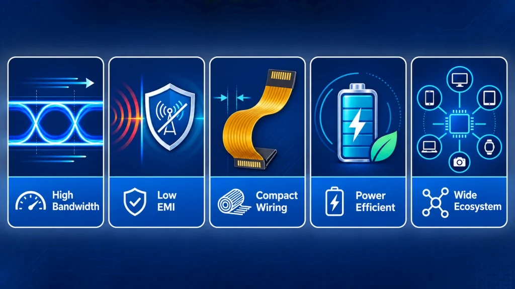
A single MIPI DSI lane at 4.5 Gbps (D-PHY) carries enough data for a 1080p panel at 60 fps with margin. A 4-lane link provides 18 Gbps aggregate — sufficient for 4K at 60 fps, or dual 1080p displays from a single DSI host using display split modes. For the 720p and 1080p resolutions that dominate 7″–15.6″ industrial LCD display applications, MIPI DSI provides comfortable headroom with a 2-lane or 4-lane configuration, leaving design margin for higher refresh rates or extended color depth without a hardware change.
EMI Compliance in Noise-Sensitive Environments
Industrial environments — manufacturing lines, medical equipment bays, outdoor enclosures — impose strict EMI requirements. EN 55032 Class B, FCC Part 15 Subpart B, and IEC 61000-4-3 (radiated immunity) all present challenges for display interfaces. MIPI DSI’s differential D-PHY signaling, with its ±100 mV common-mode rejection and sub-200 mV differential swing, produces radiated emissions roughly two to three orders of magnitude lower than a 24-bit RGB parallel bus switching at 33 MHz. In practical EMC pre-compliance testing, replacing an RGB interface with MIPI DSI on the same PCB has been shown to reduce radiated emissions in the 100–300 MHz band by 8–15 dBµV/m — often the difference between passing and failing EN 55032 without additional shielding measures.
Compact Wiring and Single-FPC Integration
A 4-lane MIPI DSI link requires just 10 signal lines (4 lane pairs + clock pair) plus power and ground — typically 15–24 pins total on an FPC connector. Compare this to 30+ lines for an 18-bit RGB interface. The reduced pin count means narrower FPC ribbons (as narrow as 10 mm for a 2-lane link), fewer routing constraints on the PCB, and a single FPC that often also carries the I2C bus for the capacitive touch controller and the backlight PWM signal. This single-FPC architecture reduces connector count on both the host PCB and the display module, directly lowering assembly cost and improving mechanical reliability in high-vibration environments.
Power Efficiency
In ULPS, all D-PHY lanes draw approximately 1 µA combined. Even in active high-speed mode, the sub-200 mV differential swing means the interface dissipates 15–40 mW (PHY transmitter + receiver), compared to 60–150 mW for an RGB parallel bus switching 24 lines at 3.3 V CMOS levels at 33 MHz pixel clock. For industrial handhelds, portable diagnostic equipment, and battery-backed emergency control panels, this 3–5× reduction in interface power is significant over a product lifetime.
Broad SoC and Panel Ecosystem
Every major application processor platform used in industrial embedded designs — NXP i.MX 6/7/8/93, Rockchip RK3568/RK3588, Raspberry Pi CM4/CM5, MediaTek MT8395, Qualcomm QCS6490, Texas Instruments AM69 — includes a native MIPI DSI host controller. Panel availability spans 2″–21.5″ from AUO, Innolux, BOE, Sharp, Kyocera, and Tianma in resolutions from QVGA to 4K. This breadth gives industrial system designers flexibility to source display panels from multiple vendors without changing the host interface — a critical supply-chain resilience benefit for products with 5–10 year production lifetimes.
Real Limitations Engineers Must Plan Around
MIPI DSI is not without constraints. Understanding them before committing to a design saves costly surprises during bring-up.
Cable Length Is a Hard Physical Constraint
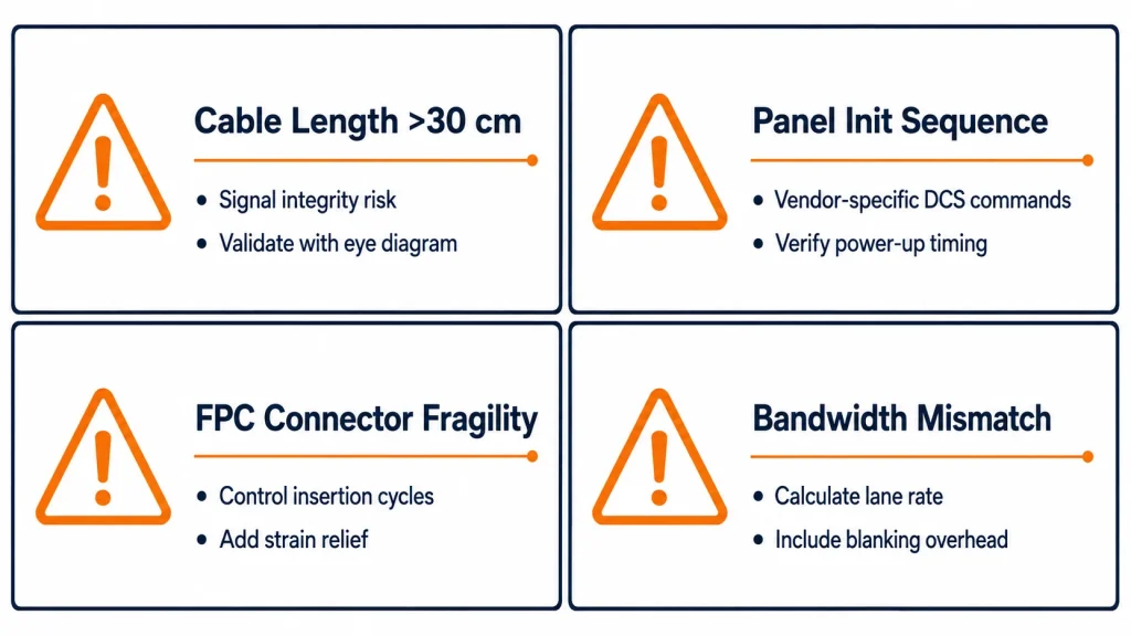
MIPI DSI FPC assemblies operate reliably up to approximately 30 cm. Beyond this, signal integrity degrades due to impedance discontinuities, inter-lane skew accumulation, and differential pair attenuation — all of which manifest as pixel artifacts, CRC errors in DSI long packets, or complete link failure. Designs that require more than 30 cm of separation between host board and display panel — common in panel PCs, split-architecture kiosks, and vehicular HMI — must use LVDS or add a MIPI DSI-to-LVDS bridge chip (e.g., Toshiba TC358775XBG, Lontium LT8912B). Bridge chips add $2–$6 USD to BOM and require separate power rails and initialization, but they are a well-proven solution.
Panel Initialization Complexity
Unlike RGB parallel, where the host can begin streaming pixel data immediately after power-up timing is met, MIPI DSI panels require an initialization sequence of DCS commands — sometimes 50–200 register writes — before the panel begins displaying content. Panel vendors publish these sequences in initialization code tables, but documentation quality varies significantly. Incomplete or incorrect initialization sequences are among the most common causes of MIPI DSI bring-up failures, often manifesting as a black screen with normal power consumption (indicating the host controller is running but the panel is not yet in display-on state).
Power sequencing is a closely related failure mode. Kadi Display’s engineering article MIPI DSI Power Sequencing and Reset Timing Check: Why a Compatible Panel Can Still Show a Black Screen systematically diagnoses why panels that appear electrically compatible can still fail to display — covering AVDD/DVDD sequencing, RESET timing, and the relationship between DCS initialization and lane state transitions.
Driver and FPC Connector Compatibility
MIPI DSI panels use fine-pitch FPC connectors — typically 0.3 mm, 0.4 mm, or 0.5 mm pitch ZIF connectors with 15 to 40 pins. These connectors are fragile, require precise alignment during assembly, and are not rated for repeated mating cycles beyond 20–30 insertions in most specifications. In industrial applications subject to IEC 60068-2-6 vibration or regular maintenance disassembly, connector reinforcement, locking actuators, and FPC strain relief are mandatory design elements, not optional refinements.
Before ordering a MIPI DSI panel for a Raspberry Pi CM4 or similar SBC, verifying driver availability can save weeks of bring-up time. See: Existing Driver, Driver Modification, or New Driver? How to Check a Raspberry Pi CM4 MIPI DSI Panel Before Ordering.
Lane Count and Bandwidth Must Be Matched to Resolution
A 2-lane MIPI DSI link at 1.5 Gbps/lane provides approximately 3 Gbps aggregate, which supports 1280×800 at 60 fps (24-bit) with comfortable margin but will be bandwidth-constrained at 1920×1080 at 60 fps (which requires ~3.56 Gbps for 24-bit color, accounting for blanking overhead). Engineers must calculate required data rate before finalizing lane count — and verify that the SoC’s DSI host controller actually supports the chosen lane rate, as some i.MX 6 variants cap at 1 Gbps/lane.
For the bandwidth calculation methodology — including pixel clock, blanking period, and bits-per-pixel accounting — see: MIPI DSI Bandwidth Guide: Lanes, Pixel Clock, and Data Rate per Lane.
Industrial Application Scenarios
The following table maps common industrial LCD display use cases to their typical MIPI DSI configuration. Real-world projects rarely fit neatly into a single row — use it as a starting point for your own requirements analysis.
Table 3 — MIPI DSI Industrial Application Matrix
Human-Machine Interface (HMI) Panels
This is MIPI DSI’s strongest industrial footing. HMI panels in the 7″–12.1″ range running LVGL, Qt, or WinCE on NXP i.MX or Rockchip SoCs represent a massive installed base. The combination of native MIPI DSI host, available panel supply, and mature Linux DRM drivers makes the integration path well-understood. High-brightness variants (700–1400 nits) with anti-glare (AG) or anti-reflective (AR) surface treatment are available and suit factory floor ambient light levels. For an example of a high-brightness MIPI DSI panel designed for industrial integration, see the
10.1-inch 1280×720, 1400 nits industrial display from Kadi Display.
Medical and Diagnostic Displays
Medical device displays have stringent requirements: IEC 60601-1-2 EMI compliance, IEC 60601-1 creepage/clearance on the FPC, wide color gamut for tissue visualization, and optical bonding to eliminate internal reflections in bright operating theater lighting. MIPI DSI’s low-EMI differential signaling is a direct advantage here. IPS panel options with >85% sRGB and 800:1 contrast ratio are widely available in MIPI DSI format. Touch integration over a single FPC simplifies the 60601-1-2 EMI qualification surface.
Portable and Handheld Industrial Terminals
Barcode scanners, handheld RFID readers, field data collectors, and ruggedized tablets all benefit from MIPI DSI’s power efficiency. A 5″–7″ display running at 720p in command mode, backed by a 3000–5000 mAh battery, consumes approximately 15–25 mW of interface power at idle — a meaningful contribution to achieving 8+ hour shift battery life alongside the SoC, radio, and sensor stack. Wide-temperature MIPI DSI panels (-20°C to +70°C, or -40°C to +85°C for MIL-grade equivalents) are available from Kadi Display and other industrial-focused panel vendors.
For MIPI DSI display options with touch integration, see Kadi Display’s range of industrial TFT-touch display modules, which covers both command-mode and video-mode variants with capacitive and resistive touch options.
Raspberry Pi and SBC-Based Embedded Displays
The Raspberry Pi Compute Module 4 (CM4) and CM5 both expose a single MIPI DSI port — and this has driven significant adoption of DSI panels in small-batch industrial projects, research instrumentation, and educational hardware. The CM4’s DSI port supports up to 4 lanes at 1.5 Gbps/lane, sufficient for 1080p at 60 fps. The panel driver ecosystem on Raspberry Pi OS (Bookworm/Bullseye) has matured considerably; panels with existing Device Tree overlays can be brought up in under an hour.
Kadi Display offers a dedicated 5.0-inch 800×480 DSI MIPI display for Raspberry Pi designed for CM4 and Pi 4B, with a matching FPC and pre-tested Device Tree configuration. For migration from one SBC platform to another, the compatibility checklist at Can You Reuse a MIPI DSI Display Across SBCs and SoMs? covers lane count, voltage level, and driver portability risks.
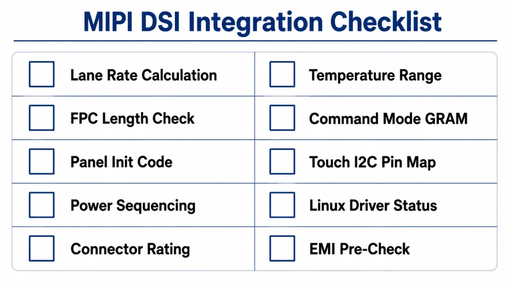
Integration Checklist for Industrial MIPI DSI Display Projects
The following checklist distills the most common failure points encountered in MIPI DSI industrial LCD display projects. Work through it before PCB layout begins.
- Verify DSI host lane count and max lane rate in SoC TRM — do not assume; some silicon variants in the same family differ.
- Calculate required data rate: (H_total × V_total × fps × bpp) ÷ lanes. Add 20% margin for blanking and protocol overhead.
- Confirm FPC length ≤ 30 cm; if longer, specify a MIPI DSI-to-LVDS bridge chip in the BOM from day one.
- Request panel initialization code table from panel vendor before committing to production quantities. Verify it is tested on your specific SoC.
- Check power sequencing timing: AVDD, DVDD, RESET, and MIPI DSI lane enable must follow the panel datasheet sequence to the millisecond.
- Validate connector mating cycles and vibration rating against IEC 60068-2-6 requirements for your application.
- Confirm wide-temperature rating if operating range exceeds 0°C–70°C — standard panel specs, not industrial-grade defaults.
- Check panel GRAM availability if targeting command mode — only specific panels support it, and the host controller must also implement partial update DCS commands.
- Plan for touch controller I2C and interrupt on same FPC — verify pin assignment with panel vendor before PCB layout.
- Identify Linux kernel panel driver status before panel selection — a missing driver adds 2–5 engineer-days to bring-up timeline.
MIPI DSI and the Broader Industrial Display Ecosystem
It would be misleading to discuss MIPI DSI in isolation. Industrial LCD display design increasingly involves decisions about the full display stack: cover glass material, optical bonding vs air-gap assembly, touch technology, backlight driver IC, and enclosure cutout. MIPI DSI is the interface layer of a system that also includes each of these elements.
Optical bonding, for example, is frequently used alongside MIPI DSI panels in high-brightness outdoor or medical applications. The bonding process eliminates the air gap between the cover glass and the LCD panel, reducing surface reflections by up to 75% and improving contrast ratio in high-ambient-light conditions. Kadi Display’s comparison of Optical Bonding vs Air Bonding for Industrial Touchscreens covers the cost, durability, and performance trade-offs relevant to display stack design decisions.
The full display stack — LCD module, touch film, cover glass, FPC, controller board, and enclosure — is described in detail in the industry article on
Industrial Display Stack-Up Design: Integrating LCD, Touch, PCB, FPC, and Enclosure. This is worth reviewing before finalizing mechanical dimensions and FPC routing for any MIPI DSI industrial LCD project.
On the host-platform side, MIPI DSI is one of several interfaces that industrial system designers must evaluate alongside LVDS, eDP, and HDMI for panel PC and kiosk applications. For a full cross-interface comparison including cable length, EMI, power, cost, and ecosystem breadth, refer to the companion article “MIPI DSI vs LVDS vs RGB vs eDP: Which Interface Is Best for Industrial Displays?” which covers the decision matrix in detail.
Selecting a MIPI DSI Industrial LCD Display: Key Specification Checkpoints
When evaluating MIPI DSI display modules for an industrial application, the following specification fields matter most — and are most often misread or ignored in early sourcing:
- Interface lane count: Confirm 1-, 2-, or 4-lane and maximum per-lane data rate match host SoC output.
- Operating temperature range: Distinguish between storage range (typically -30 to +80°C) and operating range (confirm -20 to +70°C minimum for industrial; -40 to +85°C for wide-temp grade).
- Brillo (nits): 300–400 nits for indoor-only; 700–1000 nits for factory floor with overhead fluorescent; 1000–1500+ nits for outdoor-readable.
- Tratamiento de superficie: AG (anti-glare) reduces specular reflection; AR (anti-reflective) coating reduces total reflectance to <1%; AF (anti-fingerprint) for touch surfaces. These are not interchangeable.
- MTBF and lifetime hours (backlight): Industrial panels specify 50,000–70,000 hours MTBF for the LED backlight at 25°C, 50% brightness. Verify derating at maximum operating temperature.
- Touch controller bus: Confirm I2C address, interrupt polarity, and reset line requirements — all must be matched to the host SoC GPIO bank available on the same FPC.
- Connector type and pitch: 0.3 mm vs 0.5 mm pitch ZIF connectors are not interchangeable. Verify mating connector footprint before PCB layout.
Kadi Display’ s industrial TFT-LCD module product range covers sizes from 3.5″ to 21.5″ with MIPI DSI, LVDS, and HDMI interface options, including high-brightness (1400 nit) variants and wide-temperature-grade panels suitable for the specification checkpoints above. Custom display solutions — including custom FPC routing, optical bonding, and interface adaptation boards — are available through the customized display service.
Conclusión
MIPI DSI has earned its place as the standard display interface for industrial LCD applications driven by modern application processors. Its combination of serial-differential signaling, scalable lane bandwidth, low-power states, single-FPC integration, and broad SoC and panel ecosystem coverage addresses the practical requirements of embedded HMI, medical device, portable terminal, and kiosk display design better than any alternative at similar cost.
That said, it is not a plug-and-play interface. Cable length limits, panel initialization complexity, connector fragility, and the operational difference between video mode and command mode all require deliberate engineering choices. The engineers who get the most from MIPI DSI are those who treat it as a protocol to understand — not just a connector to plug in.
Whether you are selecting a panel for a first MIPI DSI project or troubleshooting a bring-up issue on an existing design, the resources linked throughout this article provide a structured starting point. And when the panel, FPC, initialization sequence, and host driver all align — MIPI DSI delivers a clean, efficient, EMI-compliant display link that will serve your industrial product for its entire production lifetime.
Related Resources
- MIPI DSI Timing Table: Pixel Clock, Porches, Sync Width, and Refresh Rate
- MIPI DSI Bandwidth Guide: Lanes, Pixel Clock, and Data Rate per Lane
- MIPI DSI Power Sequencing and Reset Timing Check
- MIPI DSI Command Mode Checklist for Embedded HMI
- MIPI DSI Connector and FPC Pinout Check
- Can You Reuse a MIPI DSI Display Across SBCs and SoMs?
- Industrial Display Stack-Up Design: LCD, Touch, PCB, FPC, and Enclosure
- Optical Bonding vs Air Bonding for Industrial Touchscreens
- Kadi Display — Industrial TFT-LCD Modules
- Kadi Display — Customized Display Solutions
Disclaimer: Technical specifications in this article reflect publicly available standard documents and typical vendor datasheets as of 2026. All interface parameters should be verified against the MIPI Alliance DSI specification v1.3 / DSI-2, MIPI D-PHY specification v2.5, and your specific SoC and panel vendor documentation before use in a product design. No proprietary or confidential vendor information has been used in the preparation of this article.
PREVIOR
No más
Siguiente
MIPI DSI vs LVDS vs RGB vs eDP: Which Interface Is Best for Industrial Displays?
Deja un comentario

Últimos blogs y noticias
- MIPI DSI in Industrial LCD Displays: What Engineers Should Know
- MIPI DSI vs LVDS vs RGB vs eDP: Which Interface Is Best for Industrial Displays?
- PCAP Touch Works on the Bench but Fails After Metal Enclosure Assembly: An Isolation Checklist
- MIPI DSI Works at Low Refresh Rates but Fails at 60 Hz: A Practical Troubleshooting Workflow
- MIPI DSI Works After Power-On but Goes Black After Warm Reboot: Reset and Reinitialization Checks

