




Inicio
-
Blog & Noticias
-
Industrial LCD Drop-In Replacement Checklist: From Hard Stops to Release Evidence
Industrial LCD Drop-In Replacement Checklist: From Hard Stops to Release Evidence
2026-09-14
09:03
Industrial LCD Drop-In Replacement Checklist: From Hard Stops to Release Evidence
DECISION Drop-in, adapter-assisted, or redesign
EVIDENCE Old/new controlled configuration
Start With the Five Hard Stops
DECISION A replacement is “drop-in” only when the existing product can use the new module without changing the mechanical stack, electrical contract, display timing, software behavior, optical acceptance limits, production process, or service configuration. Matching diagonal size, resolution, connector family, or interface name is not enough. If pinout, rails, sequence, timing, mapping, backlight, touch, fit, or firmware support is unknown, classify the part as an unqualified candidate—not a replacement.
First Decide What “Drop-In” Means for This Project
The term is useful only when it describes an outcome. A true drop-in replacement can enter the released assembly without changing the host board, cable, enclosure, firmware, timing profile, backlight driver, touch driver, manufacturing instructions, or acceptance tests. If one of those items changes, the new display may still be the right commercial answer, but it is a controlled substitute or redesign.
That distinction affects schedule and ownership. Purchasing can compare quotes for a true alternate. A controlled substitute needs engineering work, configuration records, revised test coverage, and often new service instructions. A redesign may also require tooling, compliance regression, customer approval, or a transition plan for products already in the field.
Start with the installed population rather than a family-level data sheet. Capture the complete orderable part number and suffix, label photographs, drawing and datasheet revisions, approved deviations, controller-board firmware, EDID or initialization file, touch firmware, cable drawing, and the production test version. If several revisions are in service, sample each known state. The incumbent is not a single rectangle; it is a controlled configuration.
Freeze the Requirement Baseline Before Comparing Candidates
Separate equipment requirements from characteristics inherited from the old panel. An unused mounting tab may be negotiable, while active-area position, backlight-enable polarity, or the direction of a touch tail may be critical. Review the final equipment, field-service method, regulatory file, manufacturing test, and user interface to decide which traits must remain unchanged.
A practical baseline marks every item as mandatory, preferred, negotiable, unknown, or not applicable. It also records the evidence source, revision, unit, condition, tolerance, owner, and verification method. Unknown values become supplier questions or sample tests; they must not be filled from a similar model.
For a broader intake process, use KadiDisplay’s industrial TFT LCD selection guide to define the application, viewing conditions, interface, touch, environment, and customization boundaries before narrowing the work to replacement equivalence.
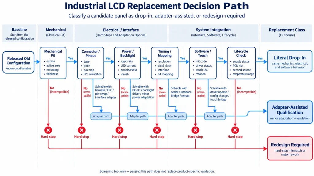
Apply hard stops before scoring softer differences
Do not average a critical mismatch against many minor matches. A wrong supply assignment, unsupported panel protocol, reversed connector contact side, missing backlight compliance range, or unserviceable mechanical interference can disqualify a candidate immediately.
Build One Replacement Delta Record
A replacement decision becomes auditable only when every material old-to-new difference is recorded together with its evidence source, system effect and unresolved uncertainty.
The 25-Point Industrial LCD Replacement Checklist
Use the matrix as a comparison record, not as a list of universal pass values. Each row should point to a drawing, specification, schematic, configuration file, measurement, or test report for both the incumbent and the candidate.
Mechanical equivalence needs a datum overlay
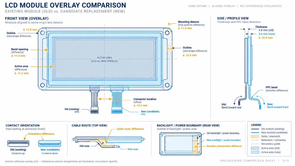
Nominal outline dimensions hide the details that delay tooling: active-area offset, bezel opening, corner radii, tabs, local component heights, FPC exits, connector latch access, and no-pressure zones around COF/COG regions. Overlay both controlled drawings in one coordinate system and build a tolerance stack from supplier tolerances, enclosure datums, gasket or adhesive thickness, fasteners, and thermal expansion.
KadiDisplay’s industrial display stack-up design guide provides the wider context for LCD, touch, cover glass, PCB, FPC, gasket, and enclosure interactions. A panel that fits on an open bench can still fail after gasket compression, cable folding, or bracket preload is introduced.
Connector fit is not electrical compatibility
Verify pitch, circuit count, FPC thickness, stiffener thickness, exposed length, contact side, insertion depth, mating height, current rating, retention, and service access. Pin 1 cannot be inferred from latch direction. If an adapter is proposed, review its drawing, return paths, current capacity, signal integrity, strain relief, assembly control, and part identity.
El FPC connector design guide for MIPI, LVDS, RGB, and touch explains why a continuity check proves only the DC connection. High-speed paths may also need controlled geometry, vendor channel data, simulation, or measurement for the actual lane rate and stack-up.
Interface names conceal product-specific contracts
For LVDS, confirm single or dual link, bit depth, VESA/JEIDA or product-specific mapping, pair polarity, pixel clock, blanking, and cable pin assignment. For eDP, verify lane/rate capability, AUX, HPD, DPCD/descriptor behavior, link training, power sequence, and backlight controls. MIPI DSI requires host/sink roles, D-PHY lanes, mode, timing, packet format, initialization, and platform driver support. HDMI generally feeds a controller board rather than a raw panel.
Utilice el industrial display interface selection guide when the replacement exposes a protocol or architecture change. A pin-conversion cable can reroute contacts; it cannot translate protocol, voltage, timing, mapping, or software behavior.
Qualify Only the Deltas That Can Affect the System
Qualification depth should follow the changed contract and its failure consequence, beginning with non-powered evidence before progressing to electrical and system tests.
Decide Whether an Adapter Solves the Right Problem
An adapter FPC or PCB is appropriate when the underlying electrical and protocol contracts already agree and the remaining difference is controlled interconnection. It can reroute pins, change connector type, or move the cable exit. It may also include level shifting, power regulation, or protocol conversion, but those functions turn it into an active design that needs its own requirements and qualification.
A bridge or controller board is not evidence of equivalence by itself. Confirm direction, endpoint roles, supported timing and formats, clocking, buffering, firmware, EDID/DDC or AUX behavior, power domains, backlight control, latency, protected-content requirements when relevant, lifecycle, and recoverability. Name the resulting architecture honestly so future teams know which files and components are required.
Validate in Layers, Then Release the Configuration
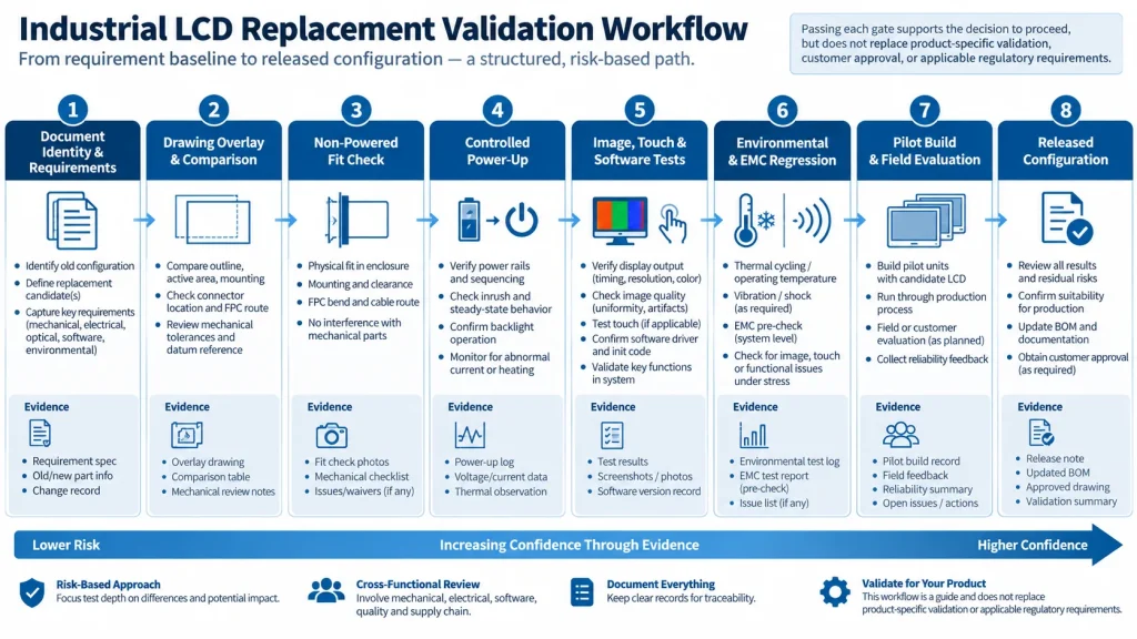
Run inexpensive document checks before modifying hardware or ordering a large sample lot. Bench work should use the production host, released or candidate software, representative content, controlled power cycles, and recorded board/panel identities. Move next to the final mechanical stack, optical and touch evaluation, mission-profile regression, pilot build, and controlled release.
Define acceptance criteria before testing. Record sample part number, suffix, revision, lot, firmware, configuration, instrument, environment, test pattern, and raw observation. “Looks good” cannot support a later change investigation. A powered photograph proves only that one configuration produced an image once.
Release a Configuration, Not a Similar-Looking Panel
The final deliverable is a configuration record that purchasing, manufacturing and service can reproduce without relying on the original engineer’s memory.
Build a Replacement Delta Dossier
A replacement decision becomes easier to review when every difference has one owner, one disposition, and one evidence path. Create the dossier before samples arrive, then update it as documents and test results close uncertainty. This prevents a late discovery—such as a reversed contact side or a different dimming input—from being buried in email.
Classify deltas as identical, different but inside the released system envelope, different and controlled by a verified design change, or unresolved/incompatible. “Equivalent” should not stand alone as a disposition. If a cable adapter corrects the connector location, for example, the dossier should still close pinout, orientation, current capacity, impedance/return path, mechanical retention, assembly error-proofing, and its own revision control.
Also state the approved population. A replacement may be valid for one product revision, software branch, enclosure, temperature grade, or regional configuration and invalid for another. Link the release to exact host board, cable, firmware, mechanical stack and test limits. If old and new displays can be mixed in production or service, define how the system identifies them, chooses any panel profile, and remains diagnosable.
Finally, assign post-release signals. Monitor receiving identity, assembly yield, boot/image/touch failures, optical distributions, repair data, and early field returns for specified lots and a specified review period. Define who can stop shipment and what threshold triggers containment. This turns replacement qualification from a one-time demonstration into controlled product evidence.
Include service and repair in the same boundary. A new display may require a different cable, bracket, firmware profile, calibration, adhesive, gasket or work instruction even when the factory can build it successfully. Define whether field units can accept the replacement, which product serial ranges are eligible, how a technician identifies the installed display, and whether old and new service kits can be interchanged. Validate disassembly, reassembly, sealing, cosmetic protection and post-repair tests where those operations matter.
Review regulatory and customer commitments before release. A display change can alter an assembly’s tested EMC configuration, optical safety assessment, flammability/material declaration, environmental documentation, labeling, or customer-approved BOM. The replacement does not inherit those approvals automatically. Identify the responsible compliance owner, the exact evidence affected, and whether analysis, supplier documentation, delta testing, customer notice or formal reapproval is required. Keep these decisions in the dossier rather than assuming a component-level certificate covers the complete product.
When schedule pressure forces parallel work, separate reversible investigation from release authority. Engineering can inspect samples, prototype an adapter and prepare firmware while sourcing negotiates supply, but production material remains segregated until the named decision owners approve the controlled configuration.
Record that approval date and effective lot explicitly.
RELEASE GATE Approve the candidate only when the old/new delta record is closed, required tests pass against written limits, unresolved differences have named owners, and the released package identifies the module revision, drawings, cables, firmware/configuration, host, power/backlight settings, test method, golden evidence and supplier change rules. Otherwise select “adapter-assisted qualification” or “redesign required.”
For a supplier review, send KadiDisplay the old and proposed part numbers, controlled drawings, host/interface details, pinout, timing, backlight and touch requirements, assembly drawings, failure observations, annual demand and lifecycle expectations through the engineering contact page. Commercial availability and configuration commitments require a current project-specific quotation and agreement.
Primary Sources
- Linux kernel DRM/KMS documentation
- Microsoft display-device design guidance
- Texas Instruments product change notification process
ENGINEERING DISCLAIMER This checklist helps screen and qualify an LCD replacement; it does not establish that any candidate is drop-in, approve an adapter, or transfer the incumbent product’s compliance status. Use the released old and new drawings, exact pinouts, host and backlight schematics, software configuration, and the final product’s validation plan. Stop before connection or power-on if a voltage, direction, sequence, cable identity, or back-power path is unresolved; reassess EMC, environment, service, and customer approvals when the released configuration changes.
Deja un comentario

Últimos blogs y noticias
- Industrial LCD Drop-In Replacement Checklist: From Hard Stops to Release Evidence
- MIPI DSI in Industrial LCD Displays: What Engineers Should Know
- MIPI DSI vs LVDS vs RGB vs eDP: Which Interface Is Best for Industrial Displays?
- PCAP Touch Works on the Bench but Fails After Metal Enclosure Assembly: An Isolation Checklist
- MIPI DSI Works at Low Refresh Rates but Fails at 60 Hz: A Practical Troubleshooting Workflow

