




Полное руководство по разработке с использованием ESP32-S3 + RGB/MIPI-дисплей + GT911 + LVGL
Разработано технической командой Kadi Display | www.kadidisplay.com
Почему комбинация ESP32-S3 + GT911 + LVGL является популярной в промышленном HMI-проектировании?
ESP32-S3 стал одним из наиболее практичных микроконтроллеров для компактных HMI-устройств, поскольку он сочетает в себе Wi-Fi, Bluetooth LE, двухъядерный процессор Xtensa LX7 с тактовой частотой до 240 МГц, поддержку большого объема внешней флэш-памяти/PSRAM и достаточное количество периферийных устройств для отображения информации, что позволяет создавать небольшие и средние по размеру проекты с графическим интерфейсом пользователя. Для инженеров, разрабатывающих недорогие промышленные сенсорные мониторы, это означает, что процессор может выполнять коммуникацию, управляющую логику и современный пользовательский интерфейс LVGL без затрат и сложности полноценной платформы Linux.
Во многих проектах со встроенными дисплеями в качестве интерфейса используется RGB TFT LCD или параллельный интерфейс, а в качестве сенсорного — емкостной контроллер, например GT911, работающий по протоколу I²C. LVGL располагается над аппаратным уровнем и обрабатывает виджеты, экраны, жесты, кнопки, ползунки, графики и сенсорные события. Такая архитектура привлекательна для компактных промышленных терминалов, панелей управления «умного дома», заводских HMI, небольших панелей управления, подобных ПЛК, IoT-шлюзов, интерфейсов зарядных устройств для электромобилей и встроенных экранов мониторинга.
Причина частого упоминания GT911 проста: это зрелый емкостной контроллер мультитач-сенсора, используемый во многих 4,3-дюймовых, 5-дюймовых, 7-дюймовых и специализированных промышленных сенсорных модулях. Он взаимодействует через I²C, поддерживает отправку данных о касании по прерываниям и может быть интегрирован в LVGL с относительно небольшим уровнем драйверов. Ключевым моментом является не простое соединение SDA и SCL; надежный запуск зависит от времени сброса, выбора адреса, сопоставления координат касания и корректной регистрации устройства ввода LVGL.
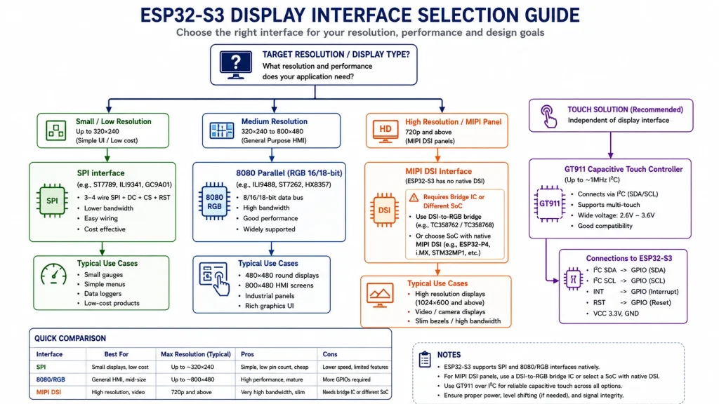
При выборе модуля дисплея важно отметить, что ESP32-S3 обычно хорошо подходит для проектов с SPI, параллельным интерфейсом 8080 и RGB LCD. Встроенный MIPI DSI — это уже другая тема. Kadi Display техническое руководство по поддержке интерфейса MIPI Следует отметить, что ESP32-S3 не имеет встроенного передатчика MIPI DSI; если для проекта действительно необходим MIPI DSI, инженерам обычно требуется мостовая микросхема или процессор другого семейства.
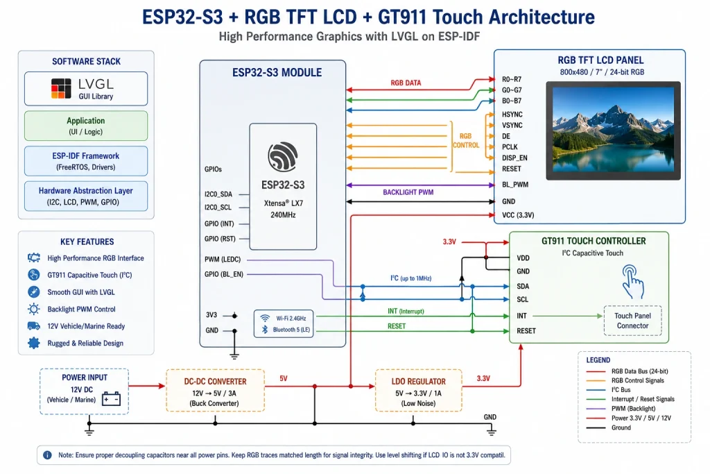
Архитектура оборудования: что с чем фактически соединено?
Типичный проект промышленного дисплея на базе ESP32-S3 состоит из четырех уровней: главный микроконтроллер ESP32-S3, дисплейная панель, емкостная сенсорная панель GT911 и графический интерфейс пользователя LVGL. На главном микроконтроллере работают ESP-IDF, LVGL, драйвер дисплея, драйвер сенсорного экрана, прикладная логика, Wi-Fi или BLE, а иногда и промышленные протоколы связи, такие как MQTT, Modbus, CAN или RS485.
Обычно используется SPI, параллельный интерфейс 8080 или RGB на ESP32-S3. Для проектов HMI класса 800 x 480 распространен RGB, поскольку он может непрерывно передавать данные пикселей через периферийное устройство ЖК-дисплея. Емкостный сенсорный контроллер GT911 подключен через I²C с дополнительными выводами RESET и INT. LVGL не взаимодействует напрямую с GT911. Он вызывает зарегистрированный обратный вызов устройства ввода, и ваш драйвер считывает данные GT911, преобразует их в координаты LVGL и сообщает, нажата или отпущена кнопка на экране.
Это разделение важно. Многие проблемы с сенсорным управлением списывают на LVGL, хотя реальная причина кроется в аппаратной синхронизации, нестабильном питании, неправильных значениях подтягивающих резисторов I²C, некорректной последовательности сброса или несоответствии координат дисплея. Надежный промышленный дисплей на базе ESP32 требует четкого разделения между запуском дисплея, запуском сенсорного экрана и интеграцией LVGL.
RGB против MIPI на ESP32-S3: сначала выберите правильный путь отображения.
Перед написанием кода для GT911 подтвердите следующее: интерфейс дисплеяЭто позволяет избежать одной из самых распространенных ошибок проектирования: выбора дисплейной панели, которую процессор не может поддерживать напрямую. RGB часто является лучшим вариантом для экранов HMI на базе ESP32-S3 в диапазоне от 4,3 до 7 дюймов. Он поддерживает непрерывную потоковую передачу пикселей и подходит для статических панелей управления, страниц настроек, диаграмм и умеренной анимации.
Для промышленного дисплея ESP32 RGB обеспечивает лучшую плавность пользовательского интерфейса, чем SPI, при более высоких разрешениях, но требует больше выводов GPIO, тщательной синхронизации, планирования буфера кадров и достаточной пропускной способности PSRAM. SPI по-прежнему имеет смысл для небольших дисплеев, в то время как параллельный интерфейс 8080 может быть промежуточным вариантом для некоторых модулей. Если выбранный дисплей поддерживает только MIPI, есть три практических варианта: использовать мостовую микросхему, выбрать модуль дисплея с входом RGB/SPI/параллельным входом или перейти на процессор с собственным входом. MIPI DSI поддерживать.
По этой причине наиболее практичный путь разработки в большинстве проектов HMI на базе ESP32-S3 — это ESP32-S3 + RGB LCD + GT911 + LVGL. Он обеспечивает хороший баланс между стоимостью, сложностью разработки, размером дисплея и отзывчивостью пользовательского интерфейса.
Контрольный список проводов для GT911: I²C, RESET, INT, питание и подтягивающие резисторы.
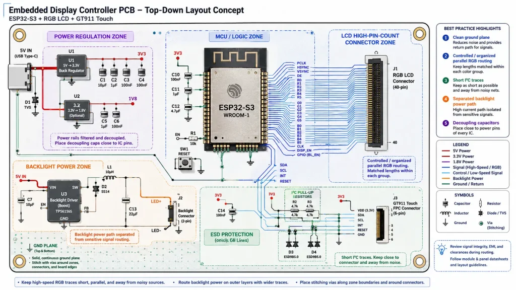
Интеграция GT911 проста только при правильной проводке. Минимально необходимые соединения включают SDA, SCL, RESET, INT, VDD и GND. Линия ШИМ подсветки относится к дисплею/драйверу подсветки и не должна путаться с управлением сенсорной панелью. В промышленных сенсорных мониторах, выпускаемых серийно, линии I²C сенсорного экрана должны быть короткими, заземленными на стабильное заземление и максимально изолированными от источников помех подсветки и переключения RGB-сигнала, насколько это позволяет компоновка.
В надежной конструкции вывод RESET не является необязательным. Он предоставляет хосту контролируемый способ перезапуска контроллера сенсорного экрана, выбора адреса I²C и восстановления после ненормальных состояний запуска. Вывод INT также является не просто линией прерывания. Во время сброса он участвует в выборе адреса на многих модулях GT911. После сброса его можно использовать в качестве входного сигнала для обнаружения новых данных сенсорного экрана.
Подтягивающие резисторы — ещё один скрытый источник неисправностей. Слишком слабые резисторы замедляют фронты сигнала, слишком сильные — приводят к неоправданному увеличению тока. Для коротких дорожек на плате с напряжением 3,3 В обычно используются значения от 2,2 до 4,7 кОм в качестве отправной точки, но правильное значение зависит от ёмкости шины, длины кабеля, разводки гибкого печатного кабеля и от того, используют ли другие устройства I²C ту же шину.
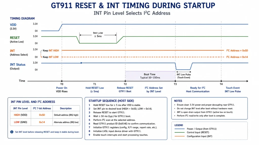
Выбор адреса I²C микросхемы GT911: наиболее распространённая ловушка при запуске системы.
Микросхема GT911 обычно отображается по одному из двух 7-битных адресов I²C: 0x5D или 0x14. Адрес выбирается во время сброса с помощью вывода INT. Именно здесь начинаются многие случаи неудачной инициализации GT911. Инженеры сканируют шину I²C, не обнаруживают устройства и предполагают, что контроллер неисправен. В действительности, возможно, синхронизация INT/RST выбрала другой адрес, или вывод INT может находиться в плавающем состоянии во время сброса.
Типичная процедура сброса выглядит следующим образом: настроить RESET и INT как выходы, установить INT в высокое или низкое состояние для выбора целевого адреса, установить RESET в низкое состояние, подождать, отпустить RESET, дождаться загрузки контроллера, затем вернуть INT в режим входа, если используется режим прерывания. Не следует предполагать, что все панели GT911 используют одинаковое поведение сброса. Некоторые модули FPC имеют подтягивающие резисторы, некоторые — нет, а некоторые производители дисплеев используют разную схему трассировки INT.
Наиболее безопасный подход заключается в реализации обоих адресов в драйвере и сканировании обоих на ранних этапах отладки. Если первое сканирование I²C обнаружит 0x5D, зафиксируйте это значение в производственном драйвере только после подтверждения корректного поведения при холодной загрузке, программном сбросе, выключении и включении питания, а также при прошивке микропрограммы.
Структура проекта ESP-IDF для LVGL + GT911
В чистом проекте ESP32-S3 + LVGL файлы должны быть разделены по областям ответственности. Драйвер дисплея должен инициализировать RGB-дисплей, буфер кадров, подсветку и функцию обратного вызова LVGL для сброса состояния дисплея. Драйвер сенсорного экрана должен инициализировать I²C, сбросить GT911, считать координаты касания, очистить регистры состояния GT911 при необходимости и вернуть чистое состояние сенсорного экрана в LVGL.
В практическую структуру проекта могут входить файлы app_main.c, display_rgb.c, touch_gt911.c, lvgl_port.c и папка UI. Разделение этих слоев ускоряет отладку, поскольку каждая проблема имеет определенное местоположение. Если дисплей не обновляется, начните с драйвера дисплея. Если контроллер сенсорного экрана не обнаружен, начните с I²C и сбросьте синхронизацию. Если сенсорный ввод работает, но кнопки не реагируют, проверьте регистрацию устройства ввода LVGL.
Ввод данных в LVGL ожидает функцию обратного вызова, которая сообщает о состоянии ввода. Ваш драйвер GT911 считывает точку, преобразует её в текущую ориентацию дисплея и передаёт результат в LVGL как PRESSED или RELEASED. LVGL должен получать координаты в той же ориентации, что и буфер дисплея. Если ЖК-дисплей повернут, зеркально отображен или установлен вверх ногами, координаты касания необходимо преобразовать перед передачей их в LVGL.
Чтение данных сенсорного экрана GT911: уровень драйвера
Процедура чтения данных с GT911 обычно следует простому шаблону: чтение регистра состояния сенсорного экрана, проверка наличия допустимой точки касания, чтение данных координат, преобразование исходных координат в координаты дисплея, сброс флага состояния при необходимости и возврат состояния нажатия/отпускания в LVGL. Точные имена регистров и расположение байтов всегда следует проверять по руководству по программированию GT911 и конфигурации модуля конкретного производителя сенсорной панели.
В реальной разработке первоочередная задача — не интеграция жестов. Первоочередная задача — надёжно выводить исходные координаты. Коснитесь четырёх углов и центра экрана. Убедитесь, что значения изменяются стабильно и что максимальные значения соответствуют активной области датчика. Только после стабилизации исходных данных следует добавлять отображение LVGL, фильтрацию и поведение жестов.
Избегайте копирования случайного кода драйвера без проверки разрешения панели, ориентации координат и выбора адреса I²C. Драйвер, написанный для панели 1024 x 600, может скомпилироваться для панели 800 x 480, но при этом выдавать зеркальные, масштабированные или выходящие за пределы допустимого диапазона координаты.
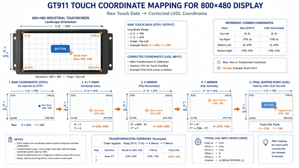
Сопоставление координат: когда тактильные ощущения работают, но неприятны.
Одна из самых неприятных проблем с сенсорным управлением LVGL возникает, когда GT911 сообщает о точках касания, но координаты не совпадают с отображаемыми. Пользователь нажимает кнопку слева, а LVGL реагирует справа. Верхняя и нижняя части экрана перепутаны местами. X и Y поменяны местами. Реагирует только часть экрана. Обычно это проблемы с системой координат, а не сбои в работе сенсорного контроллера.
Контроллер дисплея, настройка поворота LVGL, физическая ориентация ЖК-дисплея и конфигурация GT911 должны совпадать. Если они не совпадают, примените сопоставление координат после считывания данных из GT911, но до передачи их в LVGL. Распространенные преобразования включают в себя x = ширина – 1 – x, y = высота – 1 – y, замену X и Y местами или применение масштабирования и смещения.
При разработке встроенного графического интерфейса пользователя производственного качества не следует слепо прописывать преобразования вручную. Выведите необработанные координаты GT911 в четырех углах панели. Затем определите, связана ли проблема с заменой, зеркальным отображением, масштабированием или смещением. Этот простой тест может сэкономить часы ошибочной отладки LVGL.
Порядок инициализации: надежная последовательность запуска
Для стабильной работы проекта на ESP32-S3 с GT911 LVGL порядок инициализации имеет значение. Надежная последовательность действий следующая: инициализация линий питания и GPIO подсветки, но без включения подсветки; инициализация I²C; настройка выводов RESET и INT микроконтроллера GT911; выполнение аппаратного сброса GT911 и выбора адреса; сканирование или зондирование GT911 по адресам 0x5D и 0x14; инициализация RGB LCD-панели и буфера кадров; инициализация драйвера тактового сигнала и дисплея LVGL; регистрация устройства сенсорного ввода LVGL; и, наконец, включение подсветки после первого действительного кадра.
Это позволяет избежать распространенной проблемы, с которой сталкиваются пользователи: яркий белый или шумный экран появляется до того, как пользовательский интерфейс будет готов. Также это разделяет запуск сенсорного экрана и запуск дисплея, что упрощает отладку. Неправильная синхронизация RGB может вызывать мерцание, смещение изображений, разрывы или нестабильную частоту обновления дисплея, которая выглядит как проблема LVGL. Значения синхронизации ЖК-дисплея должны соответствовать техническим характеристикам панели, включая активное разрешение, тактовую частоту пикселя, ширину синхронизации и настройки Porch.
В промышленных HMI-устройствах контролируемый запуск также улучшает воспринимаемое качество. Устройство, которое загружается с чистым экраном с логотипом, а затем переходит в приложение, ощущается более надежным, чем устройство, которое мигает случайными пикселями перед запуском графического интерфейса.
Распространенные проблемы с GT911 + LVGL и способы их решения
Ошибка инициализации GT911 обычно означает, что хост не может связаться с контроллером. Начните с проверки питания, заземления, синхронизации сброса, состояния INT, подтягивающих резисторов и адреса I²C. Во время запуска уменьшите частоту шины до 100 кГц. Просканируйте сигналы 0x5D и 0x14. По возможности проверьте форму сигнала RESET с помощью осциллографа или логического анализатора.
Проблема с неработающим сенсорным экраном GT911 в LVGL может возникнуть даже при работающей связи по I²C. В этом случае убедитесь, что LVGL зарегистрировал устройство ввода, вызывается функция обратного вызова чтения, драйвер корректно возвращает PRESSED и RELEASED, а координаты находятся в пределах разрешения экрана. Добавьте логи в функцию обратного вызова перед заменой оборудования.
Неправильные координаты касания обычно требуют сопоставления. Ложные двойные щелчки или фантомные касания часто возникают из-за шума в линиях I²C, слабого заземления, помех от драйвера подсветки, воды на защитном стекле или недостаточной фильтрации. Разрывы изображения RGB во время обновлений LVGL обычно не связаны с GT911; они часто указывают на стратегию буферизации кадров, пропускную способность PSRAM или синхронизацию ЖК-дисплея.
Планирование производительности: с чем ESP32-S3 может справиться в разумных пределах
ESP32-S3 — мощный микроконтроллер, но это не настольный графический процессор. Экран с разрешением 240 x 320 пикселей (SPI) — это просто. Панель с разрешением 480 x 480 пикселей — вполне приемлемая. Промышленный HMI с разрешением 800 x 480 пикселей (RGB) практичен при тщательном планировании PSRAM и буферов. Более высокие разрешения могут работать в некоторых случаях, но они становятся чувствительными к пропускной способности и оставляют меньше места для Wi-Fi, анимации, регистрации данных и задач связи.
Для промышленных HMI-интерфейсов разрешение 800 x 480 часто является практичным верхним пределом комфорта для проектов на базе ESP32-S3 RGB. Оно хорошо подходит для панелей управления, экранов контроля и экранов состояния, особенно если пользовательский интерфейс избегает полноэкранной анимации и видео. По возможности используйте частичные обновления. Избегайте ненужной прозрачности и больших анимированных виджетов. Делайте переходы между экранами простыми. Цель — надежная панель управления, а не демонстрация анимации в стиле смартфона.
Если для приложения требуется разрешение 1024 x 600 или выше, высокая частота кадров, видео или сложные диаграммы, следует подумать, какой вариант будет лучше в долгосрочной перспективе: процессор, совместимый с Linux, или платформа с поддержкой MIPI.
Заметки по промышленному дизайну: за пределами демонстрационной доски
Демонстрация рабочего стола — это не то же самое, что... емкостный сенсорный промышленный дисплейДля развертывания в полевых условиях следует учитывать защиту от электростатического разряда, защитное стекло, оптическое соединение, управление подсветкой, стабильность питания, схему размещения для защиты от электромагнитных помех, фиксацию разъемов, тепловую конструкцию и поддержку на протяжении всего жизненного цикла. Сенсорные панели являются интерфейсами, ориентированными на человека, поэтому области разъемов и защитного стекла должны быть защищены от электростатического разряда.
Толщина защитного стекла, твердость, антибликовое/антибликовое/антифильтрационное покрытие и способ склеивания влияют как на долговечность, так и на чувствительность сенсорного экрана. Для дисплеев, используемых на открытом воздухе или с высокой яркостью, оптическое склеивание улучшает читаемость и механическую прочность. При использовании ШИМ-диммирования следует избегать видимого мерцания, а для дисплеев, используемых на открытом воздухе, следует учитывать регулировку яркости в зависимости от окружающего освещения.
Особое внимание следует уделить стабильности питания. ESP32-S3, RGB LCD-дисплей, подсветка и сенсорная панель не должны использовать один и тот же слабый регулятор напряжения, который может давать сбои во время передачи данных по Wi-Fi или включения подсветки. Линии RGB постоянно переключаются, поэтому следует избегать контакта I²C сенсорного экрана с высокоскоростными трассами дисплея и контурами питания подсветки. Промышленная надежность обеспечивается именно этими деталями, а не только самой платой разработки.
Резюме
Подключение емкостной сенсорной панели GT911 к LVGL на ESP32-S3 не представляет сложности, но легко допустить ошибки, если проект начинается со скопированного кода драйвера вместо четкого плана аппаратной части. Надежный путь заключается в том, чтобы сначала выбрать совместимый с ESP32-S3 интерфейс дисплея, обычно RGB для экранов HMI среднего размера, затем активировать GT911 с помощью управляемой последовательности сброса I²C, подтвердить адрес, проверить необработанные координаты касания, сопоставить их с ориентацией ЖК-дисплея и, наконец, зарегистрировать функцию обратного вызова LVGL для ввода.
В промышленных проектах настоящая работа начинается после запуска демонстрации. Защита от электростатического разряда, стабильность электропитания, промышленные TFT ЖК-модулиНадежность изделия в полевых условиях определяется синхронизацией дисплея, пропускной способностью PSRAM, уровнем шума подсветки, фильтрацией сенсорного экрана и механической интеграцией. Продуманная архитектура ESP32-S3 + RGB LCD + GT911 + LVGL может поддерживать множество компактных промышленных HMI-приложений, но только если интерфейс дисплея, контроллер сенсорного экрана и порт LVGL спроектированы как единая система.
Таблица подключения проводов GT911
Матрица поиска и устранения неисправностей
Примечания к источнику
Для ознакомления с возможностями микроконтроллера и архитектурой RGB-ЖК-дисплея использовались информация о продукте Espressif ESP32-S3 и документация к RGB-ЖК-дисплею ESP-IDF.
Адрес I²C микросхемы GT911, поведение при сбросе и концепции контроллера сенсорного экрана следует проверять в соответствии с руководством по программированию GT911 и конфигурацией конкретного производителя сенсорной панели.
Концепции обратного вызова устройств ввода LVGL были согласованы с официальной документацией по устройствам ввода LVGL.
Технические страницы Kadi Display использовались в качестве рекомендуемых целевых площадок для внутренних коммуникаций по интерфейсу MIPI, выбору интерфейса дисплея, промышленным TFT LCD-модулям и интеграции промышленных емкостных сенсорных дисплеев.
Отказ от ответственности
Предупреждение: Данная статья предназначена для инженерного образования и планирования SEO/GEO-контента. Поведение регистров GT911, время сброса, формат координат и выбор адреса I²C следует проверять по официальному руководству по программированию GT911 и техническому описанию конкретного производителя сенсорной панели. Производительность дисплея ESP32-S3 зависит от версии ESP-IDF, конфигурации PSRAM, синхронизации ЖК-дисплея, стратегии буферизации кадров, разводки печатной платы и рабочей нагрузки приложения. Торговые марки, включая Espressif, ESP32, LVGL, Goodix и Kadi Display, принадлежат их соответствующим владельцам.


