




Главная
-
Блог & Новости
-
LCD Ribbon Cable Connector Guide: How to Specify ZIF, FFC/FPC, Pitch, and Contact Direction
LCD Ribbon Cable Connector Guide: How to Specify ZIF, FFC/FPC, Pitch, and Contact Direction
2026-08-03
12:42
LCD Ribbon Cable Connector Guide: How to Specify ZIF, FFC/FPC, Pitch, and Contact Direction
A practical selection and validation reference for industrial display engineers, buyers, and production teams
An LCD ribbon cable connector only works when its mechanical envelope, contact geometry, cable construction, and electrical assignment agree. This guide shows how to specify the complete connection, avoid ambiguous front-flip/back-flip terminology, and verify a mating system before PCB release or volume purchasing.
The 30-Second Answer: What Must Match?
Short answer: An LCD ribbon cable connector is compatible only when the connector series and cable match in pitch, circuit count, exposed-contact side, insertion thickness, stiffener geometry, insertion depth, and pad layout. The actuator style, PCB footprint, current rating, temperature range, cable exit path, and access for assembly must also suit the product.
“30-pin 0.5 mm ZIF connector” is incomplete. It omits contact position, accepted cable thickness, actuator orientation, mated height, footprint, and exact series. Parts that share pitch and circuit count can still be mechanically or electrically incompatible.
Treat the display FPC, connector, PCB footprint, enclosure, and cable support as one system. Start with the display supplier’s recommended mating part. Compare complete drawings and validate samples before approving an alternative.
Compatibility rule — A connector is not “equivalent” because its headline specifications match. Equivalence requires the same electrical function, cable acceptance geometry, PCB footprint, operating limits, and validated assembly behavior.
FFC vs. FPC: Construction Is Different; Compatibility Is Dimensional
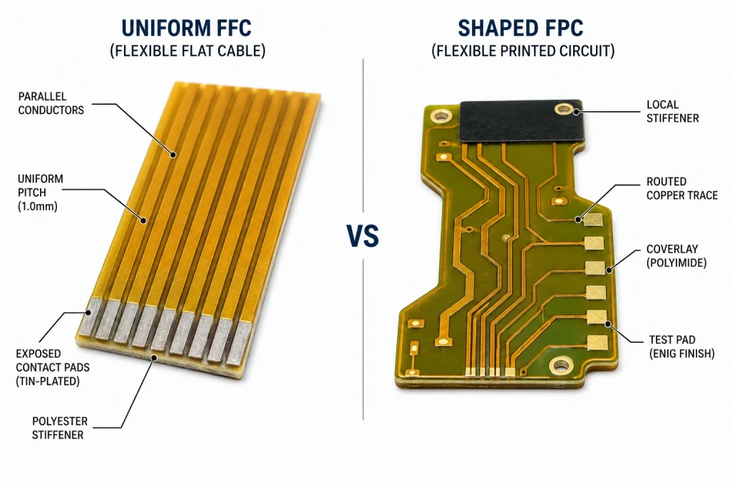
FFC means flat flexible cable: parallel flat conductors laminated between insulating films, typically with reinforcement at the termination. FPC means flexible printed circuit: copper circuitry patterned on a flexible substrate, often with shaped routing, coverlay openings, stiffeners, or multiple layers. The terms describe construction, not a guaranteed connector interface.
Many connector families are qualified for both FFC and FPC, which is why connector catalogs often say “FFC/FPC.” Compatibility still depends on the exact cable specification. An FPC may have a local stiffener, tabs, or a pad geometry that an otherwise similar FFC does not. Conversely, a standard FFC may fit a connector that rejects a thicker custom FPC.
Related Kadi Display reference: FFC vs. FPC flexible cable technologies explains the broader construction and application differences.
ZIF, LIF, Front Flip, Back Flip, and Slider: Use the Datasheet’s Mechanism
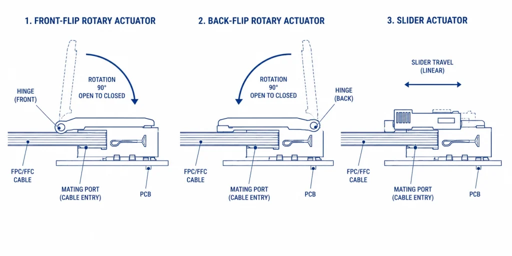
ZIF means zero insertion force: an actuator opens the contacts for low-force cable insertion, then closes to apply contact pressure. LIF and non-ZIF designs require more insertion force. These terms do not define the contact side.
Front/back flip locates a rotary actuator: front at the mating port, back opposite it. Neither means slider or stuffer, which describes translating motion.
Terminology correction — Do not write “back flip (slide-lock).” Back flip identifies actuator location; slider identifies actuator motion. Always carry the exact connector series and operation drawing into the BOM and assembly instruction.
Top Contact vs. Bottom Contact: Define the Connector, Then Orient the Cable
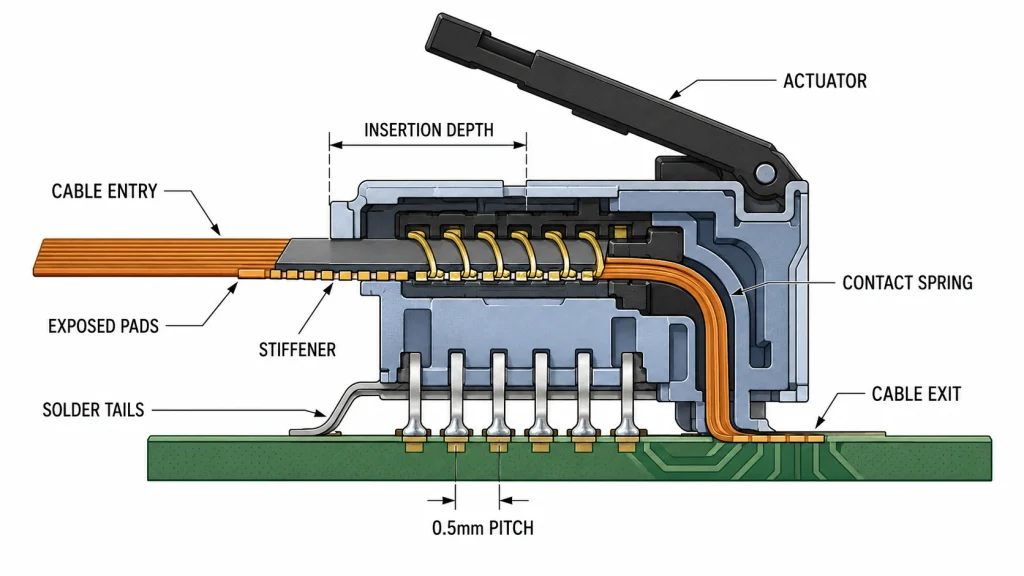
Top contact and bottom contact are connector properties in the manufacturer’s drawing. A top-contact connector engages the exposed cable pads from the upper side of the mating slot; a bottom-contact connector engages them from the lower side. The cable pads must face the connector’s contact springs. If they face the insulated side, the latch may close normally while the circuit remains open or intermittent.
Avoid definitions based only on “toward the PCB” or “visible to the operator.” Those visual shortcuts can fail with vertical connectors, inverted boards, double-sided assemblies, or inconsistent drawing views. Use the connector’s contact-position field and section view, then verify the display FPC pad side in the module drawing.
Common invisible failure — A reversed flex can feel fully seated and locked. If the display is blank or touch is dead after assembly, confirm pad orientation and insertion depth before changing firmware or replacing the panel.
If the mating system truly requires orientation independence, select a connector explicitly rated for dual contact and validate it with the intended cable. Do not solve a contact-direction mismatch by scraping insulation, folding the flex sharply, or forcing the cable into a connector not specified for that construction.
Pitch, Circuit Count, FPC Thickness, and Stiffener Geometry
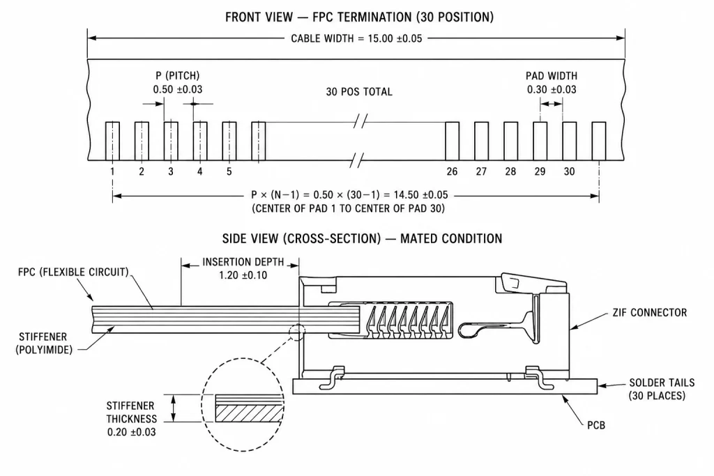
Pitch is the center-to-center spacing of adjacent contacts. Circuit count is the number of electrical positions. Both must match exactly, but neither describes the cable’s total width by itself. For a straight single-row contact field, the distance between the centers of the first and last contacts is pitch × (circuit count − 1); the overall cable and connector widths add edge margins defined by their drawings.
Measurement rule — Measure pitch over several contacts whenever possible, then divide the measured span by the number of intervals. Measuring one fine-pitch gap with a low-resolution ruler can turn 0.40 mm into 0.50 mm and create a costly false match.
Available pitch does not make a safe default. Select the display and exact connector together. For incoming inspection, use a gauge, microscope image, or approved dimensional sample.
Interface Signals and Pin Count: Never Select a Connector from the Bus Name Alone
The display interface influences the number and type of conductors, but it does not standardize the connector pin count. Ground returns, power rails, backlight control, reset, identification pins, touch signals, and unused positions vary by module. A 30-position connector on one panel can have a completely different pinout from a 30-position connector on another.
For system-level interface selection, see Kadi Display’s MIPI, RGB, and LVDS display interface selection guide. It complements—rather than replaces—the module-specific pinout and connector drawing.
Signal-integrity rule — A flex cable is part of the interconnect. For LVDS or MIPI DSI, preserve pair geometry, reference return paths, polarity, and breakout symmetry. A mechanically compatible connector can still fail electrically at operating data rate.
Reliability Is Series-Specific: Cycles, Vibration, Temperature, and Cable Support
Fine-pitch ZIF connectors are not automatically high-cycle parts. Published compact 0.5 mm examples commonly specify about 10–20 mating operations, not thousands. Use the exact part’s durability test and conditions.
Actuator style alone does not determine vibration resistance. Tabs, locks, housing, hold-downs, cable routing, and external support can matter more than front flip or back flip.
Temperature qualification is system-level: connector, flex, adhesive, display, backlight, and enclosure must all survive the profile. A high-rated connector does not upgrade a lower-rated cable or panel.
Do not use the actuator as strain relief — Support the cable so enclosure vibration and service pulls are not transferred into the connector. Adhesive, tape, clamps, or silicone must be material-compatible, reworkable as required, and validated for contamination, cure chemistry, temperature, and stress. Do not prescribe generic hot-melt or RTV without process approval.
Related diagnostic reference: LCD connector failure modes—ZIF lock, FPC cable, solder joints, and contact wear.
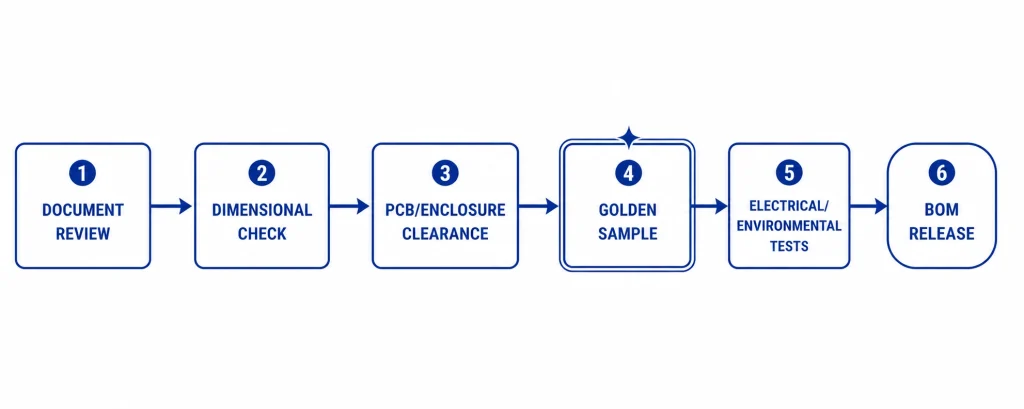
Procurement and Validation Workflow Before PCB Release
Problem: Most connector mistakes enter the project as an incomplete line item.
Ответ: Freeze the mating-system record, not just the connector description. The record should include the display drawing revision, exact connector part number, FPC termination detail, PCB footprint, assembly method, enclosure routing, and validation evidence.
- Obtain the latest display mechanical drawing, FPC pinout, and supplier-recommended mating connector.
- Confirm exact connector manufacturer, series, suffix, packaging code, lifecycle status, and approved alternates.
- Compare pitch, circuit count, contact position, cable width, insertion thickness, stiffener, tabs, and insertion depth.
- Verify the PCB land pattern, connector orientation, component keep-out, actuator travel, and enclosure access.
- Review voltage, current per contact, temperature, contact resistance, insulation, and mating-durability ratings.
- Check high-speed pair mapping, polarity, grounds, power sequencing, backlight current, and touch/ESD paths.
- Build a golden-sample set using the production-intent display, connector, PCB, cable routing, and enclosure.
- Inspect seating and latch closure, then run display, touch, backlight, thermal, vibration, and service-rework checks appropriate to the product.
- Capture photos, measurements, approved drawings, and functional results in the BOM release package and incoming-inspection plan.
Golden-sample rule — Approve the physical mating system before volume ordering. A sample can reveal drawing interpretation errors, incomplete seating, actuator-clearance problems, and cable-routing stress that a spreadsheet comparison will not.
FAQ: LCD Ribbon Cable Connector Questions
Can a 0.5 mm, 30-pin ZIF connector replace any other 0.5 mm, 30-pin part?
No. Match contact position, cable thickness, stiffener/tabs, insertion depth, actuator, PCB footprint, height, ratings, and assembly access—not only pitch and circuit count.
Is a back-flip connector the same as a slide-lock connector?
No. Back flip locates a rotary actuator opposite the cable entry; slider means translating motion. Use the exact series operation drawing.
How do I identify top contact or bottom contact?
Read the contact-position field and cross-section, then face the flex pads toward the spring contacts. Do not infer orientation from “up” or “down” alone.
Can an FFC mate with an FPC connector?
Often yes, if the exact series is qualified for FFC/FPC and the cable meets its dimensional, material, electrical, and pad-layout requirements.
How many times can a ZIF connector be opened and closed?
Use the exact series rating. Compact examples often specify about 10–20 operations; treat the value as a qualification limit, not a guessed service target.
Why does a display stay blank even though the ribbon cable is locked?
Check contact side, insertion depth, latch, pinout, power, reset, and backlight. A reversed or partial flex can lock while circuits remain open.
Engineering source notes
Actuator orientation and dual-contact examples: Hirose FH69 technical overview. Front-flip bottom-contact example: Hirose FH52 series. Portfolio terminology and pitch range: Molex FFC/FPC connector portfolio. Top/bottom contact and actuator terminology: TE Connectivity FPC guide.
Interface architecture references: MIPI D-PHY working group и Texas Instruments flat-panel LVDS application report. Example 0.5 mm connector durability data: Molex 503480 series product data.
Product Reference & Engineering Support — For industrial TFT LCD modules with confirmed FPC pinouts, recommended mating connector part numbers, golden-sample support, and OEM/ODM options, visit kadidisplay.com/products or contact Sales@sz-kadi.com.
Product range: industrial TFT LCD modules and custom display solutions
Disclaimer: Representative engineering guidance only—not legal, safety, or compliance advice. Verify dimensions, ratings, durability, and procedures against exact manufacturer datasheets, display/PCB drawings, enclosure design, production controls, and physical samples. Third-party trademarks belong to their owners.
Предыдущий
MIPI, LVDS, RGB, and Touch FPC Connector Design Guide
Следующая
MIPI DSI Display Bring-Up Checklist: Eight Evidence Gates
Оставить комментарий

Последние блоги и новости
- MIPI DSI Display Works at Room Temperature but Fails After Warm-Up: A Troubleshooting Workflow
- How to Choose an LCD Controller Board: Architecture, EDID, Timing and Latency
- Industrial Display RFQ Checklist: Build a Supplier-Ready Evidence Package
- Industrial LCD Drop-In Replacement Checklist: From Hard Stops to Release Evidence
- MIPI DSI in Industrial LCD Displays: What Engineers Should Know
Блог и новости
-
 TN против IPS2024-7-9
 -
TN против IPS2024-7-9

