Display Interface Selection Guide
2026-05-02
11:11
Display Interface Selection Guide
MIPI Display · RGB Display · LVDS Display — Origins, Specs, and How to Choose
By Kadi Display Technical Team | www.kadidisplay.com | Industrial Display Technology
Why Interface Choice Is the First Decision, Not an Afterthought
Every embedded display project eventually hits the same question: which interface? And it is a harder question than it looks, because the answer changes depending on the size of the panel, the processor platform, the cable run length, the production budget, and the noise environment the device will live in. Get it wrong early and you end up either re-spinning the PCB or compromising on frame rate and resolution in ways that are very hard to fix later.
This guide covers all the major display interfaces that exist today — where they came from, what they are actually good at, and when to pick one over another. The emphasis is on industrial and embedded applications: RGB parallel, LVDS, and MIPI DSI get the most depth here because they are the interfaces you will encounter on almost every serious HMI project. SPI, eDP, HDMI, and VGA are covered briefly because they are either too limited or too application-specific to warrant the same treatment for an industrial audience.
A Map of Every Interface on the Market
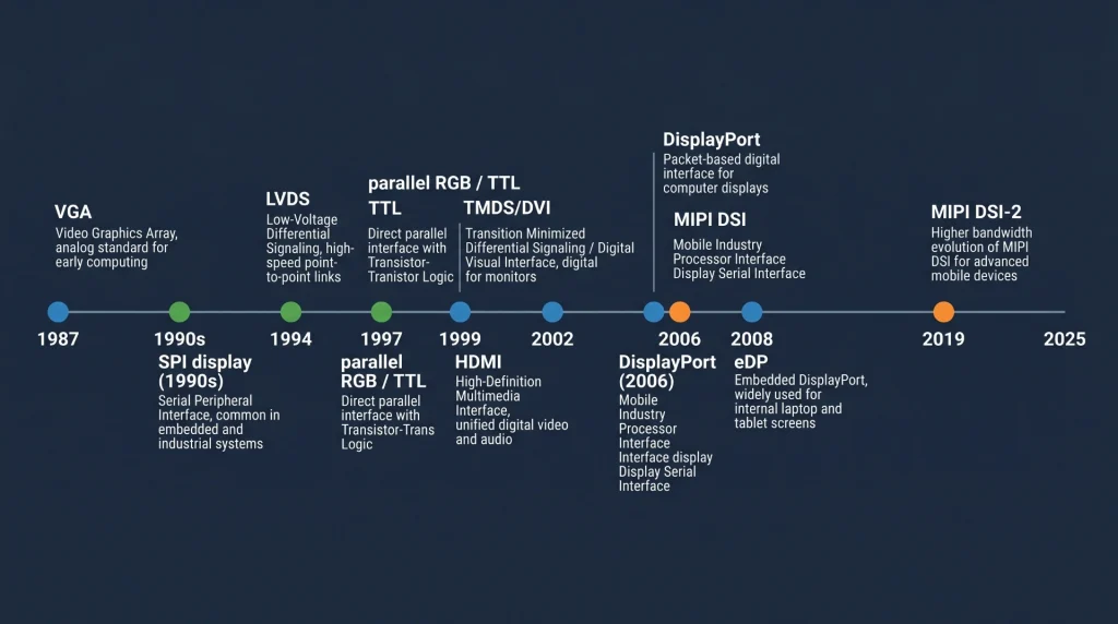
Before diving into the main three, it is worth having a single reference that shows where everything sits. The table below summarises every major display interface family, the era it came from, and what it is typically used for today.
Display Interface Quick Reference
A few things worth noting here. VGA is included because you still encounter it in legacy industrial equipment replacement projects — old CNC controllers, factory floor terminals, and medical devices from the 2000s that need display upgrades. eDP is the standard on modern x86 compute modules (Intel NUC, Raspberry Pi CM4 carrier boards, and most commercial panel PCs) but is rarely designed into custom embedded hardware from scratch because it requires specific timing controller chips. HDMI and DisplayPort are largely consumer interfaces; they appear in embedded designs when the display is an off-the-shelf monitor rather than an integrated panel.
Industry data point: According to market analysis from display supply chain research, LVDS-interface panels continue to account for more than 35% of industrial monitor shipments globally as of 2024, despite being a mature technology. The installed base of LVDS-compatible hardware is simply too large to displace quickly.
RGB Parallel Display Interface — The Workhorse of Mid-Size Industrial Panels
Where It Came From
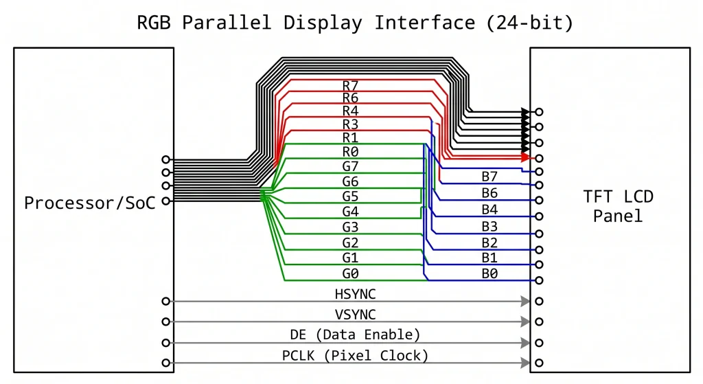
The parallel RGB interface — sometimes called TTL parallel, DPI (Display Parallel Interface), or simply “parallel LCD” — grew out of the simple logic: if you have enough GPIO pins and fast enough logic, you can drive a panel pixel by pixel, line by line, using separate wires for each bit of the red, green, and blue channels. The idea is as old as CRT raster scanning. What changed in the late 1990s was that LCD panel manufacturers started standardising on a 24-bit parallel input (8 bits each for R, G, B) with HSYNC, VSYNC, DE (data enable), and a pixel clock — essentially freezing one approach that everyone could build to.
This became the RGB888 interface that powers the majority of industrial TFT LCD modules in the 4-to-12-inch range today. A 7-inch 800×480 panel at 60 Hz, for instance, needs a pixel clock of around 33 MHz, which is comfortably within the capabilities of general-purpose MCU/MPU GPIO output stages. On an STM32H7 or an NXP i.MX6, the LCD-TFT Display Controller (LTDC) hardware block handles all the sync timing automatically — you just configure the resolution, clock, and front/back porch parameters, point the LTDC at a frame buffer in SDRAM, and the hardware streams pixels continuously without CPU involvement.
Bandwidth and Practical Limits
The maths is straightforward. An 800×480 display at 60 fps with 24-bit colour and standard sync overhead needs about 27 MHz pixel clock. A 1024×600 panel at 60 fps needs around 48 MHz. A full 1280×800 WXGA panel at 60 fps pushes to roughly 71 MHz. These are achievable with careful PCB routing, but the parallel bus starts fighting back: 24 data lines plus 4 control lines is 28 traces that all need similar propagation delay to avoid image artefacts. Beyond about 10 cm of trace length, you need to think about matched-length routing, which adds layout complexity and PCB area.
Beyond 1280×800, the parallel RGB interface becomes impractical. The pixel clock exceeds 80–100 MHz, and the simultaneous switching of 24 lines becomes a serious EMI concern. That is the natural boundary where engineers historically moved to LVDS, and more recently to MIPI DSI or eDP.
Where RGB Still Makes Sense
Despite the limitations, RGB parallel is not going anywhere in the industrial display market. The ecosystem of processors with LTDC or equivalent hardware is enormous — STM32 F4/H7, NXP i.MX6/7/8, Allwinner A series, Rockchip RK35xx, TI AM335x/AM5xx all support parallel RGB natively. Panel cost is competitive. And for anything up to 7–10 inches at 60 fps, the interface is completely adequate.
Recommended products: Industrial TFT LCD Display Modules — Kadi Display — A range of 4.3-inch to 10.1-inch RGB and MIPI TFT LCD panels with optional capacitive touch, wide operating temperature, and high-brightness options from 400 to 1000 nit.
LVDS Display Interface — The Reliable Choice for Large Industrial Panels
The Engineering Behind It
Low Voltage Differential Signalling (LVDS) was formalised in ANSI/TIA-644 in 1994, and the display-specific variant — sometimes called OpenLDI (Open LVDS Display Interface) — emerged from a collaborative effort among panel makers in the late 1990s. The core idea is simple but clever: instead of sending one bit per wire at high voltage (as parallel RGB does), LVDS sends each bit as a differential pair running at a much lower voltage swing — typically 350 mV peak differential, compared to 3.3 V for TTL signals.
That lower swing makes LVDS dramatically less susceptible to noise and electromagnetic interference, and it also means the bus can run much faster per pair: a single LVDS lane can carry serialised data at rates from 100 Mbps up to around 1.5 Gbps, depending on the specific silicon implementation. A typical single-channel LVDS link (1 clock pair + 4 data pairs = 10 wires total) running at 700 Mbps per pair carries the equivalent of a 24-bit RGB bus running at 65 MHz — which covers a 1024×768 panel at 60 fps easily.
Single-Channel vs. Dual-Channel LVDS
For panels up to around 1024×768 or 1280×800 at 60 fps, single-channel LVDS (4 data pairs + 1 clock pair) is sufficient. For larger panels — 1920×1080 Full HD at 60 fps, 1280×1024 SXGA at 75 Hz, or anything pushing past about 110 MHz pixel clock equivalent — dual-channel LVDS splits the data across two banks of 4+1 pairs, effectively doubling the bandwidth. The connector goes from around 20 pins to 30–40 pins, but the signal integrity advantages of LVDS over parallel RGB are fully preserved.
One practical note that catches engineers out: LVDS uses a serialiser on the processor side and a deserialiser built into the panel’s timing controller. This means the raw LVDS signal is not directly generated by the processor’s GPIO — you need a dedicated LVDS transmitter chip (such as the Texas Instruments SN65LVDS84 family, or equivalent), or a processor with a built-in LVDS output block (found in NXP i.MX6/8, Rockchip RK3399, and several other application processors). Budget the BOM cost and PCB space for that transmitter if your SoC does not have one on-chip.
Cable Length and EMI Advantages
This is where LVDS genuinely shines versus RGB parallel. A well-terminated LVDS link can run reliably across 50–100 cm of differential cable — sometimes more, depending on the specific panel timing controller and transmitter silicon. That is the reason nearly every industrial panel PC, embedded vision system, and medical imaging terminal uses LVDS for its main display link: the display module can be mounted on the front of an enclosure while the compute board sits at the back, with a 30–50 cm cable between them.
Field experience note: A common mistake in LVDS designs is using single-ended ground return for the cable shield rather than separate differential pair shields. On long cable runs in electrically noisy factory environments (motor drives, VFDs, fluorescent lighting ballasts), this causes intermittent pixel corruption that is very difficult to reproduce in a lab. Use shielded twisted-pair cable and ensure both ends are grounded at the connector shell.
Explore: Kadi Display — Displays Monitor Range — Industrial monitors from 8 to 21 inches with LVDS, eDP and HDMI input options, wide-temperature operation, and sunlight-readable brightness tiers.
MIPI Display Interface — Mobile-Born, Now Moving Aggressively into Industrial
Origins and Architecture
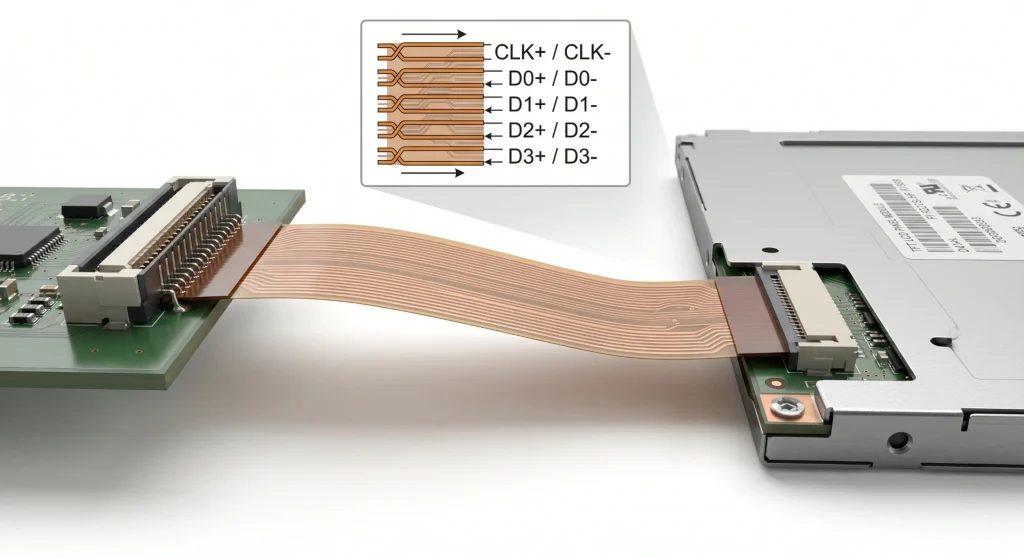
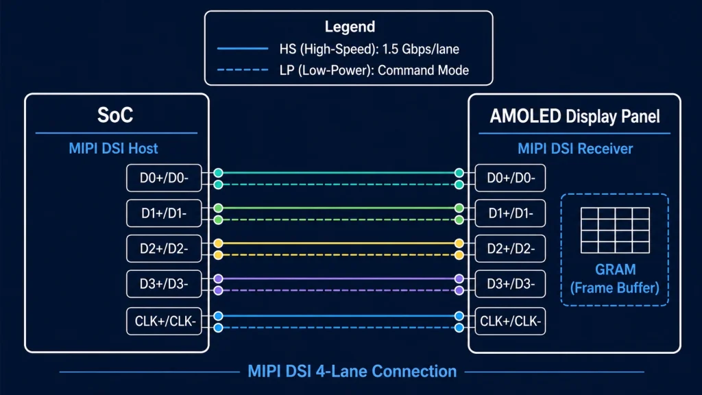
MIPI DSI (Display Serial Interface) was published by the MIPI Alliance in 2006, primarily aimed at solving the problem of connecting high-resolution displays to smartphone SoCs with minimal pin count and power consumption. The physical layer (D-PHY) uses differential pairs with a 200 mV voltage swing and supports per-lane data rates from 80 Mbps up to 2.5 Gbps in the D-PHY v2.1 specification — and up to 4.5 Gbps in C-PHY mode. A 4-lane MIPI DSI link at 1.5 Gbps per lane gives you 6 Gbps of raw throughput, which can feed a 1080p AMOLED at 90 Hz without issue.
The bus operates in two modes. High-Speed (HS) mode is used for pixel data streaming; LP (Low Power) mode is used for command transmission during panel initialisation and display mode changes. The DCS (Display Command Set) command layer sits above the physical and protocol layers and provides a standardised way to set brightness, rotation, tearing effect output, and other panel parameters without needing to know the specific panel IC details — assuming the panel is DCS-compliant, which most modern MIPI panels are.
Why MIPI Is Gaining Ground in Industrial
The answer is partly economics and partly silicon availability. MIPI DSI is now the default display interface on virtually every modern application processor targeting embedded Linux: NXP i.MX 8M Plus, Rockchip RK3568/RK3588, Qualcomm SA8155, STM32H747/H7Bx, Raspberry Pi 4/5 — all of them carry MIPI DSI host controllers as standard. Panel manufacturers have followed the silicon: the range of MIPI DSI LCD and AMOLED panels available in 4–10-inch sizes has expanded dramatically in the past five years, and prices have converged with equivalent RGB panels.
The pin count advantage is decisive for compact designs. A 2-lane MIPI DSI link for a 7-inch 1024×600 panel uses 6 signal pins (1 clock pair + 2 data pairs + 1 reset + 1 VSYNC). The equivalent RGB parallel bus needs 28. That difference matters a lot when you are routing a 4-layer PCB in a handheld device with a constrained form factor.
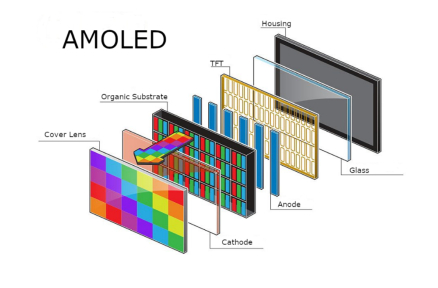
AMOLED panels with MIPI DSI and built-in GRAM (Graphics RAM) offer another advantage for battery-powered or intermittently-updated displays: Command Mode operation. The panel holds its own frame buffer, refreshes autonomously, and only needs new pixel data when the image changes. The host SoC can sleep between updates. In a typical industrial IoT field device showing sensor readings that change every few seconds, this can cut display subsystem power consumption by 60–80% compared to a Video Mode RGB panel that must be continuously fed pixel data at 60 fps.
Explore: Displays for Raspberry Pi — Kadi Display — MIPI DSI and HDMI display modules verified for Raspberry Pi 4 and Pi 5, with sizes from 3.5 to 10.1 inches and optional touch panels.
Also see: AMOLED Display Modules — Kadi Display — Compact AMOLED panels with MIPI DSI interface, suitable for wearables, industrial handhelds, and portable medical equipment.
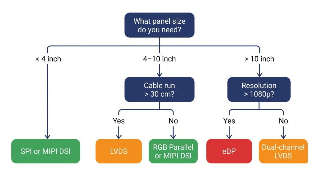
Practical Selection Guide: Matching Interface to Application
All three major industrial interfaces — RGB, LVDS, and MIPI DSI — are still actively designed into new products. The choice comes down to five factors: panel size, target resolution, cable run requirements, host processor support, and the operating environment. The table below maps common project scenarios to the right interface.
Interface Selection by Application Scenario
A Few Counter-Intuitive Cases Worth Knowing
LVDS for 7-inch panels? Yes, sometimes. If the display sits 30–50 cm from the compute board in a panel-mount enclosure and the factory environment has significant electrical noise (motor drives, switching supplies), LVDS’s superior noise immunity makes it worth the extra serialiser chip even at a size where RGB would technically work.
MIPI for industrial? Increasingly yes, especially on Cortex-A based platforms. If your SoC already has MIPI DSI hardware (most modern ones do), and the panel is within 20 cm of the board, MIPI DSI is often the cleanest solution: fewer PCB traces, lower EMI, and a growing catalogue of compatible panels.
RGB for new designs? It is harder to recommend as a first choice for designs started today if the processor supports MIPI DSI. But RGB is still the right answer when you need a specific panel that only comes in RGB flavour, or when your engineering team needs a fast bring-up on a platform with mature RGB driver support and no MIPI hardware.
The Other Interfaces — Brief Notes
SPI and Parallel (8080/6800)
SPI remains the default for small displays below 3.5 inches on microcontrollers without hardware display controllers (ESP32, Arduino, STM32G0/L4). Common panel ICs: ILI9341, ST7789, GC9A01. Bandwidth is limited — at 40 MHz SPI you get around 10–15 fps on a 320×240 display in 16-bit colour. For anything requiring smooth animation above 3 inches, SPI is inadequate. Parallel 8080 (8 or 16 bits) is the next step up, used on ESP32-S3 and similar MCUs for panels up to 800×480.
eDP (Embedded DisplayPort)
eDP is now the dominant interface for laptop panels and x86 embedded panel PCs. If you are designing a system based on an Intel NUC module, NVIDIA Jetson, or similar x86/x86-compatible platform, eDP is likely your display interface whether you chose it explicitly or not — it is what the module’s display output produces. Bandwidth is excellent (up to 8.1 Gbps per lane in eDP 1.4b, with 4 lanes available), and lane count scales gracefully from 1-lane for small panels to 4-lane for 4K displays.
HDMI and DisplayPort
These are consumer and professional AV interfaces, included here for completeness. In embedded industrial designs they appear when the display is a standard HDMI monitor rather than an integrated panel — think operator workstation monitors on factory floors, or large-format display signage driven from an embedded PC. They are not typically used for direct panel connection in custom hardware due to the electrical complexity (TMDS/HDCP for HDMI, AUX channel for DP) and the fact that integrated panels do not expose HDMI/DP inputs at the panel level.
VGA
Analog, legacy, and slowly disappearing. Worth a mention only because a non-trivial number of industrial maintenance projects still involve replacing or extending displays on equipment from the 2000s that outputs VGA. If you are doing that, a VGA-to-HDMI converter board is usually the simplest path rather than re-engineering the display interface.
Summary — Which Interface Should You Start With?
Here is the honest short version. If you are building an industrial product from scratch today with a modern application processor and a display in the 5–10-inch range, check whether your SoC has MIPI DSI hardware first. If it does, and your panel choice has a MIPI DSI version available, that is probably your path of least resistance. If the display is large (10 inches and above) or needs to sit more than 20–30 cm from the board, LVDS is your friend. RGB parallel is a solid fallback when your processor has LTDC or equivalent hardware and the panel runs at 800×480 or 1024×600.
And if you are still in the early stages of component selection — before you have committed to a processor or a panel — choosing the interface and then finding the silicon that supports it natively will save more engineering time than almost any other early decision.
Looking for panels across all these interface types? Browse Kadi Display’s full product catalogue — covering TFT LCD, AMOLED, high-brightness, bar-type, and custom display modules with RGB, LVDS, MIPI DSI, and SPI interfaces in sizes from 1.3 to 21 inches. OEM and ODM customisation available with short lead times from Shenzhen.
Need a custom interface adapter or a specific panel size not listed? Kadi Display’s engineering team handles ODM projects including custom FPC connector layouts, interface bridge IC integration, and wide-temperature panel qualification. Contact: Sales@sz-kadi.com
Disclaimer: All interface specifications referenced in this article are drawn from publicly available standards documents (ANSI/TIA-644, MIPI Alliance public specifications, JEDEC, and manufacturer datasheets). Brand names belong to their respective owners. Bandwidth figures are theoretical maximums; real-world throughput depends on implementation. This article does not constitute an endorsement of any specific product.
Leave A Comment

Latest Blog & News
- LCD Ribbon Cable Connector Guide: How to Specify ZIF, FFC/FPC, Pitch, and Contact Direction
- MIPI DSI Display Bring-Up Checklist: Eight Evidence Gates
- MIPI DSI LCD Platform Selection Guide: Match the Panel to the Host
- Common ZIF Connector Problems in Industrial Touchscreens and How to Fix Them
- ESP32-S3 RGB Display with GT911 and LVGL: A Practical Guide for Kiosk and HMI Applications