
How to Validate an Outdoor EV Charger Display for Sunlight and UV
2026-11-20
12:00
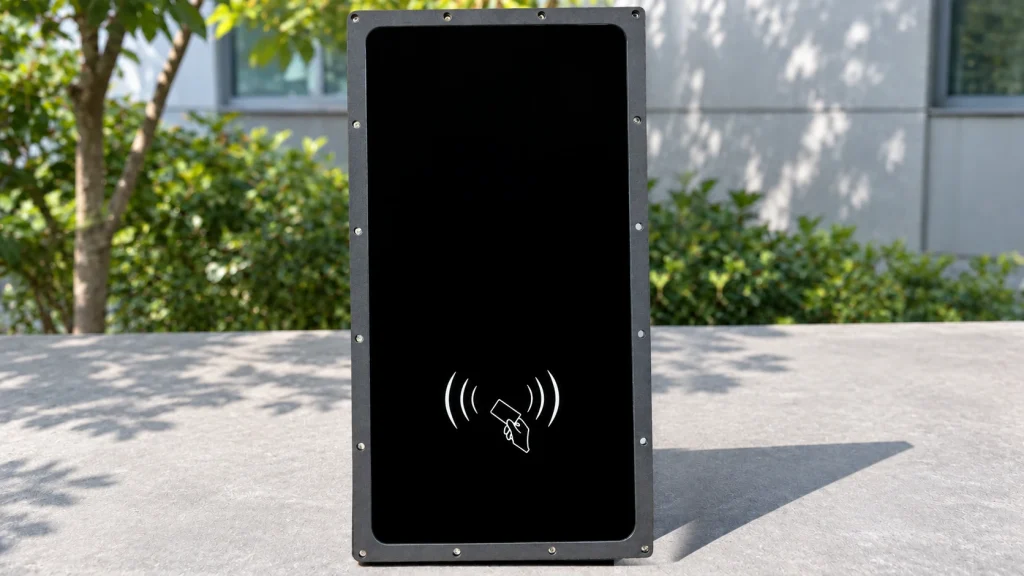
Validate an outdoor EV charger display by testing the complete viewing stack, its thermal behavior, and its installed connections under defined conditions. A brightness figure, UV-blocking material, and front-panel IP rating answer different questions. None replaces a powered evaluation of the assembled screen in the charger.
The practical task is to turn terms such as sunlight readable and UV resistant into observable acceptance criteria. This matters when a display looks clear on a bench but develops glare, touch problems, or optical changes after installation. The following approach separates those mechanisms and shows where material evidence can support a project decision.
Define the conditions before choosing acceptance limits
Describe where the charger will stand: fully exposed, shaded by a canopy, or facing a direction that receives afternoon sun. Record expected viewing positions, operating hours, ambient temperatures, cleaning practices, and whether rain can reach the front glass. Use the actual status and payment screens during evaluation.
A display used mainly under cover presents a different optical and thermal problem from the same display mounted in continuous direct sunlight. Establish what the user must read, from where, and under which lighting conditions. Then define a repeatable evaluation method and acceptable behavior.
General EV charger display selection considerations help narrow the component choices. Validation begins after that shortlist, when the assembled display must demonstrate suitability for the specific installation.
Check ambient readability through the finished front stack
Screen luminance measures emitted light. Outdoors, reflected light also affects the contrast a user sees. Cover glass, touch electrodes, polarizers, bonding interfaces, and surface treatments influence that result. A nominally brighter LCD can still present an objectionable reflection at the intended viewing angle.
Evaluate production-intent glass, touch, and bonding together. Check small text, charging status, warning colors, and low-contrast controls. Include different user heights and likely approach angles. Record the illumination and viewing geometry so later samples can be compared under similar conditions.
Optical bonding reduces internal reflective interfaces by filling the gap between layers. It does not remove the reflection at the outer surface. Kadi Display’s optical bonding versus air bonding guide explains the construction trade-offs; the validation decision should rest on the complete stack’s observed performance.
Avoid treating one nit threshold as proof of suitability for every charger. Brightness, reflectance, viewing angle, UI design, and installation geometry need to be considered together. Also check nighttime dimming so a daytime choice does not become uncomfortable after dark.
Separate UV blocking from resistance to aging
UV blocking describes how a material limits ultraviolet transmission under a stated measurement method. Resistance to aging concerns what happens to that material and the surrounding stack after exposure. An adhesive can block UV while other exposed layers, printed areas, or edges still require evaluation.
Ask for the measured wavelength range, sample construction, and measurement conditions behind a blocking percentage. Without those details, a percentage should not be interpreted as uniform protection across every ultraviolet wavelength or every component in the assembly.
The G6610 OCA selected for the charging project has material evaluation data reporting UV blocking above 99%. The same technical material includes accelerated exposure results on test specimens. Those results support material assessment; they are not a report that the finished charger display passed the same exposures.
During assembly evaluation, inspect yellowing, haze, bubbles, edge lift, delamination, and image uniformity. Define the observation conditions and permitted change before testing. A photograph with no reference lighting or baseline can miss gradual optical deterioration.
Read accelerated exposure reports in their test context
An exposure duration becomes useful only with the test method and conditions. Review the light source, filters, irradiance, temperature controls, humidity or moisture cycle, specimen construction, and measured changes. Different setups can stress materials differently, even when the exposure hours are identical.
For example, the G6610 material evaluation includes a 1,008-hour xenon exposure sequence using test specimens. That duration must stay attached to the material sample and reported conditions. It should not be converted into a number of outdoor service years for a display assembly.
Agree how the selected production stack will be evaluated after material screening. Include the cover, ink, adhesive, polarizer interfaces, edge treatment, and mounting conditions relevant to the design. Preserve baseline measurements and inspect the same features after exposure and recovery.
Evaluate solar heating and touch while powered
UV protection does not resolve heat absorbed under sunlight. A sealed charger can expose the display to temperatures above the surrounding air, while a high-brightness backlight adds internal heat. The relevant temperatures depend on enclosure color, orientation, thermal paths, and operating load.
Measure temperatures at the locations required by the selected component specifications. Check the image and touch behavior during the hot condition, not only after cooling. Look for reduced readability, temporary image changes, touch errors, or unexpected resets. Verify startup and recovery at the required low-temperature conditions as well.
Capacitive touch also needs application testing with the intended cover, grounding, firmware, and charger electronics. If wet operation or gloves are required, specify and evaluate those conditions explicitly. A 10-point touch specification alone does not establish either capability.
Check sealing and the harness in the installed assembly
A front-panel IP65 scope concerns the defined front boundary. It does not automatically protect the rear PCB, cable entry, or connector. Preserve the mounting and sealing arrangement associated with that scope, then verify the finished charger’s own enclosure requirements.
Cable routing can affect that arrangement. A stiff bend may load a connector, interfere with a gasket, or prevent the service door from closing correctly. Check these details with the production-intent harness installed, including its retention hardware and service loop.
Combining LVDS, backlight, I2C, and power into one harness simplifies connection handling, but all functions still need powered checks. Exercise touch while changing brightness and running representative charger functions. Treat ingress, optical performance, and electrical stability as related acceptance activities with distinct pass criteria.
Apply the evidence to the 10.1 inch project
Kadi Display’s confirmed outdoor charging configuration used a 10.1-inch, 1280 × 800 display with 850 cd/m² typical brightness, 10-point capacitive touch, an IK08 specification, and -20°C to +70°C operation. The optical stack used G6610 OCA, and IP65 applied to the front panel.
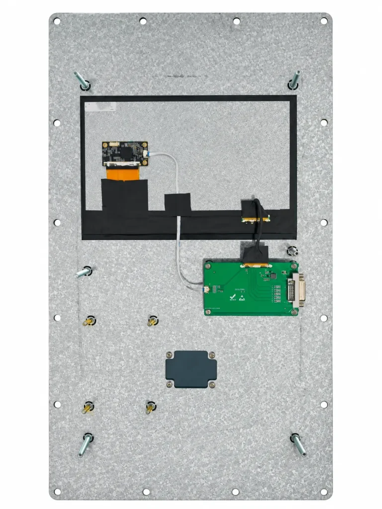
The project also packaged three original cable groups into one harness. Its DVI connector has project-specific pin assignments and should not be treated as an ordinary DVI video interface. These details define a real implementation, not a universal recipe for every climate or host platform.
For another installation, Kadi Display’s custom display services provide a starting point for reviewing brightness, touch, bonding, cable integration, and housing together. The approval package should identify the exact configuration, applicable test evidence, unresolved conditions, and agreed acceptance limits. Material data should remain distinguishable from finished-assembly results.
Schlussfolgerung
Outdoor display validation works when each claim has a defined scope and a matching evaluation. Check readability through the finished stack, interpret UV evidence at the correct material or assembly level, and test powered thermal and touch behavior with the installed harness. Preserve the front-panel boundary when discussing IP65.
Frequently asked questions
Is 850 cd per square meter sufficient for an outdoor charger?
It depends on reflections, viewing geometry, lighting, and UI requirements. This project’s typical luminance is a configuration fact; suitability for another installation requires evaluation.
Does UV blocking above 99 percent prove the display lifetime?
No. It is material evidence under its measurement conditions. It does not establish the service life of the complete display or charger.
Does optical bonding make the screen waterproof?
Bonding fills an optical interface. Enclosure sealing and the defined ingress-protection boundary need separate design and verification.
Can the single harness replace outdoor testing?
No. It changes connection packaging. Readability, aging, temperature, touch, and enclosure behavior still require application-specific checks.
For a project-specific validation discussion, contact the technical team at Kadi Display with the installation environment, host details, front-stack drawing, cable route, and required acceptance conditions.
Hinterlasse einen Kommentar

Neueste Blog & Nachrichten
- How to Validate an Outdoor EV Charger Display for Sunlight and UV
- EV Charger Display Integration With One Custom Cable Harness
- What to Ask an Industrial Display Manufacturer Before Design-In: Lifecycle, EOL, and Customization
- LCD Display Module vs Custom Display Assembly: What Does an OEM Actually Need?
- Industrial Display Obsolescence Management Plan Template: BOM, PCN, EOL, LTB, and Validation