




Inicio
-
Blog & Noticias
-
De la placa de demostración al producto industrial: Cómo lograr que las pantallas táctiles GT911 + LVGL sean estables para un funcionamiento continuo (24/7)
De la placa de demostración al producto industrial: Cómo lograr que las pantallas táctiles GT911 + LVGL sean estables para un funcionamiento continuo (24/7)
2026-05-29
11:19
De la placa de demostración al producto industrial: Cómo lograr que las pantallas táctiles GT911 + LVGL sean estables para un funcionamiento continuo (24/7)
Guía de ingeniería de hardware y firmware para el endurecimiento contra la compatibilidad electromagnética (EMC), la gestión térmica, la validación de rodaje, la consistencia táctil y el mantenimiento a largo plazo del firmware para pantallas HMI de grado de producción.
Por el equipo técnico de Kadi Display | www.kadidisplay.com
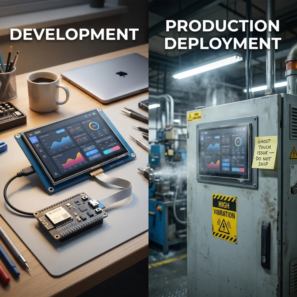
La brecha que perjudica a los productos: demostración frente a producción.
La mayoría de los proyectos de pantallas integradas siguen el mismo patrón. Un ingeniero ensambla un kit de desarrollo (una placa ESP32-S3, un panel IPS de 7 pulgadas con pantalla táctil GT911 y la biblioteca gráfica LVGL) y, en una semana, tiene una demostración realmente impresionante. La interfaz de usuario es fluida, la respuesta táctil es rápida y los colores son vívidos. El proyecto avanza.
Luego, las primeras unidades de preproducción llegan a la fábrica. O el primer despliegue piloto se realiza en una planta procesadora de alimentos. O cien unidades se distribuyen a una flota de vehículos que opera en el norte de Canadá. En cuestión de semanas, comienzan a llegar los informes de fallas: toques fantasma al encender el dispositivo, pantallas que se congelan después de 72 horas de funcionamiento continuo, pantallas táctiles que funcionan perfectamente a temperatura ambiente pero se vuelven erráticas a -10 °C. Nada de esto apareció durante el desarrollo de la demo.
La diferencia entre una demostración funcional y una pantalla táctil industrial fiable que funcione las 24 horas del día, los 7 días de la semana, no es un fallo de software. Es un conjunto de disciplinas de ingeniería que el desarrollo de demostraciones simplemente no abarca: inmunidad EMC, gestión térmica en todo el rango de funcionamiento, comportamiento de envejecimiento de los componentes, consistencia táctil entre lotes de produccióny Mantenimiento del firmware sin acceso físicoCada uno de ellos tiene modos de fallo específicos, soluciones específicas y pruebas de validación específicas. Esta guía abarca los cinco.
Refuerzo de la compatibilidad electromagnética (EMC): deteniendo las interferencias antes de que lleguen al GT911.
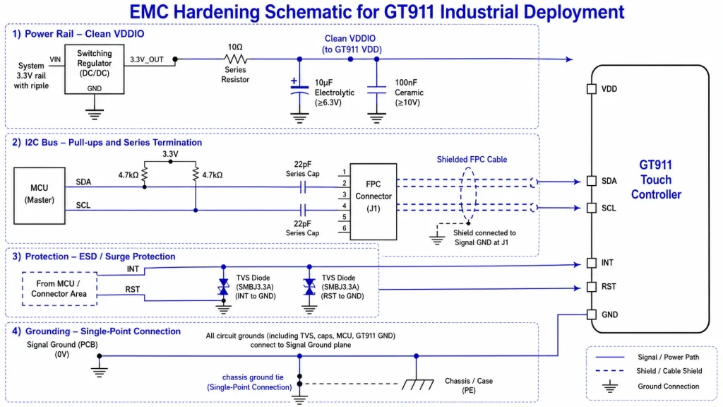
El controlador táctil GT911 funciona midiendo cambios de capacitancia extremadamente pequeños —normalmente entre 0,1 y 1 pF— en la matriz de electrodos táctiles. Cualquier interferencia eléctrica que se acople a la película táctil o a las líneas de comunicación I²C produce ruido que el controlador interpreta como eventos táctiles erróneos. En un laboratorio con una placa de desarrollo alimentada por USB, esto rara vez supone un problema. En un entorno industrial con variadores de motor, solenoides, iluminación fluorescente y fuentes de alimentación conmutadas cercanas, es el principal modo de fallo.
Las cuatro vías de acoplamiento de interferencia
Comprender por dónde ingresa la interferencia al sistema es un requisito previo para detenerla. Cuatro vías de acoplamiento son relevantes para las pantallas táctiles industriales basadas en GT911:
Filtrado de rieles de potencia: las cifras que importan
El GT911 consume aproximadamente entre 30 y 80 mA de su fuente de alimentación VDD durante el escaneo activo. La tensión de alimentación debe mantenerse dentro de un margen de ±5 % del valor nominal (normalmente 2,8 V o 3,3 V) en todas las condiciones de carga, incluyendo la corriente de arranque en frío. En sistemas industriales con líneas de alimentación compartidas, se requiere un filtro local directamente en los pines de alimentación del GT911.
Topología de filtro recomendada: una resistencia de 10 Ω en serie con la fuente de alimentación, seguida de un condensador electrolítico de 10 µF y un condensador cerámico de 100 nF a tierra, ubicados a menos de 5 mm de los pines AVDD y VDDIO del GT911. Esto crea un filtro paso bajo con una atenuación de -3 dB a aproximadamente 1,6 kHz, atenuando la ondulación del regulador de conmutación (típicamente de 100 a 500 kHz) en más de 40 dB. Mida la ondulación en los pines de alimentación del GT911 con un osciloscopio de 200 MHz de ancho de banda después del filtrado; el objetivo es que sea inferior a ±50 mV pico a pico bajo carga operativa completa.
Refuerzo del bus I²C
El bus I²C transmite datos táctiles a 400 kHz (modo rápido) entre el GT911 y el procesador principal. A esta frecuencia, los tramos de cable de más de 100 mm comienzan a actuar como antenas que captan interferencias radiadas. Tres prácticas previenen fallos de comunicación I²C en hardware de producción:
- Mantenga la longitud del cable I²C por debajo de 150 mm. Siempre que sea posible, si el panel debe separarse físicamente de la placa de circuito impreso principal, utilice un cable de par trenzado apantallado con el apantallamiento conectado a tierra en un solo extremo.
- Agregar 4.7 kΩ resistencias pull-up a SDA y SCL en el extremo del host. Las resistencias pull-up demasiado débiles (>10 kΩ a una velocidad de bus de 400 kHz) producen flancos ascendentes lentos que parecen errores de datos cuando hay ruido presente.
- Coloque condensadores de terminación en serie de 22 pF. en SDA y SCL en el conector de borde de la PCB principal. Esto reduce la velocidad de los bordes lo suficiente como para disminuir las emisiones radiadas sin afectar el cumplimiento de la temporización I²C, una técnica comúnmente utilizada en diseños certificados IEC 61000-4-4.
La norma IEC 61000-4-4 (inmunidad a transitorios eléctricos rápidos/ráfagas) es la que se utiliza para probar la mayoría de los equipos de visualización industriales para obtener el marcado CE. Las pruebas consisten en aplicar transitorios de ráfaga de 2 kV a las líneas de alimentación y de E/S. Los diseños que superan esta prueba sin errores de comunicación GT911 con el método de filtrado descrito anteriormente suelen superar también las normas IEC 61000-4-2 (ESD) de nivel 3 e IEC 61000-4-6 (inmunidad conducida) de nivel 3, las tres normas más relevantes para los equipos HMI industriales.
Gestión térmica: funcionamiento en todo el rango de temperaturas.
El conjunto LVGL + GT911 que funciona en una pantalla táctil industrial 24/7 genera tres fuentes de calor distintas que deben gestionarse: la matriz de LED de retroiluminación (la principal), el procesador principal (significativo durante el renderizado intensivo de LVGL) y el circuito de escaneo del controlador táctil (menor, normalmente < 200 mW). En una carcasa industrial sellada, las tres fuentes deben conducirse a las paredes de la carcasa; la convección no es una opción.
Carga térmica de la retroiluminación
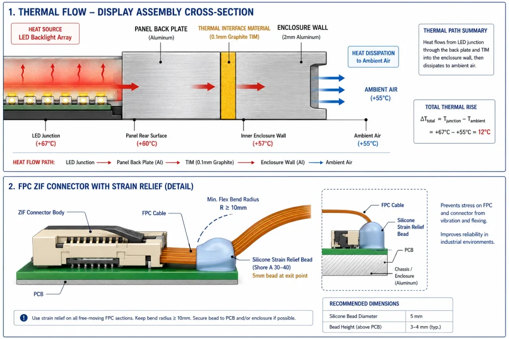
Un panel IPS de 7 pulgadas con un brillo de retroiluminación de 800 nits disipa típicamente entre 8 y 14 W desde la matriz de LED. Este calor debe viajar desde las tiras de LED en el borde del panel, a través de la placa posterior del panel, a través de un material de interfaz térmica (TIM), hasta la carcasa. El aumento de temperatura desde la temperatura ambiente hasta la unión del LED está determinado por:
ΔT = P × (R_TIM + Recinto R)
Donde P es la potencia de la retroiluminación (W), R_TIM es la resistencia térmica de la capa TIM (°C/W) y R_enclosure es la resistencia térmica de la pared interior de la carcasa al aire ambiente (°C/W). Con una capa TIM de grafito de 0,1 mm (R_TIM ≈ 0,05 °C/W por cm²) y una pared de carcasa de aluminio de 2 mm (R_enclosure ≈ 1,2 °C/W para un panel de 150 × 100 mm), una retroiluminación de 10 W produce un aumento de la temperatura de la unión de aproximadamente 12 °C por encima de la temperatura ambiente. A +55 °C ambiente (una temperatura común de los paneles exteriores), la temperatura de la unión del LED alcanza ~67 °C, muy por debajo de la clasificación de 85 °C de los LED de retroiluminación de calidad, pero dejando solo 18 °C de margen para la variación de producción.
La regla práctica de diseño: Especificar la atenuación adaptativa y la potencia de la retroiluminación objetivo a un máximo del 60 % de la potencia máxima nominal durante el funcionamiento continuo.Esto mantiene la temperatura de la unión por debajo de 65 °C a una temperatura ambiente de +55 °C con la resistencia térmica típica de la carcasa, lo que proporciona un margen de vida útil adecuado. Los sistemas basados en LVGL implementan esto mediante un sensor de luz ambiental (ALS) que alimenta el controlador PWM de la retroiluminación, como se explica en la sección de firmware.
Comportamiento en arranque en frío y respuesta fluida de la pantalla LCD
El fluido de cristal líquido en los paneles TFT-LCD presenta una viscosidad que aumenta bruscamente por debajo de 0 °C. Un panel LCD estándar encendido a -10 °C mostrará una respuesta de píxeles lenta: la pantalla está técnicamente encendida, pero el movimiento parece como si el panel funcionara a 10-15 fps, incluso cuando el búfer de fotogramas se actualiza a 60 Hz. Esta es una propiedad del material del fluido de cristal líquido, no un problema de firmware, y es imperceptible durante el desarrollo de demostraciones realizado a temperatura ambiente.
Para implementaciones que incluyen escenarios de arranque en frío (quioscos exteriores, pantallas montadas en vehículos, terminales de almacén en instalaciones refrigeradas), se pueden aplicar dos enfoques:
- Especificación del panel de amplio rango de temperaturaLos paneles IPS con formulaciones de fluido LC extendidas mantienen un tiempo de respuesta de ≥5 ms hasta −20 °C. Estos paneles tienen especificaciones diferentes a las de los paneles IPS comerciales estándar; verifique explícitamente la especificación del tiempo de respuesta a baja temperatura con su proveedor de paneles.
- Película calefactora detrás de la pantalla LCDUn elemento calefactor resistivo, adherido a la cara posterior del panel y controlado por un termistor, mantiene la temperatura del panel por encima del umbral mínimo de funcionamiento en condiciones ambientales frías. La potencia típica del calentador es de 5 a 10 W; se activa por debajo de +5 °C y se desactiva por encima de +15 °C. El calentador debe alimentarse de la misma fuente de alimentación regulada que el panel para evitar que las fluctuaciones de voltaje durante su activación interfieran con la calibración del GT911.
Ciclos térmicos y fiabilidad del conector FPC
Los ciclos de temperatura —el ciclo diario que va desde la temperatura ambiente fría durante la noche hasta la temperatura de funcionamiento cálida— generan tensión mecánica en los conectores FPC (cable plano impreso) entre la película táctil y la PCB. La diferencia en el coeficiente de dilatación térmica (CTE) entre el sustrato FR4 de la PCB (CTE ≈ 17 ppm/°C) y el FPC de poliimida (CTE ≈ 20 ppm/°C) produce un movimiento relativo de aproximadamente 0,03 mm por centímetro de longitud de cable por cada cambio de temperatura de 50 °C. Tras miles de ciclos, esto somete a tensión los contactos del conector ZIF (fuerza de inserción cero).
Mitigación de producción: aplique un cordón de alivio de tensión con adhesivo de silicona de baja dureza (Shore A 30–40) en el punto donde el FPC sale del cuerpo del conector ZIF. Este paso de producción, que solo toma 5 minutos, reduce drásticamente las fallas en campo relacionadas con el FPC en implementaciones con ciclos térmicos. Inspeccione esta unión como parte de su proceso de control de calidad de entrada para los módulos de pantalla ensamblados.
Pruebas de rodaje y validación mediante envejecimiento acelerado
Enviar el primer lote de producción sin realizar pruebas de rodaje es el error más común en el desarrollo de interfaces hombre-máquina (HMI) industriales. Las fallas de los componentes siguen la conocida curva de la bañera: la tasa de fallas es elevada durante el período inicial (mortalidad infantil), disminuye hasta alcanzar una tasa baja y estable durante la vida útil y luego vuelve a aumentar a medida que los componentes se desgastan. Una prueba de rodaje de 24 horas a temperatura elevada permite detectar las fallas de mortalidad infantil antes de que el producto llegue al cliente.
Protocolo de rodaje para sistemas GT911 + LVGL
Un protocolo de rodaje de producción para una pantalla táctil industrial que funcione las 24 horas del día, los 7 días de la semana, debe poner a prueba todos los modos de fallo que afectan a la mortalidad infantil:
� Industria Línea base: qué detecta la prueba de rodaje de 24 horas.
Los datos de campo de los fabricantes de pantallas integradas indican que las pruebas de envejecimiento acelerado a +65 °C durante 24 horas detectan aproximadamente el 68 % de los fallos iniciales que, de otro modo, aparecerían en las primeras 500 horas de funcionamiento. Los modos de fallo más comunes detectados son: soldadura fría en el controlador táctil (23 % de los fallos detectados), contacto intermitente del conector FPC (31 %), inestabilidad del controlador de retroiluminación bajo carga térmica (18 %), bloqueo de la dirección I²C del GT911 en un circuito de reinicio marginal (15 %) y bucle de reinicio del temporizador de vigilancia LVGL por fallo de asignación de memoria (13 %).
Los datos de campo de los fabricantes de pantallas integradas indican que las pruebas de envejecimiento acelerado a +65 °C durante 24 horas detectan aproximadamente el 68 % de los fallos iniciales que, de otro modo, aparecerían en las primeras 500 horas de funcionamiento. Los modos de fallo más comunes detectados son: soldadura fría en el controlador táctil (23 % de los fallos detectados), contacto intermitente del conector FPC (31 %), inestabilidad del controlador de retroiluminación bajo carga térmica (18 %), bloqueo de la dirección I²C del GT911 en un circuito de reinicio marginal (15 %) y bucle de reinicio del temporizador de vigilancia LVGL por fallo de asignación de memoria (13 %).
Validación automatizada de la precisión táctil
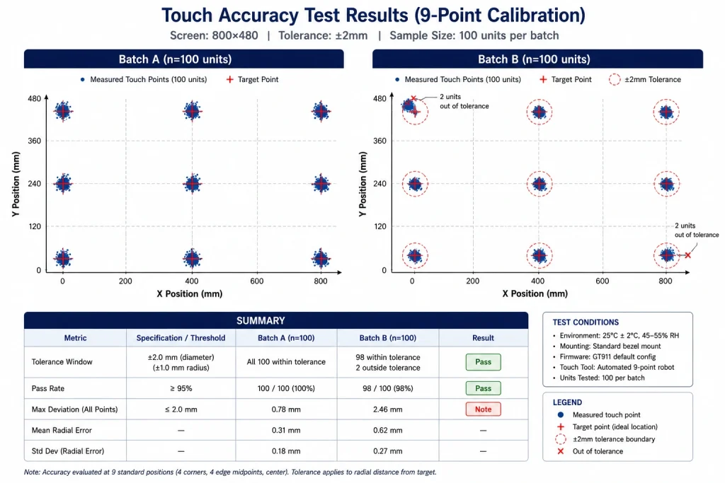
Las pruebas táctiles humanas durante el rodaje son poco prácticas e inconsistentes. La validación táctil a escala de producción requiere un dispositivo de prueba, un soporte que dirige un lápiz conductor (o un conjunto de lápices) a coordenadas conocidas en la superficie de la pantalla táctil bajo una fuerza controlada (normalmente de 150 a 250 gf según la norma IEC 60068-2-75 equivalente), lee la coordenada informada por el firmware del host y registra el error.
Matriz de prueba mínima para la validación táctil del GT911 PCAP: las cuatro esquinas del área activa, los cuatro puntos medios de los bordes y el centro (nueve puntos en total). En cada punto, se miden 20 eventos táctiles y se calcula el error absoluto medio y la desviación estándar. Especificación de producción aceptable para HMI industrial: error medio < 2 mm, desviación estándar < 0,8 mmEn los nueve puntos, tanto a +25 °C como a +65 °C. Cualquier unidad que no supere estos umbrales indica un problema de registro de la película táctil que se puede corregir mediante la recalibración a través del registro de configuración GT911 0x8047–0x80FF, pero solo si el conjunto mecánico subyacente es aceptable.
Consistencia táctil entre lotes de producción
Una calibración táctil GT911 que funciona a la perfección en el primer lote de producción podría requerir ajustes en el segundo lote si el proveedor entrega paneles con un grosor de película táctil o una constante dieléctrica ligeramente diferentes. Esto no constituye un fallo de calidad —es una variación normal dentro de las especificaciones del componente—, pero requiere una validación de la calibración durante la inspección de calidad de entrada, un paso que muchos equipos omiten.
Registros de configuración del GT911: ¿Qué cambia entre lotes?
El bloque de configuración de 186 bytes del GT911 (registros 0x8047–0x80FF) contiene parámetros que definen cómo el controlador interpreta las mediciones de capacitancia sin procesar como eventos táctiles. Tres registros explican la mayor parte de la variación en el comportamiento táctil entre lotes:
Implementación de un paso de verificación de configuración en las TIC
La prueba en circuito (ICT) o prueba funcional al final de la línea de ensamblaje de PCB es el lugar idóneo para validar la configuración del GT911. La secuencia de prueba consiste en: encender la placa, leer el bloque de configuración completo del GT911 a través de I²C, compararlo con la configuración de referencia almacenada en el sistema de prueba, detectar cualquier desviación y, opcionalmente, escribir el bloque de configuración corregido y la suma de comprobación verificada antes de que la unidad pase al ensamblaje final.
Arquitectura de vigilancia de firmware para funcionamiento continuo (24/7)
Una pantalla táctil que funciona correctamente durante 23 horas y 59 minutos, pero que requiere reiniciarse a las 24 horas, no es una pantalla industrial de funcionamiento continuo (24/7); es simplemente un dispositivo que permanece encendido de forma permanente. El firmware debe diseñarse específicamente para un funcionamiento indefinido sin supervisión, lo que implica considerar cada componente de software como una posible fuente de fallos y diseñar mecanismos de recuperación para cada uno.
La jerarquía de vigilancia de tres niveles
El firmware integrado robusto, que funciona las 24 horas del día, los 7 días de la semana, utiliza una arquitectura de vigilancia por capas en lugar de un único temporizador de vigilancia de hardware:
Recuperación del I²C GT911: Manejo del bloqueo del bus
Uno de los problemas de fiabilidad más persistentes en las implementaciones de GT911, que no se presentan las 24 horas del día, los 7 días de la semana, es el bloqueo del bus I²C: una situación en la que una interrupción transitoria de la alimentación o una descarga electrostática (ESD) deja al GT911 en medio de una transmisión, manteniendo el SDA en estado bajo e impidiendo cualquier comunicación I²C posterior. El sistema de vigilancia de hardware no puede detectar esta condición porque el firmware se está ejecutando normalmente; simplemente se queda bloqueado esperando la comunicación I²C.
La secuencia de recuperación debe implementarse en software y activarse mediante errores de tiempo de espera de I²C:
⚠ Pista Eventos de recuperación en el registro no volátil
Cada evento de recuperación automática (reinicio del bus I²C, reinicio del temporizador de vigilancia LVGL, WDT de hardware) debe registrarse en NVS (almacenamiento no volátil) con una marca de tiempo y un código de evento. Cuando se devuelve una unidad de campo para su análisis, este registro revela si el hardware presenta fallos intermitentes o un fallo sistemático. Sin este registro, el análisis de la causa raíz de los problemas de fiabilidad 24/7 se convierte en una mera conjetura.
Cada evento de recuperación automática (reinicio del bus I²C, reinicio del temporizador de vigilancia LVGL, WDT de hardware) debe registrarse en NVS (almacenamiento no volátil) con una marca de tiempo y un código de evento. Cuando se devuelve una unidad de campo para su análisis, este registro revela si el hardware presenta fallos intermitentes o un fallo sistemático. Sin este registro, el análisis de la causa raíz de los problemas de fiabilidad 24/7 se convierte en una mera conjetura.
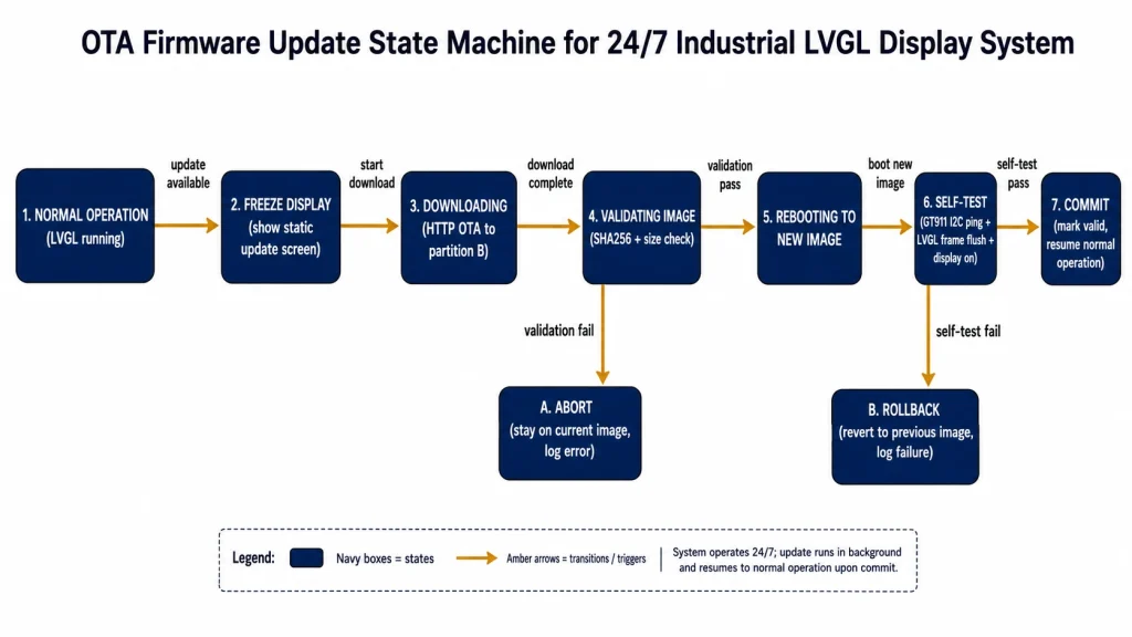
Actualizaciones de firmware OTA: mantenimiento de sistemas operativos las 24 horas del día, los 7 días de la semana.
Una pantalla táctil industrial que funciona las 24 horas del día, los 7 días de la semana, y que requiere acceso físico para las actualizaciones de firmware, representa un problema operativo a gran escala. Las unidades desplegadas en instalaciones remotas, flotas de vehículos o redes de quioscos no tripulados necesitan un mecanismo de actualización OTA (inalámbrico) fiable que mantenga la disponibilidad ininterrumpida durante todo el proceso de actualización.
Actualización OTA segura para sistemas de visualización LVGL
El mecanismo de actualización OTA de ESP-IDF escribe la nueva imagen de firmware en una partición OTA secundaria mientras la imagen actual continúa ejecutándose, y luego valida la nueva imagen antes de confirmarla. Esto proporciona actualizaciones atómicas: si la nueva imagen no arranca, el gestor de arranque revierte automáticamente a la versión anterior. Para sistemas de visualización, se aplican consideraciones adicionales:
- Congelar la pantalla durante la descarga OTA — La renderización de LVGL durante una descarga HTTP OTA compite por el ancho de banda de la PSRAM con el DMA de descarga. Mostrar una pantalla estática de "Actualización en curso" (una sola etiqueta lv_label sobre fondo sólido) reduce el tráfico de PSRAM de LVGL a casi cero y elimina la principal causa de corrupción en las descargas OTA en sistemas equipados con pantalla.
- Valida la pantalla y la función táctil antes de confirmar. — después de que la nueva imagen arranque por primera vez, ejecute una secuencia de autodiagnóstico antes de llamar esp_ota_mark_app_valid_cancel_rollback()La autocomprobación debería confirmar: comunicación I²C con GT911 (lectura del registro de ID de producto 0x8140), finalización del vaciado de trama RGB en 200 ms y ejecución de LVGL lv_timer_handler() sin fallos.
- Actualizaciones programadas durante ventanas de baja actividad — El sistema de monitorización adaptativa de brillo y actividad de LVGL puede identificar periodos sin interacción táctil (normalmente durante la noche). Las descargas OTA iniciadas durante estos periodos evitan interrumpir a los operadores que estén trabajando.
Gestión de firmware y configuración del GT911
Los registros de configuración del GT911 se almacenan en la memoria interna tipo OTP del controlador y se conservan incluso después de apagar y encender el dispositivo. Cuando una actualización de firmware modifica la interfaz de usuario de LVGL de forma que altere los requisitos de sensibilidad táctil (por ejemplo, añadiendo objetivos táctiles más pequeños que requieren una mayor sensibilidad del GT911), la configuración del GT911 debe actualizarse como parte de la actualización del firmware de la aplicación.
Buenas prácticas: almacene el bloque de configuración del GT911 de destino en la imagen del firmware del ESP32 como una matriz constante. En cada arranque, tras la inicialización del GT911, lea la configuración actual, compare la suma de comprobación con la de la configuración de destino y, si difieren, escriba la configuración de destino y reinicie el GT911. Esto garantiza que la configuración del GT911 se mantenga sincronizada con la versión del firmware durante las actualizaciones OTA sin necesidad de actualizar el firmware del GT911 por separado.
Selección de un proveedor de paneles para compromisos de producción 24/7
Las decisiones de diseño del hardware —en concreto, la combinación de módulo de pantalla y panel táctil que se especifica— determinan el nivel máximo de fiabilidad que puede alcanzar el firmware. Un panel que experimente una degradación prematura de la retroiluminación, una calibración GT911 inconsistente de fábrica o problemas de calidad en el conector FPC generará fallos en el campo que ningún sistema de supervisión del firmware ni actualización OTA podrá solucionar.
Criterios clave de calificación de proveedores para el suministro de pantallas industriales 24/7:
Kadi Display’ s Módulos de pantalla táctil TFT-LCD industriales Incluye configuraciones con controladores GT911 calibrados de fábrica, tecnología de panel IPS con amplios ángulos de visión y funcionamiento en un amplio rango de temperaturas. Para los equipos de diseño de productos que evalúan la estética del panel junto con la fiabilidad, su guía sobre Diseño de cristal protector personalizado y pantalla táctil industrial Cubre el alcance completo de las opciones de personalización del vidrio de la carcasa para implementaciones HMI industriales de marca. La selección de tecnología de panel se cubre en profundidad en su Guía comparativa TN vs IPS vs VA — Contexto relevante para los equipos que deben decidir entre diferentes tipos de paneles para entornos de visualización 24/7.
Lista de verificación de preparación para la producción
Revisión estructurada de las fases previa al primer envío de producción. Cada elemento representa una deficiencia que ha provocado fallos reales en implementaciones de HMI industriales:
Soporte técnico y referencia de productos
Para módulos de pantalla táctil TFT-LCD de grado industrial con tecnología táctil GT911 calibrada de fábrica, panel IPS, funcionamiento en amplio rango de temperatura y compromisos de continuidad de suministro adecuados para implementaciones industriales 24/7, póngase en contacto con Kadi Display en Sales@sz-kadi.comDisponemos de servicios OEM y ODM, que incluyen vidrio de cubierta personalizado, unión óptica y especificaciones de paneles para un amplio rango de temperatura. Ver módulos de pantalla táctil TFT industriales →
Para módulos de pantalla táctil TFT-LCD de grado industrial con tecnología táctil GT911 calibrada de fábrica, panel IPS, funcionamiento en amplio rango de temperatura y compromisos de continuidad de suministro adecuados para implementaciones industriales 24/7, póngase en contacto con Kadi Display en Sales@sz-kadi.comDisponemos de servicios OEM y ODM, que incluyen vidrio de cubierta personalizado, unión óptica y especificaciones de paneles para un amplio rango de temperatura. Ver módulos de pantalla táctil TFT industriales →
Descargo de responsabilidad: Los ejemplos de código y los datos de tasa de fallos de esta guía tienen fines didácticos y se basan en la experiencia general del sector. Los valores específicos (tiempos de espera del temporizador de vigilancia, valores de los componentes del filtro, umbrales de temperatura) deben validarse para cada entorno de implementación y configuración de hardware. Se incluyen referencias a las normas IEC a modo informativo; las pruebas de conformidad deben ser realizadas por un laboratorio de ensayos acreditado. GT911 es una marca comercial de Shenzhen. Goodix Technology Co., Ltd. ESP32-S3 es una marca registrada de Espressif Sistemas. LVGL es un proyecto de código abierto bajo licencia MIT. Todas las demás marcas pertenecen a sus respectivos propietarios.
PREVIOR
Cómo conectar un panel táctil capacitivo GT911 a LVGL en ESP32-S3
Siguiente
Pantallas Raspberry Pi para HMI industriales
Deja un comentario

Últimos blogs y noticias
- Industrial LCD EOL: What Happens from Pre-Announcement to Replacement Mass Production?
- Electronic Component Obsolescence Management for Industrial Displays: An OEM Guide
- How to Develop a Production Ready Custom Display Assembly TFT Module Touch Cover Glass FPC Bonding and Mounting
- 15 Pin vs 22 Pin Raspberry Pi DSI Connectors Cable Pinout and Compatibility
- Native MIPI DSI vs LVDS or HDMI Bridge: An OEM Display Architecture Decision Guide

