




Casa
-
Blog & Novas
-
Da placa de demonstração ao produto industrial: tornando as telas sensíveis ao toque GT911 + LVGL estáveis para operação 24 horas por dia, 7 dias por semana.
Da placa de demonstração ao produto industrial: tornando as telas sensíveis ao toque GT911 + LVGL estáveis para operação 24 horas por dia, 7 dias por semana.
2026-05-29
11:19
Da placa de demonstração ao produto industrial: tornando as telas sensíveis ao toque GT911 + LVGL estáveis para operação 24 horas por dia, 7 dias por semana.
Um guia de engenharia de hardware e firmware para proteção EMC, gerenciamento térmico, validação de burn-in, consistência de toque e manutenção de firmware a longo prazo para displays HMI de nível de produção.
Por Equipe Técnica da Kadi Display | www.kadidisplay.com
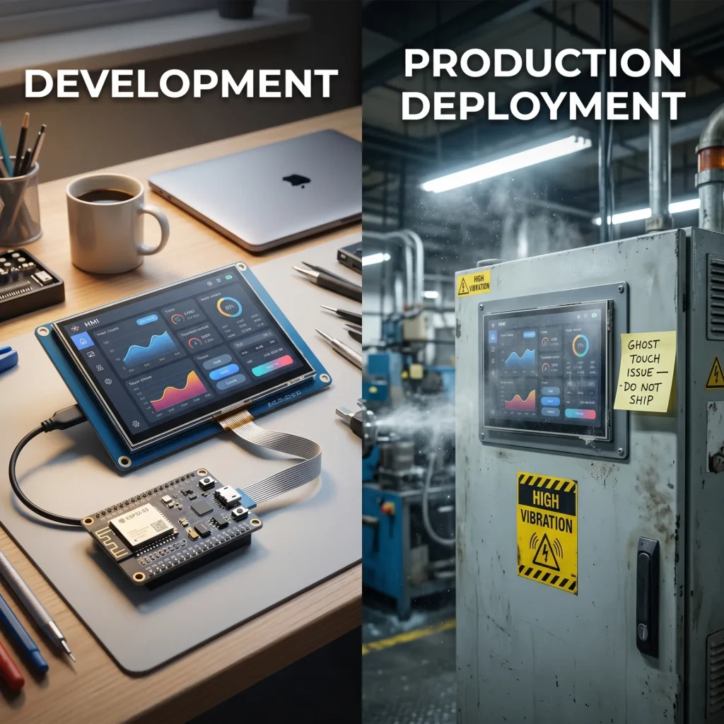
A lacuna que prejudica os produtos — Demonstração vs. Produção
A maioria dos projetos de displays embarcados segue a mesma trajetória. Um engenheiro monta um kit de desenvolvimento — uma placa ESP32-S3, um painel IPS de 7 polegadas com touchscreen GT911 e a biblioteca gráfica LVGL — e, em uma semana, tem uma demonstração realmente impressionante. A interface do usuário é fluida, a resposta ao toque é rápida e as cores são vibrantes. O projeto avança.
Então, as primeiras unidades de pré-produção chegam à fábrica. Ou a primeira unidade piloto é instalada em uma fábrica de processamento de alimentos. Ou cem unidades são enviadas para uma frota de veículos que opera no norte do Canadá. Em poucas semanas, começam a chegar os relatórios de falhas: toques fantasmas na inicialização, telas que congelam após 72 horas de operação contínua, toque que funciona perfeitamente em temperatura ambiente, mas se torna errático a -10°C. Nada disso apareceu durante o desenvolvimento da demonstração.
A diferença entre uma demonstração funcional e uma tela sensível ao toque industrial confiável para uso 24 horas por dia, 7 dias por semana, não é um bug de software. É um conjunto de disciplinas de engenharia que o desenvolvimento de demonstrações simplesmente não contempla: Imunidade EMC, Gestão térmica em toda a faixa de operação., comportamento de envelhecimento do componente, consistência ao toque em lotes de produçãoe manutenção de firmware sem acesso físicoCada um deles possui modos de falha específicos, soluções específicas e testes de validação específicos. Este guia abrange todos os cinco.
Endurecimento EMC — Impedindo a interferência antes que ela atinja o GT911
O controlador de toque GT911 opera medindo variações de capacitância extremamente pequenas — tipicamente na faixa de 0,1 a 1 pF — na matriz de eletrodos de toque. Qualquer interferência elétrica que se acople à película de toque ou às linhas de comunicação I²C produz ruído que o controlador interpreta como eventos de toque espúrios. Em um ambiente de laboratório com uma placa de desenvolvimento alimentada por USB, isso raramente representa um problema. Em um ambiente industrial com acionadores de motores, solenoides, iluminação fluorescente e fontes de alimentação chaveadas nas proximidades, essa é a principal causa de falhas.
Os quatro caminhos de acoplamento por interferência
Compreender por onde a interferência entra no sistema é um pré-requisito para eliminá-la. Quatro caminhos de acoplamento são relevantes para telas sensíveis ao toque industriais baseadas no GT911:
Filtragem de trilhos de alimentação — Os números que importam
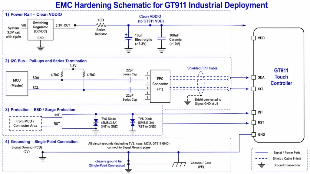
Durante a varredura ativa, o GT911 consome aproximadamente 30–80 mA da sua fonte VDD. A tensão de alimentação deve permanecer dentro de ±5% do valor nominal (tipicamente 2,8 V ou 3,3 V) em todas as condições de carga, incluindo a corrente de pico na partida a frio. Em sistemas industriais com trilhos de alimentação compartilhados, a exigência prática é um filtro local imediatamente nos pinos de alimentação do GT911.
Topologia de filtro recomendada: um resistor de 10 Ω em série com a alimentação, seguido por um capacitor eletrolítico de 10 µF e um capacitor cerâmico de 100 nF aterrados, posicionados a no máximo 5 mm dos pinos AVDD e VDDIO do GT911. Isso cria um filtro passa-baixa com uma atenuação de -3 dB em aproximadamente 1,6 kHz, reduzindo a ondulação do regulador de comutação (tipicamente entre 100 e 500 kHz) em mais de 40 dB. Meça a ondulação nos pinos de alimentação do GT911 com um osciloscópio de 200 MHz de largura de banda após a filtragem — o valor alvo deve ser inferior a ±50 mV pico a pico sob carga operacional máxima.
Endurecimento do barramento I²C
O barramento I²C transporta dados de toque a 400 kHz (modo rápido) entre o GT911 e o processador host. Nessa frequência, trechos de cabo com mais de 100 mm de comprimento começam a funcionar como antenas, captando interferências irradiadas. Três práticas previnem falhas na comunicação I²C em hardware de produção:
- Mantenha o comprimento do cabo I²C abaixo de 150 mm. Sempre que possível. Se o painel precisar ser fisicamente separado da placa de circuito impresso principal, use um cabo de par trançado blindado com a blindagem conectada ao terra em apenas uma extremidade.
- Adicionar 4,7 kΩ resistores pull-up para SDA e SCL na extremidade do host. Resistores de pull-up muito fracos (>10 kΩ a uma velocidade de barramento de 400 kHz) produzem bordas de subida lentas que se parecem com erros de dados quando há ruído presente.
- Coloque capacitores de terminação em série de 22 pF nos pinos SDA e SCL do conector de borda da placa de circuito impresso principal. Isso reduz a taxa de variação da borda o suficiente para diminuir as emissões irradiadas sem afetar a conformidade de temporização do I²C — uma técnica comumente usada em projetos certificados pela norma IEC 61000-4-4.
A norma IEC 61000-4-4 (imunidade a transientes/picos elétricos rápidos) é o padrão segundo o qual a maioria dos equipamentos de exibição industriais são testados para a marcação CE. O teste envolve transientes de pico de 2 kV aplicados às linhas de alimentação e de E/S. Os projetos que passam neste teste sem erros de comunicação GT911, utilizando a abordagem de filtragem descrita acima, normalmente também passam nos testes IEC 61000-4-2 (ESD) nível 3 e IEC 61000-4-6 (imunidade conduzida) nível 3 — as três normas mais relevantes para equipamentos IHM industriais.
Gestão térmica — Operação em toda a faixa de temperatura
A pilha LVGL + GT911, em funcionamento num ecrã tátil industrial 24 horas por dia, 7 dias por semana, gera três fontes de calor distintas que devem ser geridas: o conjunto de LEDs de retroiluminação (a fonte dominante), o processador principal (significativo durante a renderização intensiva em LVGL) e o circuito de leitura do controlador de toque (menor, tipicamente < 200 mW). Num invólucro industrial selado, todas as três fontes devem ser conduzidas para as paredes do invólucro — a convecção não é possível.
Carga térmica da luz de fundo
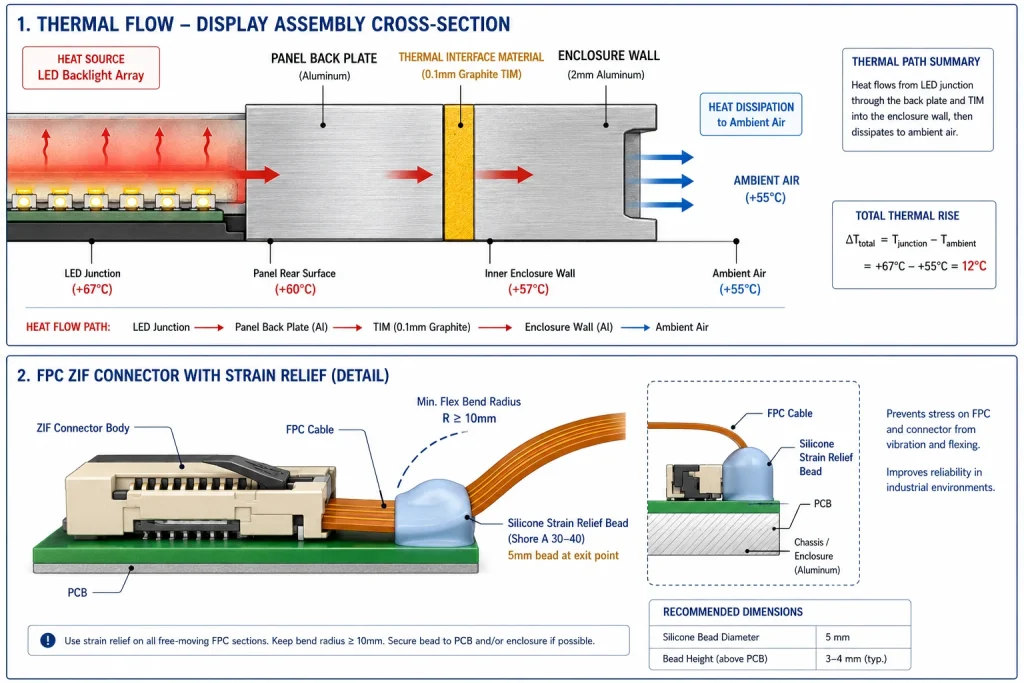
Um painel IPS de 7 polegadas com brilho de retroiluminação de 800 nits normalmente dissipa de 8 a 14 W da matriz de LEDs. Esse calor precisa percorrer o caminho das faixas de LED na borda do painel, através da placa traseira, sobre um material de interface térmica (TIM) e até a carcaça. O aumento de temperatura da temperatura ambiente até a junção dos LEDs é determinado por:
ΔT = P × (R_TIM + R_enclosure)
Onde P é a potência da luz de fundo (W), R_TIM é a resistência térmica da camada TIM (°C/W) e R_enclosure é a resistência térmica da parede interna da caixa até o ar ambiente (°C/W). Com uma camada TIM de grafite de 0,1 mm (R_TIM ≈ 0,05 °C/W por cm²) e uma parede de alumínio de 2 mm na caixa (R_enclosure ≈ 1,2 °C/W para um painel de 150 × 100 mm), uma luz de fundo de 10 W produz um aumento na temperatura de junção de aproximadamente 12 °C acima da temperatura ambiente. A +55 °C de temperatura ambiente (uma temperatura comum para painéis externos), a temperatura de junção do LED atinge cerca de 67 °C — bem dentro da classificação de 85 °C para LEDs de luz de fundo de qualidade, mas deixando apenas 18 °C de margem para variações de produção.
A regra prática de projeto: Especifique o escurecimento adaptativo e defina a potência da luz de fundo para, no máximo, 60% da potência nominal máxima durante a operação contínua.Isso mantém a temperatura de junção abaixo de 65 °C a uma temperatura ambiente de +55 °C com resistência térmica típica do gabinete, proporcionando uma margem de vida útil adequada. Os sistemas baseados em LVGL implementam isso por meio de um sensor de luz ambiente (ALS) que alimenta o controlador PWM da luz de fundo — abordado na seção de firmware.
Comportamento de partida a frio e resposta do fluido LCD
O fluido de cristal líquido nos painéis TFT-LCD apresenta viscosidade que aumenta drasticamente abaixo de 0 °C. Um painel LCD padrão ligado a −10 °C apresentará resposta lenta dos pixels — o display está tecnicamente ligado, mas o movimento parece estar sendo reproduzido a 10–15 fps, mesmo quando o framebuffer está sendo atualizado a 60 Hz. Essa é uma propriedade do material do fluido de cristal líquido, não um problema de firmware, e é imperceptível durante o desenvolvimento de demonstrações realizadas em temperatura ambiente.
Para implantações que incluem cenários de inicialização a frio — quiosques externos, displays montados em veículos, terminais de armazém em instalações refrigeradas — duas abordagens são aplicáveis:
- Especificação de painel para ampla faixa de temperaturaOs painéis IPS com formulações de fluido LC estendidas mantêm um tempo de resposta ≥5 ms até −20°C. Esses painéis são especificados de forma diferente dos painéis IPS comerciais padrão; verifique explicitamente a especificação do tempo de resposta em baixa temperatura com o fornecedor do seu painel.
- Película de aquecimento atrás do LCDUm elemento de aquecimento resistivo, fixado na face traseira do painel e controlado por um termistor, mantém a temperatura do painel acima do limite mínimo de operação em condições de frio ambiente. A potência típica do aquecedor é de 5 a 10 W; ele é ativado abaixo de +5 °C e desativado acima de +15 °C. O aquecedor deve ser alimentado pela mesma fonte de alimentação regulada do painel para evitar que transientes de tensão durante a comutação do aquecedor interfiram na calibração do GT911.
Ciclos térmicos e confiabilidade do conector FPC
A variação de temperatura — o ciclo diário de uma temperatura ambiente fria durante a noite para uma temperatura operacional quente — produz tensão mecânica nos conectores FPC (cabo impresso plano) entre a película de contato e a placa de circuito impresso (PCB). A diferença no coeficiente de expansão térmica (CTE) entre o substrato FR4 da PCB (CTE ≈ 17 ppm/°C) e o FPC de poliimida (CTE ≈ 20 ppm/°C) produz um movimento relativo de aproximadamente 0,03 mm por centímetro de comprimento do cabo a cada variação de temperatura de 50 °C. Ao longo de milhares de ciclos, isso tensiona os contatos do conector ZIF (força de inserção zero).
Mitigação na produção: aplique um cordão de alívio de tensão com adesivo de silicone de baixa dureza (Shore A 30–40) no ponto onde o FPC sai do corpo do conector ZIF. Esta etapa de produção de 5 minutos reduz drasticamente as falhas em campo relacionadas ao FPC em instalações submetidas a ciclos térmicos. Inspecione esta junção como parte do seu processo de controle de qualidade de entrada para módulos de tela montados.
Testes de envelhecimento acelerado e validação por envelhecimento acelerado
O envio do primeiro lote de produção sem testes de envelhecimento acelerado é o erro mais comum no desenvolvimento de interfaces homem-máquina (IHM) industriais. As falhas de componentes seguem a conhecida curva da banheira: a taxa de falhas é elevada durante o período inicial de vida útil (mortalidade infantil), cai para uma taxa baixa e estável durante a vida útil operacional e, em seguida, volta a subir à medida que os componentes se desgastam. Um teste de envelhecimento acelerado de 24 horas em temperatura elevada elimina as falhas de mortalidade infantil antes que o produto chegue ao cliente.
Protocolo de Burn-In para Sistemas GT911 + LVGL
Um protocolo de teste de funcionamento contínuo (burn-in) para uma tela sensível ao toque industrial 24 horas por dia, 7 dias por semana, deve abranger todos os modos de falha afetados pela mortalidade infantil:
� Indústria Linha de base — O que o teste de burn-in de 24 horas detecta
Dados de campo de fabricantes de displays integrados indicam que o teste de envelhecimento acelerado a +65°C por 24 horas detecta aproximadamente 68% das falhas que, de outra forma, apareceriam nas primeiras 500 horas de operação em campo. Os modos de falha mais comuns identificados foram: solda fria no controlador de toque (23% das falhas detectadas), contato intermitente no conector FPC (31%), instabilidade do driver de backlight sob carga térmica (18%), travamento do endereço I²C do GT911 em circuito de reset marginal (15%) e loop de reset do watchdog LVGL em falha de alocação de memória (13%).
Dados de campo de fabricantes de displays integrados indicam que o teste de envelhecimento acelerado a +65°C por 24 horas detecta aproximadamente 68% das falhas que, de outra forma, apareceriam nas primeiras 500 horas de operação em campo. Os modos de falha mais comuns identificados foram: solda fria no controlador de toque (23% das falhas detectadas), contato intermitente no conector FPC (31%), instabilidade do driver de backlight sob carga térmica (18%), travamento do endereço I²C do GT911 em circuito de reset marginal (15%) e loop de reset do watchdog LVGL em falha de alocação de memória (13%).
Validação automatizada da precisão do toque
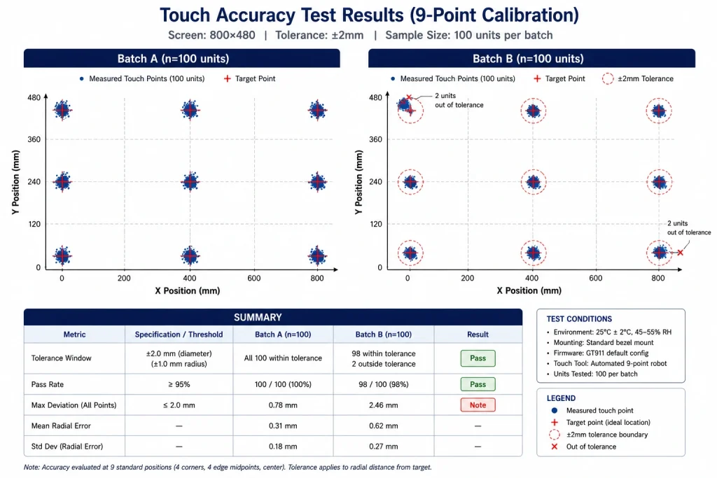
O teste de toque humano durante o período de burn-in é impraticável e inconsistente. A validação de toque em escala de produção requer um dispositivo de teste — um acessório que move uma caneta condutora (ou conjunto de canetas) para coordenadas conhecidas na superfície da tela sensível ao toque sob força controlada (tipicamente 150–250 gf, equivalente à norma IEC 60068-2-75), lê a coordenada reportada pelo firmware do host e registra o erro.
A matriz de teste mínima para validação de toque do GT911 PCAP consiste nos quatro cantos da área ativa, nos quatro pontos médios das bordas e no centro — totalizando nove pontos. Em cada ponto, meça 20 eventos de toque e calcule o erro absoluto médio e o desvio padrão. Especificação de produção aceitável para IHM industrial: Erro médio < 2 mm, desvio padrão < 0,8 mm, em todos os nove pontos, tanto a +25°C quanto a +65°C. Qualquer unidade que não atinja esses limites indica um problema de registro da película de toque que pode ser corrigido por meio de recalibração via registro de configuração GT911 0x8047–0x80FF — mas somente se a montagem mecânica subjacente estiver em condições aceitáveis.
Consistência tátil em todos os lotes de produção
Uma calibração de toque GT911 que funciona perfeitamente no primeiro lote de produção pode precisar de ajustes no segundo lote se o fornecedor entregar painéis com espessura de película de toque ou constante dielétrica ligeiramente diferentes. Isso não é uma falha de qualidade — é uma variação normal dentro das especificações do componente — mas requer uma etapa de validação da calibração na inspeção de qualidade de entrada, que muitas equipes ignoram.
Registros de configuração do GT911 — O que muda entre lotes?
O bloco de configuração de 186 bytes do GT911 (registradores 0x8047–0x80FF) contém parâmetros que definem como o controlador interpreta as medições de capacitância bruta como eventos de toque. Três registradores são responsáveis pela maior parte da variação no comportamento de toque entre lotes:
Implementando uma etapa de verificação de configuração em TIC
O teste em circuito (ICT) ou teste funcional no final da linha de montagem da placa de circuito impresso é o local ideal para validar a configuração do GT911. A sequência de teste é a seguinte: ligar a placa, ler o bloco de configuração completo do GT911 via I²C, comparar com a configuração de referência armazenada no sistema de teste, sinalizar qualquer desvio e, opcionalmente, gravar o bloco de configuração corrigido e o checksum verificado antes que a unidade prossiga para a montagem final.
Arquitetura Watchdog de Firmware para Operação 24/7
Uma tela sensível ao toque que funciona corretamente por 23 horas e 59 minutos, mas precisa ser reiniciada após 24 horas, não é um monitor industrial para operação 24 horas por dia, 7 dias por semana — é um dispositivo que, por acaso, fica ligado continuamente. O firmware deve ser explicitamente projetado para operação indefinida e sem supervisão, o que significa tratar cada componente de software como uma fonte potencial de falha e projetar mecanismos de recuperação para cada um deles.
A Hierarquia de Vigilância de Três Camadas
O firmware embarcado robusto, que opera 24 horas por dia, 7 dias por semana, utiliza uma arquitetura de watchdog em camadas em vez de um único temporizador de watchdog de hardware:
Recuperação I²C do GT911 — Lidando com o bloqueio do barramento
Um dos problemas de confiabilidade mais persistentes em implantações do GT911, que exigem operação 24 horas por dia, 7 dias por semana, é o travamento do barramento I²C: um cenário em que uma interrupção transitória de energia ou um evento de descarga eletrostática (ESD) deixa o GT911 em pleno sinal de transmissão, mantendo o sinal SDA em nível baixo e impedindo qualquer comunicação I²C subsequente. O watchdog de hardware não consegue detectar essa condição porque o firmware está funcionando normalmente — ele apenas fica travado aguardando o sinal I²C.
A sequência de recuperação deve ser implementada em software e acionada por erros de tempo limite I²C:
⚠ Pista Eventos de recuperação em logs não voláteis
Cada evento de recuperação automática — reinicialização do barramento I²C, reinicialização do watchdog LVGL, WDT de hardware — deve ser registrado no NVS (Armazenamento Não Volátil) com um carimbo de data/hora e um código de evento. Quando uma unidade de campo é devolvida para investigação, esse registro revela se o hardware está apresentando falhas intermitentes ou uma falha sistêmica. Sem esse registro, a análise da causa raiz de problemas de confiabilidade 24 horas por dia, 7 dias por semana, é baseada em suposições.
Cada evento de recuperação automática — reinicialização do barramento I²C, reinicialização do watchdog LVGL, WDT de hardware — deve ser registrado no NVS (Armazenamento Não Volátil) com um carimbo de data/hora e um código de evento. Quando uma unidade de campo é devolvida para investigação, esse registro revela se o hardware está apresentando falhas intermitentes ou uma falha sistêmica. Sem esse registro, a análise da causa raiz de problemas de confiabilidade 24 horas por dia, 7 dias por semana, é baseada em suposições.
Atualizações de firmware OTA — Mantendo sistemas operacionais 24 horas por dia, 7 dias por semana.
Um painel touchscreen industrial que opera 24 horas por dia, 7 dias por semana, e exige acesso físico para atualizações de firmware, representa um problema operacional em larga escala. Unidades implantadas em instalações remotas, frotas de veículos ou redes de quiosques não tripulados necessitam de um mecanismo de atualização OTA (over-the-air) confiável que mantenha a disponibilidade ininterrupta durante todo o processo de atualização.
Atualização OTA segura para sistemas de exibição LVGL
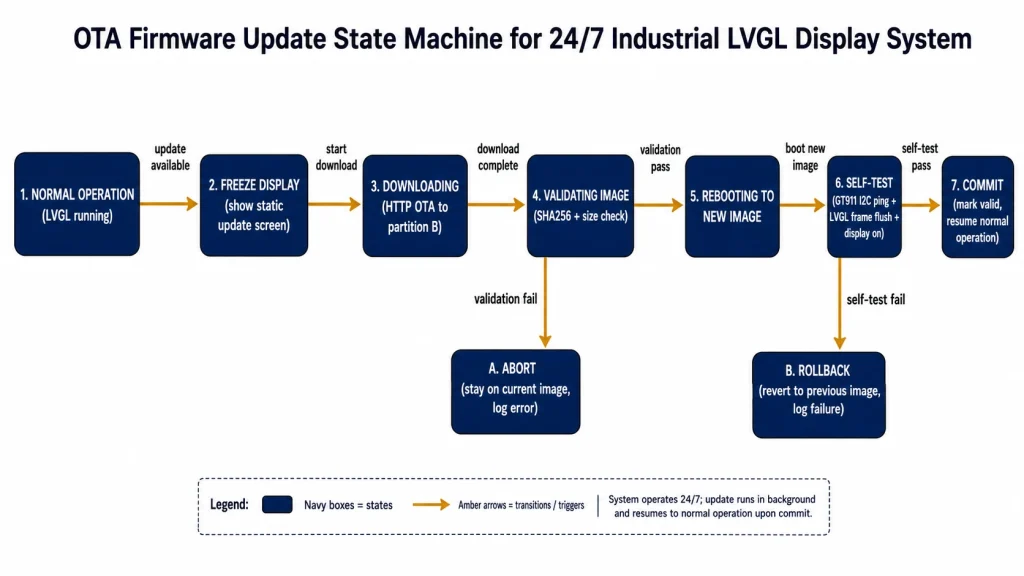
O mecanismo de atualização OTA do ESP-IDF grava a nova imagem de firmware em uma partição OTA secundária enquanto a imagem atual continua em execução e, em seguida, valida a nova imagem antes de confirmá-la. Isso proporciona atualizações atômicas — se a nova imagem não inicializar, o bootloader reverte automaticamente para a versão anterior. Para sistemas de exibição, considerações adicionais se aplicam:
- Congelar a tela durante o download OTA — A renderização LVGL durante um download OTA HTTP compete pela largura de banda da PSRAM com o DMA de download. Exibir uma tela estática de "Atualização em andamento" (um único lv_label em um fundo sólido) reduz o tráfego da PSRAM do LVGL a quase zero e elimina a principal fonte de corrupção de downloads OTA em sistemas com tela.
- Verifique a tela e a função de toque antes de confirmar. — após a nova imagem ser inicializada pela primeira vez, execute uma sequência de autoteste antes de chamar esp_ota_mark_app_valid_cancel_rollback()O autoteste deve confirmar: comunicação I²C com GT911 (leitura do registrador de ID do produto 0x8140), conclusão do flush do quadro RGB em 200 ms e execução de LVGL lv_timer_handler() sem falha.
- Agende atualizações durante períodos de baixa atividade. — O monitoramento adaptativo de brilho e atividade do LVGL pode identificar períodos sem interação por toque (normalmente durante a noite). Os downloads OTA iniciados durante esses períodos evitam interromper os operadores ativos.
Gerenciamento de firmware e configuração do GT911
Os registros de configuração do GT911 são armazenados na memória interna do controlador, semelhante à memória OTP, e persistem mesmo após o desligamento e religamento do dispositivo. Quando uma atualização de firmware altera o layout da interface do usuário LVGL de forma que modifique os requisitos de sensibilidade ao toque (por exemplo, adicionando alvos de toque menores que exigem maior sensibilidade do GT911), a configuração do GT911 deve ser atualizada como parte da atualização do firmware do aplicativo.
Melhor prática: armazene o bloco de configuração do GT911 de destino na imagem do firmware do ESP32 como um array constante. A cada inicialização, após a inicialização do GT911, leia a configuração atual, compare o checksum com o checksum da configuração de destino e, se forem diferentes, grave a configuração de destino e reinicie o GT911. Isso garante que a configuração do GT911 permaneça sincronizada com a versão do firmware durante as atualizações OTA, sem a necessidade de uma etapa separada de atualização do firmware do GT911.
Selecionando um fornecedor de painéis para compromissos de produção 24 horas por dia, 7 dias por semana.
As decisões de hardware tomadas durante o projeto — especificamente a combinação de módulo de tela e painel de toque escolhida — determinam o limite máximo de confiabilidade que o firmware pode alcançar. Um painel que apresenta degradação prematura da luz de fundo, calibração GT911 inconsistente de fábrica ou problemas de qualidade no conector FPC gerará falhas em campo que nenhum monitoramento de firmware ou atualização OTA poderá resolver.
Critérios essenciais para qualificação de fornecedores no fornecimento de displays industriais 24 horas por dia, 7 dias por semana:
Kadi Display s módulos de tela sensível ao toque TFT-LCD industriais Incluem configurações com controladores GT911 calibrados de fábrica, tecnologia de painel IPS com amplos ângulos de visão e operação em ampla faixa de temperatura. Para equipes de design de produto que avaliam a estética do painel juntamente com a confiabilidade, o guia deles sobre Design personalizado de vidro de cobertura e tela sensível ao toque industrial Abrange toda a gama de opções de personalização de vidro para gabinetes de IHMs industriais de marca. A seleção da tecnologia de painéis é abordada em detalhes em seu documento. Guia comparativo TN vs IPS vs VA — Contexto relevante para equipes que precisam escolher entre diferentes tipos de painel para ambientes de visualização 24 horas por dia, 7 dias por semana.
Lista de verificação de prontidão para produção
Uma revisão estruturada antes do primeiro envio de produção. Cada item representa uma lacuna que causou falhas reais em campo em implantações de IHM (Interface Homem-Máquina) industriais:
Referência de produto e suporte técnico
Para módulos de tela sensível ao toque TFT-LCD de nível industrial com sensibilidade ao toque GT911 calibrada de fábrica, tecnologia de painel IPS, operação em ampla faixa de temperatura e compromissos de fornecimento contínuo adequados para implantações industriais 24 horas por dia, 7 dias por semana, entre em contato com a Kadi Display. Sales@sz-kadi.comServiços OEM e ODM disponíveis, incluindo vidro de cobertura personalizado, colagem óptica e especificações de painéis para ampla faixa de temperatura. Veja os módulos de tela sensível ao toque TFT industriais →
Para módulos de tela sensível ao toque TFT-LCD de nível industrial com sensibilidade ao toque GT911 calibrada de fábrica, tecnologia de painel IPS, operação em ampla faixa de temperatura e compromissos de fornecimento contínuo adequados para implantações industriais 24 horas por dia, 7 dias por semana, entre em contato com a Kadi Display. Sales@sz-kadi.comServiços OEM e ODM disponíveis, incluindo vidro de cobertura personalizado, colagem óptica e especificações de painéis para ampla faixa de temperatura. Veja os módulos de tela sensível ao toque TFT industriais →
Isenção de responsabilidade: Os exemplos de código e os dados de taxa de falhas neste guia são para fins educacionais e derivam da experiência geral da indústria. Valores específicos (tempos limite do watchdog, valores dos componentes do filtro, limites de temperatura) devem ser validados para cada ambiente de implementação e configuração de hardware. As referências às normas IEC são incluídas para contexto informativo; os testes de conformidade devem ser conduzidos por um laboratório de testes acreditado. GT911 é uma marca registrada da Shenzhen Goodix Technology Co., Ltd. ESP32-S3 é uma marca registrada da Espressif Sistemas. LVGL é um projeto de código aberto sob a licença MIT. Todas as outras marcas registradas pertencem aos seus respectivos proprietários.
PRIVENTE
Como conectar um painel de toque capacitivo GT911 ao LVGL no ESP32-S3
NEXTO
Telas Raspberry Pi para IHM Industrial
Deixe um comentário

Recent Blog & News
- Industrial LCD EOL: What Happens from Pre-Announcement to Replacement Mass Production?
- Electronic Component Obsolescence Management for Industrial Displays: An OEM Guide
- How to Develop a Production Ready Custom Display Assembly TFT Module Touch Cover Glass FPC Bonding and Mounting
- 15 Pin vs 22 Pin Raspberry Pi DSI Connectors Cable Pinout and Compatibility
- Native MIPI DSI vs LVDS or HDMI Bridge: An OEM Display Architecture Decision Guide

