
EV Charger Display Integration With One Custom Cable Harness
2026-11-19
12:00
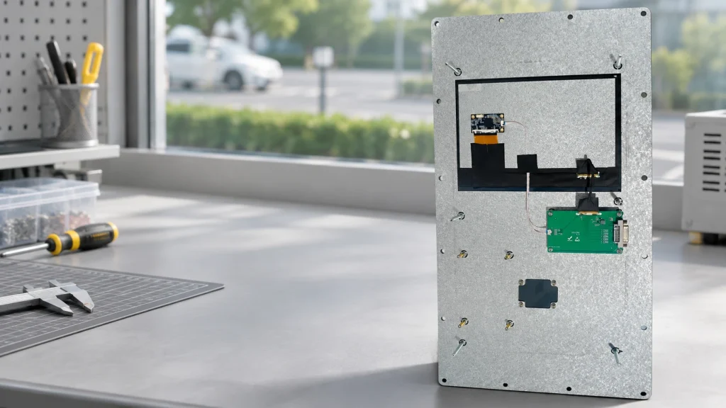
An EV charger display can use one custom harness to carry LVDS image data, backlight power and control, touch communication, and panel power. The simplification comes from consolidating the connection between the host and display assembly while preserving the electrical requirements of each circuit. It does not require the internal LCD, touch controller, and interface board to become a single component.
In a Kadi Display outdoor charging project, three separate cable groups for LVDS, backlight, and I2C were packaged into one harness. That is a concrete change in connection architecture. Applying the same approach to another charger starts with understanding where those connections run and what the installed display must withstand.
Define what the single harness replaces
Begin with a connection diagram showing the host board, LCD, touch controller, backlight circuit, and power sources. Mark the boundary where the display assembly connects to the charger. Count cable groups at that boundary separately from short internal connections. Otherwise, a claim about one harness can be mistaken for a claim that every internal wire has disappeared.
In this project, the original arrangement used an LVDS cable group, a backlight cable group, and an I2C cable group. The backlight path included both power and dimming functions. Power therefore belongs in the functional description, but it should not be counted as a fourth original cable without evidence.
A useful design review asks which connections an installer handles during final assembly and which remain inside the supplied display assembly. That distinction also determines what a service technician disconnects when replacing the screen.
Preserve the separate electrical jobs
Sharing an outer harness does not make LVDS, touch communication, and power electrically interchangeable. LVDS uses differential signal pairs. I2C touch communication uses clock and data lines with timing and loading limits. Backlight enable and PWM dimming are control signals, while the power conductors must support their assigned loads.
Keep these functions identifiable in the schematic and pin assignment. Review pair polarity, signal mapping, voltage domains, ground references, and startup behavior before choosing the connector. The host must also provide the panel timing and touch support expected by the selected assembly.
This is a different decision from selecting a video interface for a new processor board. The objective is to preserve an established interface through a more convenient connection. A cable package cannot correct an unsupported panel timing, an incompatible logic level, or a missing touch driver.
Design the connection around the installed route
The shortest line between two connectors in CAD may be unusable in the charger. The real route must clear the mounting bracket, fastening tools, door hardware, seals, and neighboring electronics. Include the connector body, cable exit, retention hardware, and bend space in the model.
Check the route during installation and removal as well as normal operation. A service loop should provide access without loading a small board connector or folding a flexible circuit against an edge. Moving a loop away from a seal may be more valuable than reducing its nominal length.
For the wider mechanical context, Kadi Display’s industrial display stack design guide explains how the LCD, touch panel, PCB, and enclosure share space and loads. Harness routing should be reviewed against that same assembly geometry.
Treat the DVI connector as a custom interface
The project uses a DVI connector with project-specific pin assignments. Its familiar shape does not establish compatibility with a conventional DVI video port or an ordinary DVI cable. Here, the assigned contacts carry the display assembly’s LVDS, power, backlight, and touch-related circuits.
The mating host connection must follow the released project drawing. Label both ends so an installer can identify the approved connection without relying on appearance. Replacement instructions should identify the harness revision and mating equipment, especially where similar connectors exist elsewhere in the cabinet.
A connector drawing also needs a clearly stated viewing direction. A pin map viewed from the mating face can appear reversed when compared with a wiring-side view. Resolve that ambiguity on the drawing before samples are energized.
Keep outdoor optical requirements in the same project review
Reducing cable groups addresses integration, while outdoor readability and UV exposure remain separate requirements. The screen must still present useful contrast through its complete cover and touch stack. Brightness alone does not describe the reflections seen by a person standing in front of the charger.
Optical bonding can reduce reflections at internal interfaces by filling an air gap. Material choice, edge conditions, and the finished stack still need evaluation. The optical bonding and air bonding comparison covers that separate optical decision in more detail.
UV protection also needs a defined scope. A UV-blocking adhesive can help protect layers behind it, but its material data does not establish the outdoor life of the complete display. Likewise, a front-panel ingress rating does not describe the protection of exposed rear electronics or the harness connection.
Verify the complete assembly with the host
Start with unpowered checks of pin mapping, continuity, unintended shorts, and polarity. Then verify the assigned power rails and startup sequence before enabling the display. A powered image test should use the intended host, display timing, and production-intent cable route.
Exercise touch input while changing backlight brightness and while representative charger functions operate. This helps reveal interactions that a static image cannot show. Record image disturbances, touch interruptions, unexpected resets, and intermittent behavior during permitted cable movement.
Acceptance should include mechanical checks: access to retention hardware, strain relief, clearance from sharp edges, and repeatable installation. Environmental and electromagnetic tests should match the finished charger’s requirements. Passing a continuity check establishes wiring correctness, not full system compatibility.
What the outdoor charging project demonstrates
The Kadi Display project combined the three original cable groups into one harness for an outdoor display assembly. The confirmed configuration was a 10.1-inch, 1280 × 800 display with 850 cd/m² typical brightness, 10-point capacitive touch, an IK08 specification, and an operating range of -20°C to +70°C. These describe this project rather than a universal outdoor charger specification.
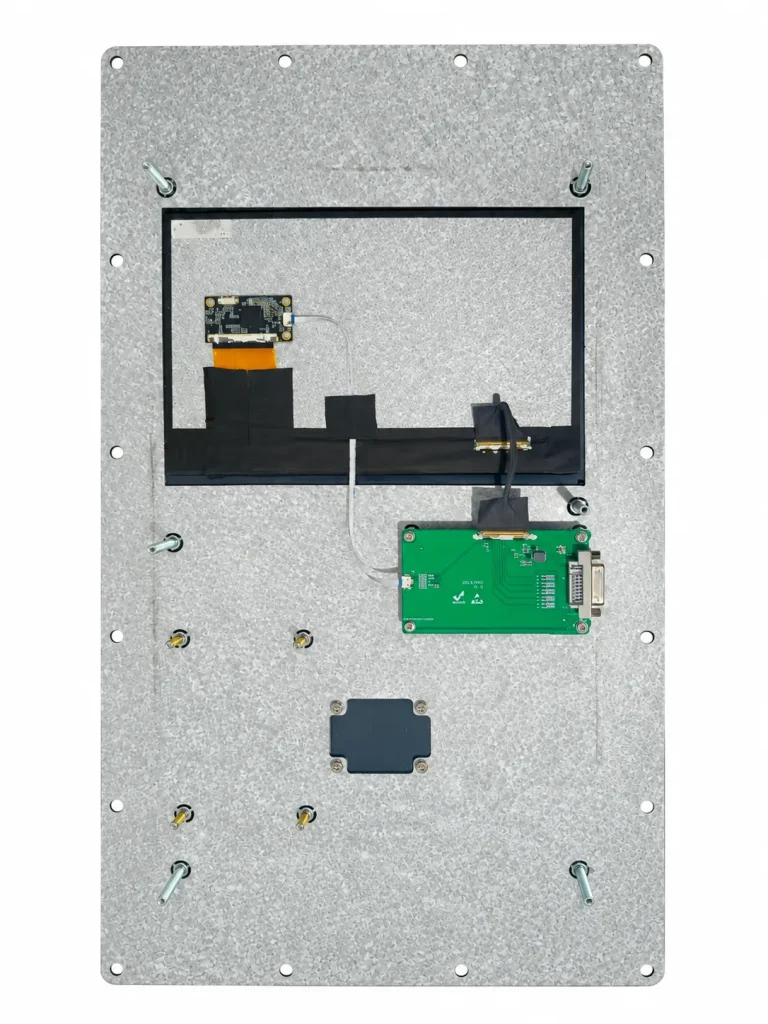
The optical stack used G6610 OCA for UV protection. The IP65 scope was the front panel. The modified rear assembly retained internal display and touch connections around the interface PCB, consistent with consolidation at the host connection rather than elimination of all internal wiring.
The demonstrated result is three cable groups packaged as one harness. Assembly-time savings, cost reductions, and field-failure improvements have not been quantified for this case. An OEM evaluating a similar change should measure those outcomes in a pilot build rather than assigning assumed savings to the cable count.
Ofertas de Kadi Display project-based display customization covering cables, interfaces, touch, bonding, controller boards, and housing. The relevant starting point is the complete application, including the existing host and service arrangement.
Conclusión
One custom harness can simplify EV charger display integration when its electrical mapping, physical route, and service boundary are designed together. The useful outcome is a clearer, controlled connection between assemblies. Outdoor optical performance, front-panel protection, and system validation still need their own requirements and evidence.
Frequently asked questions
Does one harness mean there is only one internal wire?
No. A consolidated host connection can coexist with internal LCD, touch, and interface-board connections. Define the connection boundary before comparing cable counts.
Can a standard DVI cable replace this harness?
Connector appearance is insufficient. This project uses custom pin assignments, so a replacement must match the released electrical and mechanical specification.
Does the harness make the whole display IP65?
No. This project’s IP65 scope is the front panel. Rear protection and connector exposure must be addressed in the charger enclosure design.
What information starts a similar integration review?
Provide the host and panel specifications, touch interface, power requirements, current wiring, mating connector details, cable route, and outdoor operating conditions.
To assess a comparable project, request an integration review from Kadi Display with those drawings and specifications, plus the expected sample and production quantities.
PREVIOR
No más
Siguiente
What to Ask an Industrial Display Manufacturer Before Design-In: Lifecycle, EOL, and Customization
Deja un comentario

Últimos blogs y noticias
- EV Charger Display Integration With One Custom Cable Harness
- What to Ask an Industrial Display Manufacturer Before Design-In: Lifecycle, EOL, and Customization
- LCD Display Module vs Custom Display Assembly: What Does an OEM Actually Need?
- Industrial Display Obsolescence Management Plan Template: BOM, PCN, EOL, LTB, and Validation
- How to Build Supply Chain Resilience for Long-Lifecycle Industrial Display Projects