




MIPI DSI Display Bring-Up Checklist: Eight Evidence Gates
2026-08-01
11:48
MIPI DSI Display Bring-Up Checklist: Eight Evidence Gates
A disciplined sequence for power, reset, D-PHY state, lanes, commands, video timing, test patterns, and backlight
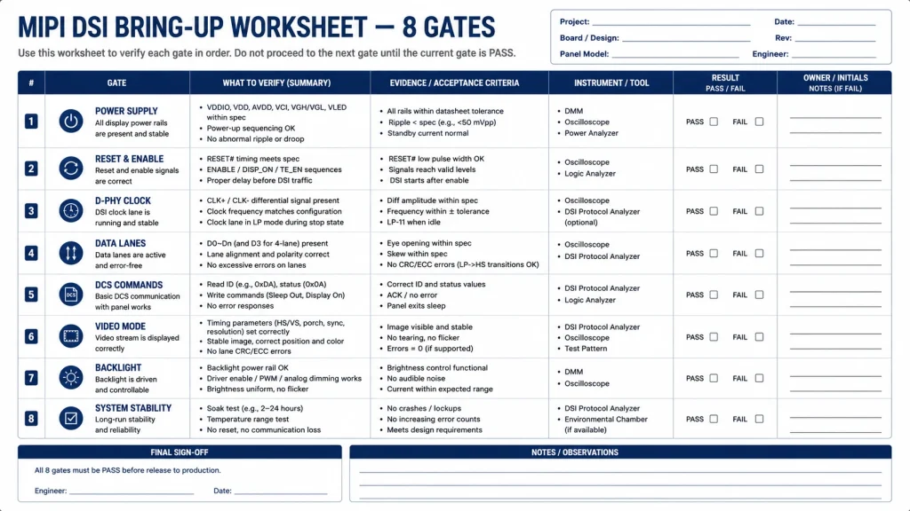
A black MIPI DSI display should be debugged from the physical dependencies upward. This checklist turns bring-up into eight evidence gates so engineers stop changing panel commands while power, reset, lane configuration, or video timing remains unverified.
Start with the Dependency Chain, Not the Symptom
Direct answer — Prove power and reset first, then PHY state and lane configuration, then commands and video timing, and only then enable the backlight. Record a pass criterion and measurement for every gate.
Related Kadi Display reference: Kadi Display’s MIPI platform support guide.
The single most common failure pattern in MIPI DSI display bring-up for industrial HMI projects is not a hardware defect or a software bug — it is debugging the wrong layer. Engineers spend hours adjusting initialization commands when the actual problem is an unstable power rail. They rewrite DMA configurations when the clock lane is misconfigured. They suspect panel defects when the reset timing violates the driver IC’s minimum pulse width.
This checklist is organized as a strict sequence: each step must be verified independently before moving to the next. The sequence follows the physical signal path from power supply through to backlight output, matching the actual dependency chain within the display subsystem.
Industrial HMI projects carry additional bring-up risk because the panel is often custom-configured, the development hardware may differ from production hardware, and timeline pressure makes systematic debugging feel slower than trial-and-error — even though trial-and-error consistently takes longer in total hours.
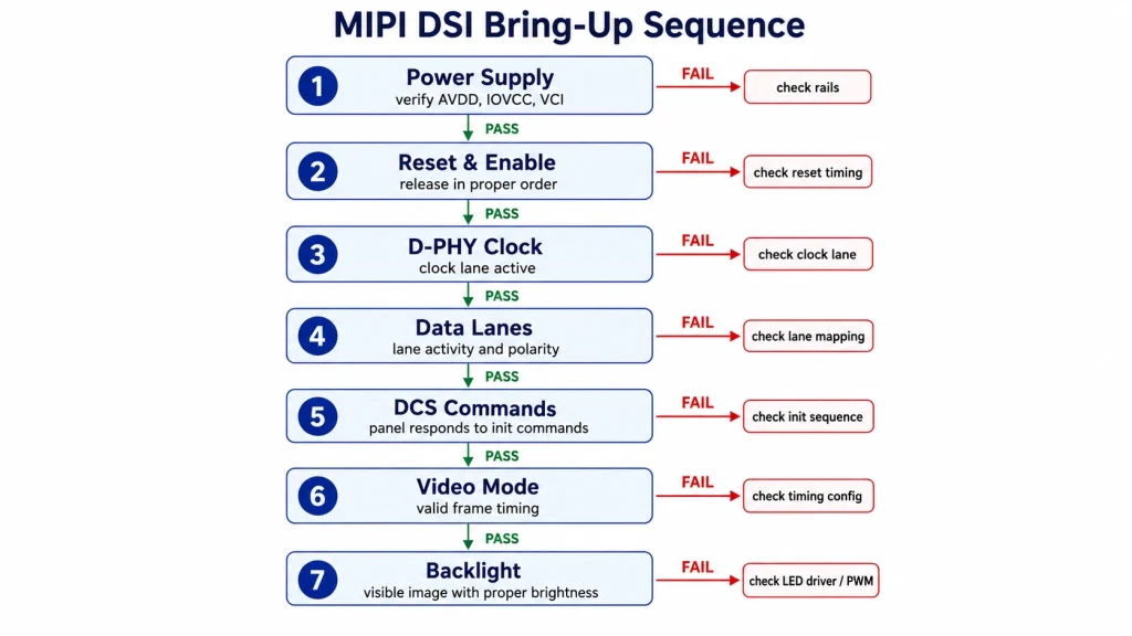
Gate 1 — Power Rails and Sequencing
Before any digital signal reaches the panel, verify every externally supplied rail named in the module drawing. Some modules expose only logic and backlight power because bias rails are generated internally; others expose additional analog rails. Never copy a generic VCC/AVDD/VGH/VGL list into a design without the exact pinout.
Measure each required rail at the connector under the intended load and capture ramp order, overshoot, ripple, and brownout behavior. Start with the panel disconnected only when the hardware can be measured safely; then repeat with the panel connected and current limits set for the documented inrush.
Gate 2 — Reset, Standby, and Enable Timing
With power rails confirmed, capture reset, standby, and enable relative to the rails. Use the panel-controller datasheet or supplier sequence for pulse width and delays; a generic 10 ms or 50 ms value is not a universal requirement.
Verification method: Capture the reset pin with an oscilloscope triggered on VCC rising edge. Verify pulse width, post-reset delay, and absence of glitches.
Gate 3 — D-PHY Clock State and PLL
Clock-mode caution — Continuous versus non-continuous clock is a negotiated implementation choice, not a universal industrial default. Use the panel and host documentation, then confirm the programmed state and receiver behavior.
Related Kadi Display reference: Kadi Display’s D-PHY and PCB layout guide.
For conventional forwarded-clock D-PHY, the clock lane and data lanes must enter valid low-power and high-speed states according to the host and panel configuration. Newer PHY options and some hosts use different clock behavior, so diagnose the actual implementation rather than assuming one waveform.
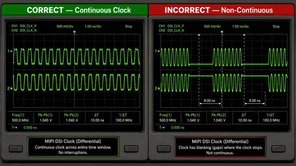
Gate 4 — Lane Count, Mapping, and Error Status
Confirm the configured data-lane count, polarity, lane mapping, and data rate at both endpoints. Read host error/status registers before concluding that a mismatch is silent; many controllers expose PLL, timeout, ECC, CRC, or lane-state evidence even when the panel remains blank.
Lane remapping and polarity inversion support are host-specific. Check the exact controller documentation and board schematic before treating a layout error as software-correctable.
Gate 5 — Panel Initialization Commands
This step consumes the most debugging time — often unnecessarily, because failures here frequently root in steps 1–4.
Panel initialization commonly combines standard DCS commands with controller- or module-specific register writes. The supplier sequence must identify packet type, payload, low-power/high-speed state, and delays. Use the panel documentation for the delay after Sleep Out; do not assume every controller requires the same 120 ms interval.
Gate 6 — Video Timing and Controlled Test Pattern
After init commands complete, the host must output continuous pixel data in the correct Video Mode format.
HBP, HFP, HSW, VBP, VFP, and VSW must match an allowed timing set. A shifted or unstable image can arise from timing, lane rate, packet mode, or color-format mismatch, so log the complete configuration rather than changing one porch in isolation.
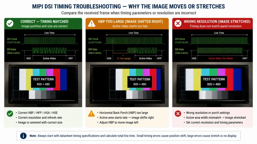
Gate 7 — Backlight, Brightness, and Thermal Check
Backlight gate — Choose PWM frequency from the LED driver, dimming range, acoustic requirement, camera environment, EMC plan, and thermal measurement. A blanket 20 kHz minimum is not a substitute for system validation.
Related Kadi Display reference: Kadi Display’s Raspberry Pi DSI troubleshooting workflow.
A successfully initialized panel still appears dark without backlight. Backlight control is electrically separate from DSI.
Quick-reference evidence record
All seven steps as pass/fail gates:
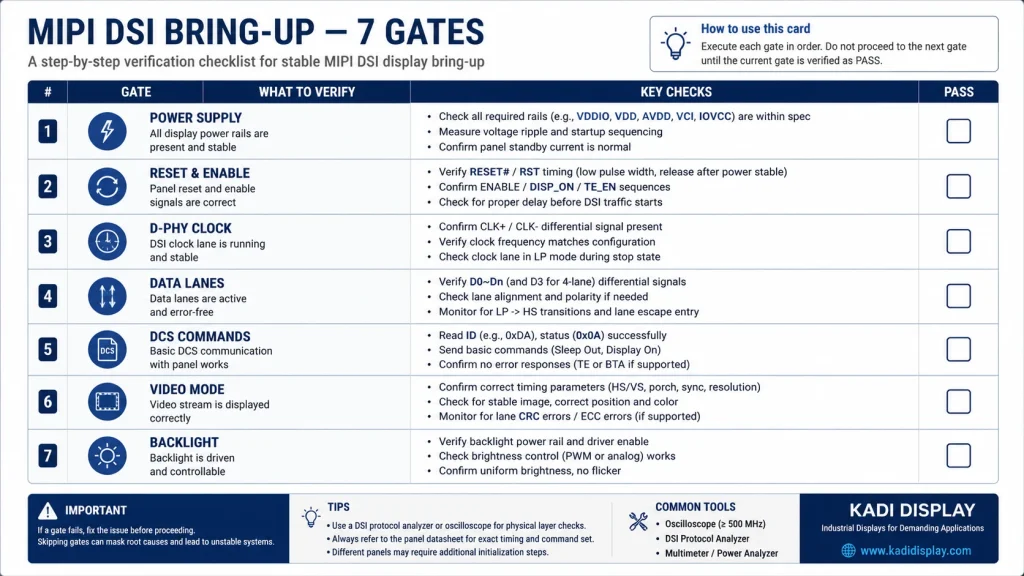
Summary — Seven Gates Between Power-On and a Working Display
The bring-up record should include schematic revision, panel revision, init-sequence revision, host register dump, measured rail/reset waveforms, lane configuration, timing structure, test-pattern result, and environmental condition. That record turns a one-off success into a repeatable production process.
When a change fixes the display, revert it once to prove causality. If three parameters are changed together, the team learns only that one of them mattered. Small reversible changes—one rail, one delay, one lane setting, or one timing field—produce defensible evidence.
A working image is not the end of bring-up. Repeat cold start, warm restart, brownout recovery, firmware update, maximum brightness, and representative temperature tests before calling the integration complete.
Gate reviews should have owners. Hardware owns measured rails, reset, connector orientation, lane routing, and the physical clock/data channel. Firmware owns host state, packet construction, command order, delays, timing registers, and error logs. System engineering owns backlight behavior, boot experience, recovery, and environmental validation. Clear ownership prevents the same symptom from circulating between teams.
At the power gate, capture the waveform at the panel connector rather than only at the regulator. Cable resistance, connector contact, filtering, and inrush can make the panel-side waveform materially different. Record voltage scale, time scale, probe ground method, trigger point, temperature, and sample identity so another engineer can reproduce the capture.
At the reset gate, verify logic levels during host boot. GPIOs may be high impedance before firmware configures them, boot ROMs can toggle pins, and shared reset nets can be disturbed when another peripheral initializes. A successful manual reset after boot but failed cold start often points to this interval. Add pulls or sequencing only after confirming the panel’s allowed behavior.
At the PHY gate, inspect controller status before reaching for a high-bandwidth probe. Confirm PLL lock, selected lane count, stop state, escape-mode activity, and reported timeouts or ECC/CRC errors. Then use suitable measurement equipment and probing only if the board provides access and the procedure will not load or damage the lane.
At the command gate, convert the supplier byte array into a readable transaction log. Label DCS versus generic writes, short versus long packets, command page changes, payload length, delay, and expected readback. This makes revision comparison possible and reveals missing unlock sequences or commands sent in the wrong state.
At the video gate, calculate timing from one controlled source. Store Hactive, HFP, HBP, HSW, Vactive, VFP, VBP, VSW, pixel format, refresh, lanes, and lane rate together. Copying porches from one file and lane rate from another creates configurations that have never existed in the panel documentation.
At the backlight gate, separate optical appearance from panel state. A flashlight test can reveal an image on an unlit LCD, but it is only a diagnostic clue. Measure enable, PWM or analog dimming, LED current, driver protection state, startup delay, and temperature. Confirm that failure recovery does not repeatedly flash a full-brightness uninitialized frame.
Close bring-up with reproducibility. A second engineer should be able to assemble another sample, flash the same build, follow the record, and obtain the same result. If success depends on one board, one cable position, or a manual delay inserted through a debugger, the integration is still experimental.
Evidence Package and Release Control
Before releasing a mipi dsi bring-up design, convert the article’s guidance into a requirements matrix. Give every requirement an owner, source, revision, unit, tolerance, verification method, sample quantity, and acceptance rule. This prevents an informative article from being mistaken for a product specification and makes unanswered questions visible while changes are still inexpensive.
Separate documented limits from planning assumptions. A datasheet value, vendor application note, calculated estimate, measured prototype result, and internal design target do not have the same authority. Label each one. When a value is only representative, record the condition that would make it change and identify the exact document or test that must replace it before production release.
Use production-intent samples for the final decision. Evaluation boards, hand-selected cables, open-bench wiring, laboratory power supplies, and debug firmware can hide tolerance and assembly problems. Repeat the relevant checks with approved component alternatives, final connector and flex routing, enclosure constraints, released clock and power settings, and the intended manufacturing process.
Define failure evidence before testing. Decide which measurements, logs, images, waveforms, error counters, and sample identifiers will be collected when a unit fails. If the team records only pass/fail, intermittent or environment-dependent behavior becomes difficult to reproduce. Good failure evidence should distinguish component, interconnect, firmware, assembly, and system-level causes without immediately blaming the most visible part.
Control changes after approval. A supplier substitution, firmware update, timing adjustment, coating change, connector revision, PCB stack-up change, or new assembly site can invalidate earlier evidence. The change process should state which reviews and tests repeat, who approves deviations, how old and new lots remain traceable, and what field or incoming data will be monitored after release.
For publication, keep MIPI DSI bring-up terminology consistent with the engineering record. Do not turn a conditional finding into a universal rule to make the prose sound decisive. Search engines and answer systems reward clear direct answers, but technical credibility depends on preserving scope, units, test conditions, and uncertainty. A qualified answer is more useful than a confident number that belongs to another component.
Complete the review with an independent reader. Ask someone who did not write the article or perform the first test to reproduce one calculation, locate each cited requirement, and challenge the main conclusion. Close any gap between the published guidance and the controlled engineering documents. This simple review often catches unit mistakes, stale revisions, hidden assumptions, and claims that cannot be verified from the evidence provided.
Archive the released package in a location shared by engineering, quality, procurement, and support. Include the article revision, approved drawings, links, calculations, test records, known limitations, and decision owner. That package gives later teams enough context to investigate a field issue or approve a controlled change without rebuilding the original reasoning.
Plan the transition from prototype to pilot build. Define which checks remain engineering measurements and which become manufacturing controls, incoming inspection, or end-of-line functional tests. Set escalation rules for intermittent results and retain representative failed samples. A design that works only when a specialist adjusts it by hand is not ready for production; the approved procedure must make correct assembly, configuration, diagnosis, and recovery repeatable for the people who will actually build and service the product.
FAQ: MIPI DSI Bring-Up and Debugging
Should the backlight be enabled first?
Usually no. Keep it off or dim until panel state and the first controlled frame are established; this avoids bright uninitialized content and makes power-path debugging clearer.
Is 120 ms after Sleep Out always mandatory?
Use the panel-controller or module documentation. Many controllers specify a long delay, but the required interval is device-specific and must not be presented as a universal DCS value.
Does a blank screen mean the lane mismatch is silent?
Not necessarily. Read host status and error registers for PLL lock, lane timeouts, ECC, CRC, and escape-mode evidence.
Should the D-PHY clock always be continuous?
No. Continuous or non-continuous operation depends on panel support, host behavior, video mode, and power requirements.
What evidence should be saved for production?
Save scope captures, register dumps, exact command data, timing parameters, sample IDs, and pass/fail criteria with the released firmware and BOM.
Engineering source notes
Related Kadi Display reference: MIPI DSI platform support and host selection.
Related Kadi Display reference: D-PHY selection and PCB layout for industrial LCDs.
Related Kadi Display reference: Raspberry Pi MIPI DSI troubleshooting.
Primary technical references: MIPI D-PHY specification overview; ST DSI host application note AN4860; Raspberry Pi display documentation.
Product Reference & Engineering Support — For industrial TFT LCD modules, interface documentation, application review, sample validation, and OEM/ODM support, contact Sales@sz-kadi.com or review the Kadi Display product range.
Product range: industrial TFT LCD modules and custom display solutions.
Representative troubleshooting guidance only. Rail values, reset timing, DCS delays, clock behavior, lane rate, PWM frequency, and validation conditions are panel-, host-, and system-specific. Verify against exact documentation and follow applicable electrical-safety procedures.
PREVIOR
LCD Ribbon Cable Connector Guide: How to Specify ZIF, FFC/FPC, Pitch, and Contact Direction
Siguiente
MIPI DSI LCD Platform Selection Guide: Match the Panel to the Host
Deja un comentario

Últimos blogs y noticias
- MIPI DSI Display Works at Room Temperature but Fails After Warm-Up: A Troubleshooting Workflow
- How to Choose an LCD Controller Board: Architecture, EDID, Timing and Latency
- Industrial Display RFQ Checklist: Build a Supplier-Ready Evidence Package
- Industrial LCD Drop-In Replacement Checklist: From Hard Stops to Release Evidence
- MIPI DSI in Industrial LCD Displays: What Engineers Should Know

