




ESP32-S3 RGB LCD + LVGL: PSRAM, Buffers, and Tearing Control
2026-08-12
12:05
ESP32-S3 RGB LCD + LVGL: PSRAM, Buffers, and Tearing Control
A production-minded optimization workflow based on measured pixel traffic, ESP-IDF buffer modes, LVGL render modes, and VSYNC-safe synchronization
ESP32-S3 RGB display artifacts usually emerge from a combination of pixel-clock demand, shared external-memory bandwidth, buffer ownership, cache/flash activity, and GUI rendering behavior. This guide replaces fixed throughput assumptions with measurements and maps current ESP-IDF and LVGL concepts to practical design choices.
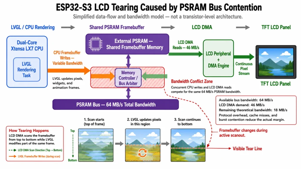
The Tearing Problem — Why Large Panels Expose PSRAM Bandwidth Limits
Direct answer — Calculate pixel traffic, then measure effective PSRAM/flash/EDMA and CPU behavior under the real workload. Tearing disappears only when buffer ownership and presentation are synchronized and every frame deadline is met.
Related Kadi Display reference: Kadi Display’s ESP32-S3 + GT911 + LVGL integration guide.
Screen tearing or drift can result from buffer ownership and synchronization errors, insufficient external-memory or EDMA service, pixel-clock settings, cache/flash interactions, or application load. Treat it as a system timing problem until measurements identify the bottleneck.
The display read traffic for an 800×480 RGB565 active image at 60 frames/s is 800 × 480 × 2 × 60 = 46.08 MB/s before blanking and implementation effects. That number is useful, but it does not prove available PSRAM headroom.
800 × 480 × 2 bytes × 60 fps = 46.08 MB/s (read bandwidth)
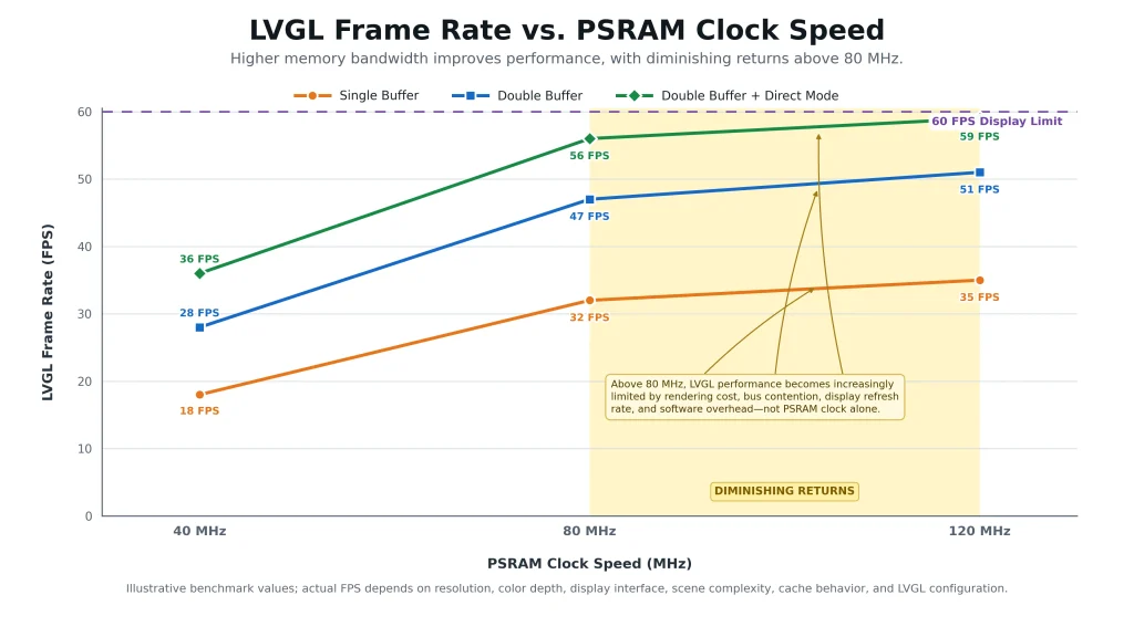
Do not convert the PSRAM clock into one universal usable MB/s figure. Bus mode, DDR/SDR operation, arbitration, cache behavior, flash sharing, EDMA access, CPU copies, alignment, and the board’s memory device determine effective bandwidth. Measure the exact firmware and hardware.
This guide presents the three-layer solution that production ESP32-S3 HMI products use to eliminate tearing: correct PSRAM configuration, double-buffer architecture with VSYNC synchronization, and LVGL rendering optimization.
PSRAM Configuration — The Foundation That Determines Maximum Bandwidth
Configuration discipline — Use Kconfig names and behavior from the exact ESP-IDF release. A flag that helps cache availability can also shift traffic to external memory; profile rather than assume.
The ESP32-S3 supports external PSRAM via either Quad SPI (4 data lines) or Octal SPI (8 data lines). For any RGB display larger than 3.5 inches, Octal PSRAM at 80 MHz is the minimum viable configuration.
Critical sdkconfig entries for Octal PSRAM at 80 MHz:
Options that place executable or read-only content in PSRAM can help specific flash/cache interactions and are recommended by Espressif for some bounce-buffer cases, but they also change external-memory traffic. Use the options documented for the selected ESP-IDF release and profile the complete workload.
Frame Buffer Architecture — Single vs. Double vs. Triple Buffering
The buffer allocation strategy determines whether screen tearing is architecturally possible or architecturally prevented. This is not a performance optimization — it is an architectural decision.
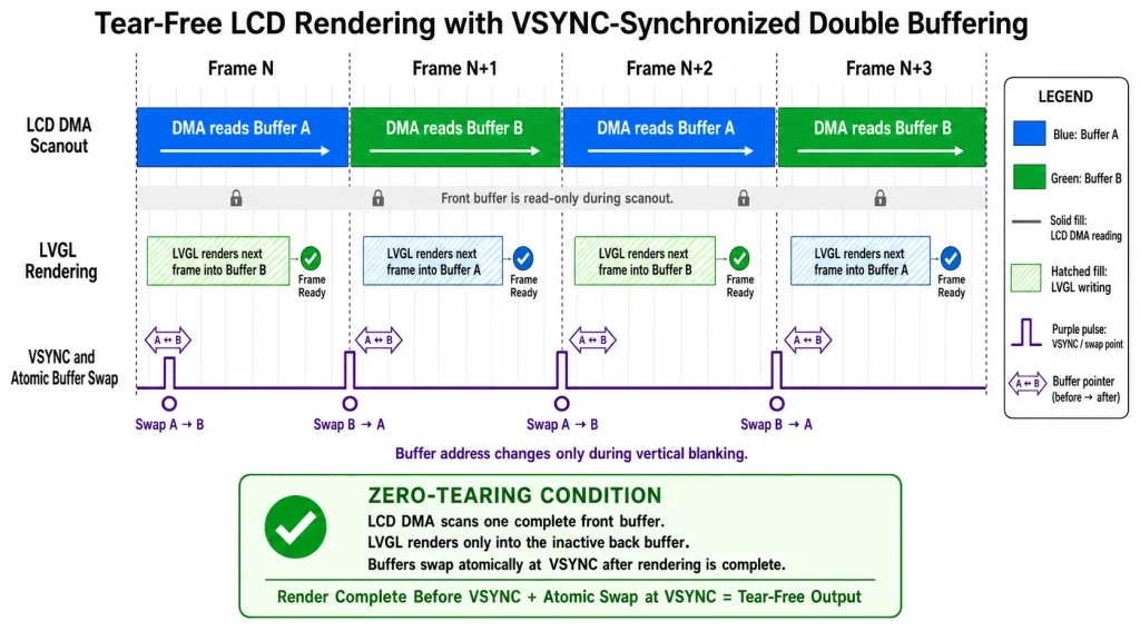
Double frame buffers with synchronized ownership are one robust architecture. ESP-IDF can allocate two screen-sized frame buffers with num_fbs = 2 or the equivalent flag, but the application and LVGL port must still coordinate rendering, flush completion, and frame presentation correctly.
Implementation in esp_lcd_rgb_panel API:
Register RGB panel event callbacks with the user context required by the selected ESP-IDF API, then keep interrupt work bounded. Do not copy a callback example without verifying the function signature and buffer-swap behavior for the exact framework version.
Bounce Buffer — The Alternative for PSRAM Bandwidth-Limited Scenarios
When PSRAM bandwidth is genuinely insufficient for double buffering (typically on boards with Quad SPI PSRAM or when running at reduced clock), the bounce buffer approach provides a partial solution.
Configuration for bounce buffer mode:
Bounce-buffer mode uses two internal-memory line buffers while data is copied from a PSRAM framebuffer. It can tolerate short bandwidth spikes and support higher pixel clocks, but increases CPU use, depends on cache availability, and can still flicker if memory copies miss DMA deadlines.
LVGL Configuration for ESP32-S3 — Direct Mode and Partial Refresh
Version gate — LVGL 9 uses LV_DISPLAY_RENDER_MODE_PARTIAL, DIRECT, and FULL concepts. Do not mix LVGL 8 direct_mode fields with LVGL 9 APIs in the same example.
Related Kadi Display reference: Kadi Display’s 24/7 GT911 + LVGL stability guide.
LVGL’s rendering pipeline must be configured to work with the ESP32-S3’s buffer architecture rather than fighting against it.
In LVGL 9, DIRECT and FULL render modes require display-sized buffers. With two buffers, the flush path can update the hardware framebuffer address, but buffer synchronization and flush completion must follow the LVGL display-port contract. PARTIAL mode uses smaller draw buffers and copy/flush work instead.
Pixel Clock Selection — Balancing Refresh Rate Against Bandwidth Headroom
The ESP32-S3 RGB LCD peripheral’s pixel clock (PCLK) directly determines both the display refresh rate and the PSRAM bandwidth consumed by LCD DMA.
Reducing refresh rate lowers continuous pixel traffic, but there is no universal 40 fps sweet spot and the visual result depends on UI motion and user expectations. Derive PCLK from complete panel timing and validate it within the panel’s allowed range.
PCLK configuration in code:
DMA Priority and Bus Arbitration — Preventing Starvation
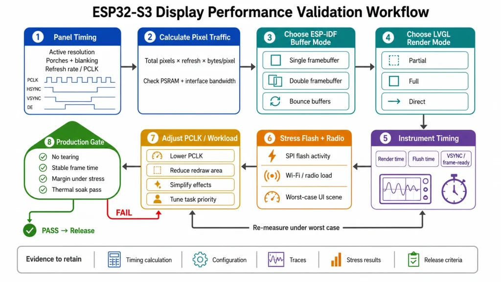
Production gate — Pass cold boot, Wi-Fi/BLE activity, filesystem writes, OTA path, maximum UI animation, touch load, and long soak without display drift, missed flush completion, watchdog symptoms, or silent recovery loops.
Related Kadi Display reference: Kadi Display’s common GT911/LVGL problems guide.
Even with correct PSRAM speed and buffer architecture, the ESP32-S3’s internal bus arbiter can cause intermittent tearing if DMA priority and task scheduling are not configured correctly.
Do not raise the watchdog timeout as the first response to display load. Keep VSYNC/ISR work short, move heavy rendering or copies to appropriate task context, measure worst-case latency, and fix starvation or priority inversion before changing watchdog policy.
Instrument the display port. Record PCLK, VSYNC period, LVGL render duration, flush duration, missed deadlines, recovery counts, PSRAM allocation, and high-water marks. Without telemetry, a system that “looks smoother” may still have rare starvation events.
Treat cache-disabled flash operations as a design scenario, not a surprise. Espressif documents that some bounce-buffer configurations depend on the external-memory cache and can fail during operations that disable it; the selected ESP-IDF feature set and OTA behavior must be tested together.
Keep examples versioned. Store ESP-IDF, LVGL, board revision, PSRAM mode, sdkconfig, panel timing, and driver commit with performance results so later library upgrades do not silently change buffer semantics.
Calculate memory before choosing a render mode. One 800×480 RGB565 framebuffer uses 768,000 bytes; two use 1,536,000 bytes before alignment and allocator overhead. Add LVGL draw buffers, image assets, decompression workspaces, network buffers, and application data. A design that barely allocates at boot can still fragment or fail after hours of use.
Measure pixel traffic with complete timing. The LCD peripheral outputs active pixels plus porch and sync periods according to the panel timing, and the memory/DMA implementation determines how data is fetched. Use the active-frame formula as a lower bound, then profile real EDMA and CPU behavior at the programmed PCLK.
Choose buffer ownership explicitly. With one full framebuffer, rendering can modify pixels while the LCD scans them unless updates are synchronized or limited. With two framebuffers, one can be displayed while the other is rendered, but the swap must occur only when both LVGL and the panel driver agree that the target buffer is ready.
Bounce-buffer sizing is a deadline trade-off. Larger line buffers tolerate longer PSRAM service interruptions but consume scarce internal memory and take longer to refill. Start from the ESP-IDF example, then vary size while measuring CPU load, ISR latency, drift, and flash/cache events rather than selecting ten lines as a universal value.
LVGL PARTIAL mode can be efficient for screens with small changed regions, but frequent overlapping invalidations, transparency, shadows, and full-screen animation can erase that advantage. Use LVGL performance metrics and application traces to identify what is actually redrawn. Simplify the UI before adding memory bandwidth solely to support decorative effects.
DIRECT and FULL modes need display-sized buffers in LVGL 9. DIRECT preserves a complete image and updates changed areas, while FULL redraws the screen. With two buffers, the display port can present the completed buffer, but it still must call the documented ready/synchronization functions at the correct time.
Keep the VSYNC callback small. Signal a task or synchronization primitive and return quickly; do not render widgets, perform long copies, log extensively, or access blocking services from interrupt context. Measure worst-case interrupt latency while Wi-Fi, storage, touch, and other DMA peripherals are active.
Stress the flash path. Run NVS writes, filesystem activity, firmware download, and the actual OTA sequence while the LCD is active. Verify whether the chosen buffer mode depends on cache availability and whether PSRAM XIP options are enabled as documented. A production update screen must remain deterministic, not merely attractive in a lab demo.
Optimize PCLK last. First fix incorrect buffer ownership, excessive copies, and GUI workload. Then lower or raise PCLK only within an allowed panel timing set and remeasure. A lower refresh rate can create useful margin, but it can also change touch perception, animation quality, and panel-controller behavior.
Evidence Package and Release Control
Before releasing a esp32-s3 rgb lcd and lvgl design, convert the article’s guidance into a requirements matrix. Give every requirement an owner, source, revision, unit, tolerance, verification method, sample quantity, and acceptance rule. This prevents an informative article from being mistaken for a product specification and makes unanswered questions visible while changes are still inexpensive.
Separate documented limits from planning assumptions. A datasheet value, vendor application note, calculated estimate, measured prototype result, and internal design target do not have the same authority. Label each one. When a value is only representative, record the condition that would make it change and identify the exact document or test that must replace it before production release.
Use production-intent samples for the final decision. Evaluation boards, hand-selected cables, open-bench wiring, laboratory power supplies, and debug firmware can hide tolerance and assembly problems. Repeat the relevant checks with approved component alternatives, final connector and flex routing, enclosure constraints, released clock and power settings, and the intended manufacturing process.
Define failure evidence before testing. Decide which measurements, logs, images, waveforms, error counters, and sample identifiers will be collected when a unit fails. If the team records only pass/fail, intermittent or environment-dependent behavior becomes difficult to reproduce. Good failure evidence should distinguish component, interconnect, firmware, assembly, and system-level causes without immediately blaming the most visible part.
Control changes after approval. A supplier substitution, firmware update, timing adjustment, coating change, connector revision, PCB stack-up change, or new assembly site can invalidate earlier evidence. The change process should state which reviews and tests repeat, who approves deviations, how old and new lots remain traceable, and what field or incoming data will be monitored after release.
For publication, keep ESP32-S3 RGB display terminology consistent with the engineering record. Do not turn a conditional finding into a universal rule to make the prose sound decisive. Search engines and answer systems reward clear direct answers, but technical credibility depends on preserving scope, units, test conditions, and uncertainty. A qualified answer is more useful than a confident number that belongs to another component.
Complete the review with an independent reader. Ask someone who did not write the article or perform the first test to reproduce one calculation, locate each cited requirement, and challenge the main conclusion. Close any gap between the published guidance and the controlled engineering documents. This simple review often catches unit mistakes, stale revisions, hidden assumptions, and claims that cannot be verified from the evidence provided.
Archive the released package in a location shared by engineering, quality, procurement, and support. Include the article revision, approved drawings, links, calculations, test records, known limitations, and decision owner. That package gives later teams enough context to investigate a field issue or approve a controlled change without rebuilding the original reasoning.
FAQ: ESP32-S3 RGB LCD and LVGL Optimization
Is 80 MHz Octal PSRAM always enough for 800×480?
No. Effective service depends on memory mode, arbitration, cache/flash activity, copies, pixel clock, and workload. Measure the exact system.
Does double buffering automatically remove tearing?
Only when the display reads one stable buffer while rendering targets another and the presentation/swap is synchronized correctly.
When should bounce buffers be used?
They are useful when internal line buffers can protect DMA from short PSRAM bandwidth spikes, but they increase CPU/cache dependency and need deadline validation.
Which LVGL mode fits two hardware framebuffers?
In LVGL 9, DIRECT or FULL can use display-sized buffers. The port must implement the documented flush and synchronization behavior.
Should I increase the watchdog timeout?
Not before measuring and fixing long ISR work, starvation, blocking copies, or task-priority problems. Watchdog policy is the last step, not the first optimization.
Engineering source notes
Related Kadi Display reference: ESP32-S3, GT911, and LVGL integration.
Related Kadi Display reference: common GT911 and LVGL troubleshooting.
Related Kadi Display reference: 24/7 GT911 + LVGL touchscreen stability.
Primary technical references: ESP-IDF 5.5 RGB LCD documentation; Espressif LCD FAQ; LVGL current display setup documentation.
Product Reference & Engineering Support — For industrial TFT LCD modules, interface documentation, application review, sample validation, and OEM/ODM support, contact Sales@sz-kadi.com or review the Kadi Display product range.
Product range: industrial TFT LCD modules and custom display solutions.
Code and configuration concepts are version-sensitive. Verify Kconfig symbols, structure fields, callbacks, render modes, cache behavior, and timing against the exact ESP-IDF, LVGL, board, PSRAM, and panel versions. Measure production-intent workloads before release.
PREVIDENTE
Optical Bonding vs Air Bonding for Industrial Touchscreens: Cost, Durability & Performance
Prossimo
MIPI DSI Bandwidth Guide: Lanes, Pixel Clock, and Data Rate per Lane
Lascia un commento

Ultimi Blog & Notizie
- MIPI DSI Display Driver Development for Embedded Linux What Hardware Buyers Need to Confirm
- IP65 vs IP67 Industrial Displays: What the Rating Actually Covers
- How to Specify a Touchscreen for Food-Processing Equipment
- Thermal Management for High Brightness LCDs in Sealed Outdoor Enclosures
- 4 Wire vs 5 Wire Resistive Touchscreens for Industrial Equipment
Blog & Notizie correlate
-
 TN contro IPS2024-7-9
 -
TN contro IPS2024-7-9

