




Casa
-
Blog & Notizie
-
How to Choose an LCD Controller Board: Architecture, EDID, Timing and Latency
How to Choose an LCD Controller Board: Architecture, EDID, Timing and Latency
2026-09-17
11:39
SOURCE → PROCESSING → PANEL
How to Choose an LCD Controller Board: Architecture, EDID, Timing and Latency
READER DECISION Board architecture and exact configuration
Choose the Right Architecture Before a Board
DECISION Use a native host-to-panel link when the host already supports the exact panel contract. Use a protocol bridge only when direction, roles, timing and pixel format can pass without full image processing. Choose a scaler/controller board when external source modes must be accepted, advertised through EDID, scaled or otherwise processed before the panel is driven. Choose a complete monitor assembly when the project wants a standard equipment-level input and integrated mechanics, power and service responsibility.
Start With the Architecture, Not the Board Catalog
The lowest-risk design uses a native host output that the panel and operating system already support. Add a controller board when the source and panel do not share an interface, when the source must accept standard external video modes, or when the system needs scaling, OSD, rotation, color processing, multiple inputs, or a managed backlight path.
KadiDisplay’s guide to connecting a custom TFT to a controller or ProAV system helps clarify whether the requirement is for a raw panel path, an adapter/bridge, or a complete input-ready display. Do this classification before comparing connector photographs.
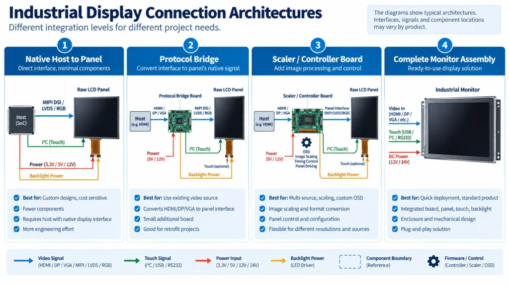
Match Three Independent Contracts
Controller-board compatibility is the intersection of the source input, processing behavior and panel output—not a resolution match.
Match Three Contracts End to End
Contract 1: source to controller input
List every source that must work: PC, SBC, camera, media player, switcher, embedded GPU, or other equipment. For each source, record the physical interface, expected modes, pixel format, color range, refresh behavior, audio or protected-content requirements if relevant, hot-plug behavior, and cable constraints.
“HDMI input” is incomplete. The controller may accept only selected timings, color formats, or clock ranges. It may expose an EDID with a preferred mode that the source honors, ignores, or cannot generate. Source devices can also behave differently after standby, cable reconnect, resolution change, or brownout recovery.
Contract 2: processing inside the board
Determine whether the board passes pixels, buffers lines, or stores frames. Ask which operations are active for each mode: scaling, cropping, aspect-ratio conversion, frame-rate conversion, deinterlacing, rotation, dithering, color-space conversion, limited/full range handling, overscan, OSD, or image enhancement. These functions affect latency, picture quality, memory bandwidth, startup behavior, and test coverage.
Do not accept one generic latency number. A line-buffer path may behave differently from a frame-buffer path, and the firmware may choose another pipeline when scaling, deinterlacing, rotation, or OSD is enabled. Request the measurement method and test the actual source mode, panel mode, and feature state.
Contract 3: controller to panel
Name the panel output protocol and role, lane/channel count, rate or pixel-clock range, timing limits, color depth and mapping, voltage domains, connector and cable, initialization, power sequence, and backlight control. Panel interface families contain many incompatible implementations.
Il industrial display interface selection guide provides a system-level comparison of LVDS, MIPI DSI, eDP, HDMI, and related architectures. Use it to confirm that the controller output is appropriate for the panel rather than assuming a board can translate any input to any display.
Keep EDID Separate From Panel Timing
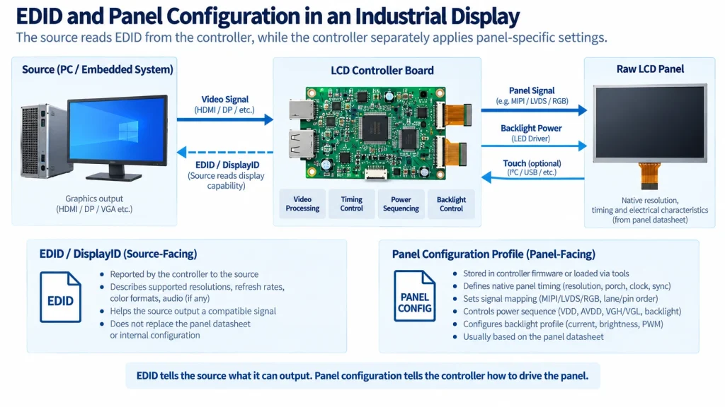
EDID controls what the source sees, while a separate panel profile controls what the raw display receives.
EDID Describes Source-Facing Capabilities, Not the Raw Panel Contract
EDID or DisplayID helps the source identify the display and choose modes. It can include a preferred timing, physical size, model information, color data, and other capabilities. The raw panel, however, still requires its own native timing, interface mapping, power sequence, and backlight behavior. A controller board sits between those two descriptions.
A correct EDID does not prove that the panel output profile is correct. Conversely, a correct panel timing does not guarantee that the source will choose it. Freeze both the source-facing descriptor and the panel-facing configuration, then test how the board handles unsupported or alternate source modes.
Microsoft’s display guidance notes that the operating system depends on accurate descriptor data for native resolution, physical size, model identity, and other display properties. Treat the descriptor as a controlled binary, not a label that can be copied from a similar monitor.
Eliminate Boards With Missing Functions
A board remains a candidate until every required processing, power, backlight, touch and service function has an owner.
Use a Selection Matrix That Exposes Missing Functions
The following fields should be completed for each candidate board. A blank is an engineering risk, not a neutral score.
When evaluating available options, the KadiDisplay controller boards and integration accessories category can provide concrete board-level candidates. Retain only products whose published input, output, panel, power, backlight, touch, and environment information matches the project; verify the ordered revision and firmware in the quotation.
Treat Power, Backlight, Touch, and Interconnect as Separate Subsystems
Controller boards often combine functions, but the design review should not. Build a rail-and-sequence table for source, board, bridge/scaler, panel, backlight, and touch. Include nominal and tolerance ranges, startup current, inrush, ramp, reset, enable, shutdown, discharge, and back-power paths. Test cold start, warm restart, brownout, repeated cycling, and abnormal source connection in the intended configuration.
For the backlight, confirm string count, forward-voltage range, current, driver compliance and protection, connector rating, dimming method, enable/PWM polarity, minimum brightness, startup behavior, thermal path, and whether brightness control comes from keys, OSD, DDC/CI, a host signal, or another interface. A bright image on one sample does not establish driver margin or lifetime.
Touch normally has a separate data path. Specify the controller, interface, address if relevant, reset/interrupt, power, USB enumeration or platform driver, firmware, coordinate transform, cover/bonding stack, grounding, and cable route. A USB-C connector may carry touch, power, video, or only a subset; verify the exact implementation.
Connector and cable design also belongs to the released configuration. Review the MIPI, LVDS, RGB, and touch FPC connector guide when the board-to-panel path uses a flex or fine-pitch connector. Same pitch and pin count do not prove mapping, current capacity, signal integrity, or mechanical retention.
Domande frequenti
These questions isolate four boundaries that are easy to miss when a board is advertised mainly by connector and resolution.
Does an HDMI LCD controller board work with any panel of the same resolution?
No. Input resolution is only one boundary. The board also needs the panel’s output protocol, lanes/channels, timing, mapping, voltage, connector, initialization, power sequence, backlight path, firmware profile, and mechanical interface. Confirm the exact panel part and revision.
What is the difference between EDID and native panel timing?
EDID describes capabilities to the video source and influences the mode it selects. Native panel timing defines the pixel stream that the raw panel must receive. A scaler/controller may accept one timing from the source and generate another for the panel.
Does scaling always add one frame of latency?
No universal value applies. Delay depends on whether the design uses line or frame buffering and which processing features are active. Ask for the architecture and measure the actual input mode, output mode, firmware, scaling, rotation, deinterlacing, and OSD state.
Can the controller board power touch through the video cable?
Only if the exact board and connector define that function. HDMI does not automatically carry touch. Many systems use USB for touch and a separate power input; others integrate selected functions through USB-C or a custom harness. Verify power capacity, data role, grounding, enumeration, and cable pinout.
Validate and Freeze the Named Configuration
Selection is complete only when the exact firmware, EDID, panel profile, cables and feature state can be reproduced and recovered.
Validate the Named Configuration, Not the Marketing Description
Use representative sources, modes, content, cables, temperatures, boot orders, standby cycles, and fault recoveries. Run tests with scaling both enabled and disabled where possible. Check geometry, pixel mapping, gradients, small text, motion, black/white levels, color range, aspect behavior, startup time, latency-sensitive interaction, and camera compatibility if relevant.
Freeze the accepted state as an integrated package. Include board and panel part numbers, revision, firmware, EDID, panel profile, cables, power supply, backlight settings, touch configuration, source-mode list, mechanical stack, test limits, and recovery procedure. A controller board that works only after an engineer manually selects hidden settings is not ready for production.
Write a Production Configuration Specification
Controller-board selection is incomplete until the working bench state can be reproduced without the original engineer. Convert the validated setup into a short controlled specification that procurement, manufacturing, service, and the board supplier can all identify.
Define how a blank replacement board obtains the approved state. If programming happens at the supplier, specify the identity and verification evidence returned with each lot. If programming happens in production, control the executable, configuration file, fixture, access rights, logs and failure recovery. A service menu that can change panel voltage, mapping or timing should have a controlled procedure and, where practical, restricted access.
Measure latency only when the application needs a limit. Name the source mode, panel mode, scaling, rotation, deinterlacing, OSD and other processing features; distinguish input-to-photon from electrical or software-only measurements; report distribution and test uncertainty rather than one unexplained number. Recheck the states users can actually select.
Plan failure recovery as part of the configuration. Test corrupted or interrupted updates where safely supported, invalid source modes, panel disconnect/reconnect only under permitted conditions, brownout, watchdog reset, standby, repeated boot and default restoration. Define which settings survive power loss and how production or service can prove the correct panel profile afterward.
Finally, tie supplier change notices to the released package. A different scaler IC, memory, oscillator, firmware, connector or backlight component can alter compatibility even if the sales model is unchanged. Require revision traceability and define which changes trigger review, samples, regression or requalification.
For long-lived equipment, retain the tools needed to recover the state: firmware image, configuration utility, supported operating-system version, programming cable, credentials ownership and a documented replacement-board procedure. Confirm whether the supplier can reproduce the approved revision or will substitute a successor. A lifecycle plan should name the evidence required to qualify that successor, not merely request advance notice.
Include one archived, verified recovery kit and periodically prove that it still programs a controlled spare board.
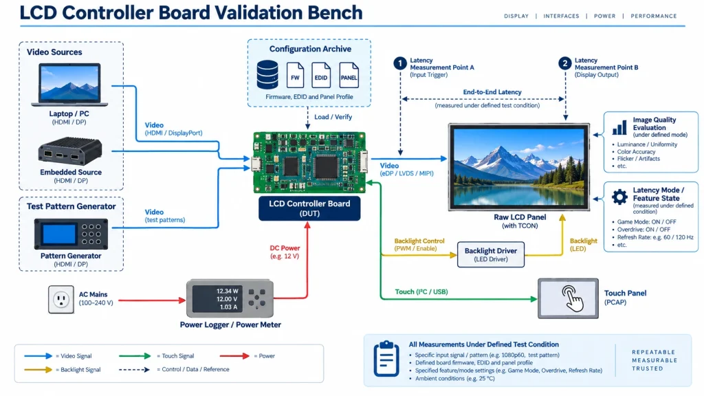
RELEASE GATE Validate every required source, mode and boot order with the exact board, panel, firmware/profile, EDID, cables, supply, backlight and touch configuration. Check image geometry, color/range, motion, latency where it has a requirement, startup/shutdown, thermal state, brownout and recovery. Release the setup only when procurement and production can reproduce it from the archived package without hidden service-menu knowledge.
For a board review, send KadiDisplay the source list, accepted modes, exact panel/revision, interface and timing, processing requirements, latency definition, power/backlight/touch details, cable constraints and lifecycle needs via the engineering contact page.
Primary Sources
- Microsoft display-device and descriptor guidance
- Linux DRM/KMS helpers documentation
- Texas Instruments display-interface bridge selection guide
ENGINEERING DISCLAIMER Board labels, connector names, and a displayed image are not compatibility approval. Selection applies only to the named source mode, controller hardware revision, firmware and EDID, panel profile, cable, touch path, backlight circuit, and feature state that were reviewed. Reconcile the exact panel rails, pinout, timing, mapping, sequence, and illumination limits before power-up, then measure the final configuration for image behavior, latency, recovery, temperature, and required source modes. Protected-content support, licenses, availability, and customization scope require separate written confirmation.
PREVIDENTE
Non più
Prossimo
Industrial Display RFQ Checklist: Build a Supplier-Ready Evidence Package
Lascia un commento

Ultimi Blog & Notizie
- How to Choose an LCD Controller Board: Architecture, EDID, Timing and Latency
- Industrial Display RFQ Checklist: Build a Supplier-Ready Evidence Package
- Industrial LCD Drop-In Replacement Checklist: From Hard Stops to Release Evidence
- MIPI DSI in Industrial LCD Displays: What Engineers Should Know
- MIPI DSI vs LVDS vs RGB vs eDP: Which Interface Is Best for Industrial Displays?
Blog & Notizie correlate
-
 TN contro IPS2024-7-9
 -
TN contro IPS2024-7-9

