




eDP LCD Panel Integration: Power, AUX, Link Training, Video and Backlight
2026-09-19
10:19
eDP LCD Panel Integration: Power, AUX, Link Training, Video and Backlight
ORDER Power → AUX/HPD → training → video → backlight
Do Not Start Until Five Subsystems Are Defined
STOP / SAFETY GATE Do not connect or power an eDP panel until five subsystems are separately defined: panel logic power and sequence; HPD/AUX control; main-link lane count and rate; video timing and pixel format; and backlight power/enable/dimming. Verify the exact connector, pinout, voltage domains and polarity. Do not assume hot-plug support. LED boost outputs may be hazardous to probe or short even when the system input voltage is low.
Treat eDP as Five Related Subsystems
Embedded DisplayPort uses DisplayPort concepts for an internal display connection, but the main link is only one part of the design. Separate the path into five subsystems so that one success does not mask a failure elsewhere.
Touch is normally a separate subsystem unless the exact assembly and interface define otherwise. Record its USB, I²C, HID-over-I²C, power, reset, interrupt, grounding, firmware, and cable requirements independently.
VESA’s public eDP 1.5 announcement and DisplayPort overview establish standards context, while implementation details remain in the applicable standard and endpoint documentation. KadiDisplay’s industrial display interface guide helps compare eDP with LVDS, MIPI DSI, HDMI, and USB at system level.
Establish Stop Conditions Before Applying Power
Do not begin software debugging until the hardware identity is controlled. Record the source board and revision, processor or bridge, panel full part/revision, connector drawings, cable drawing and orientation, lane/polarity configuration, power rails, backlight driver, firmware/BIOS/kernel/driver versions, and approved schematic. Inspect the mating connector, contact side, keying, pin numbering, cable fold, shield/ground contacts, and panel mechanical installation.
Stop if the panel voltage is unknown; source and panel pinouts have not been reconciled pin by pin; AUX or HPD electrical levels are unclear; the cable is not traceable; a required rail exceeds its range; backlight power is being confused with panel logic power; or the power sequence cannot be enforced. A black panel is preferable to damaged hardware.
If the source begins with HDMI or another external format, define the controller/bridge architecture before this playbook. The custom TFT-to-controller and ProAV guide clarifies where a scaler/controller or directional bridge belongs.
Match Source and Panel Capabilities on Paper
Build a capability handshake rather than selecting one attractive lane/rate combination. Start from the modes the product needs, then find a supported intersection between source and panel.
Lane count alone does not define resolution. Capacity depends on link rate, coding, color depth, timing totals and features. Calculate from the exact mode and standard revision. Do not assume that a source advertising a maximum link rate can provide it on every board route, firmware version, lane count, or power state.
Preserve the raw DPCD and EDID/DisplayID data read from the final panel, not only a software summary. Microsoft’s display-descriptor guidance describes how identity and native-mode information is exposed to Windows, but a descriptor does not replace the panel’s electrical, timing, sequencing, or mechanical specification.
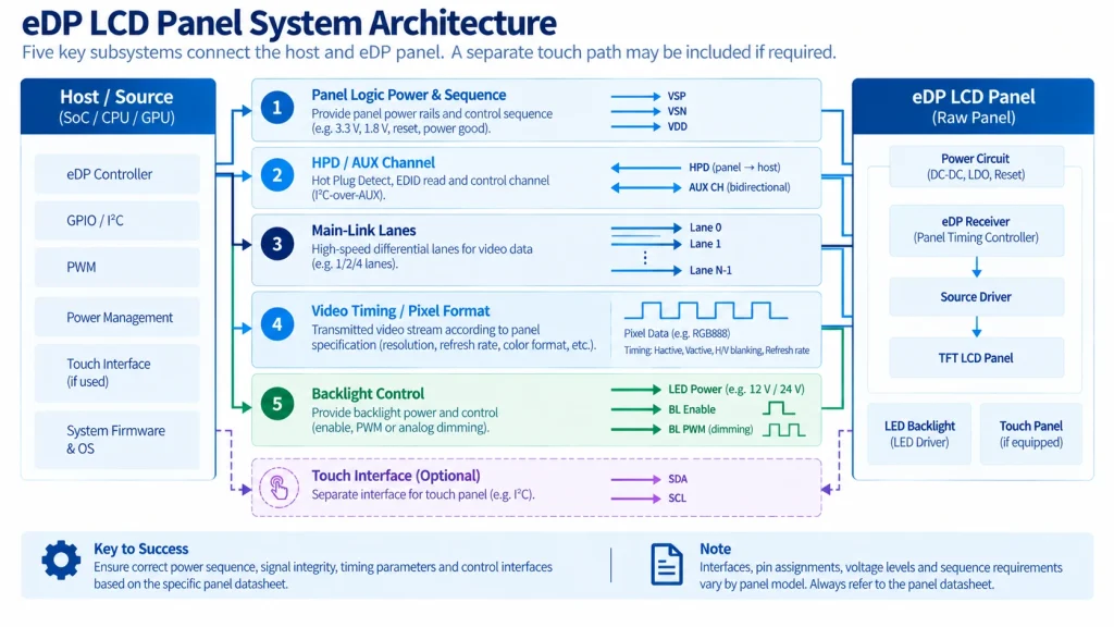
Bring Up Power, AUX, Link, Video and Backlight in Order
Power, HPD/AUX, main-link training, active video and backlight form a state-dependent sequence; each transition needs an observable checkpoint.
Design Power and Backlight as a State Machine
Panel power, link activity, video validity, and backlight illumination have ordering and delay constraints. Create explicit states such as off, panel rail ramp, reset/readiness, AUX/HPD available, discovery, training, video stable, backlight enabled, dimming, low-power, shutdown, fault, and recovery. Assign every transition to hardware, boot firmware, operating-system driver, embedded controller, GPIO, regulator, or backlight driver.
Intel’s public platform material shows panel-power and backlight timing as configurable parameters that vary by panel. Treat it as an example of platform implementation, not a universal eDP sequence. Use minimum and maximum limits from the exact panel and source/platform documents, then measure actual waveforms at qualified test points.
Bring Up One Observable Layer at a Time
- Power-off inspection — Confirm connector orientation, cable identity, ground references, lane and AUX routing, HPD path, backlight wiring, continuity where appropriate, and the absence of shorts on power rails.
- Controlled panel power — Apply panel logic power under the planned state machine. Measure rail amplitude, ramp, current, reset, and discharge behavior while the backlight remains disabled.
- HPD and AUX observation — Confirm the expected electrical levels and source event. Capture AUX transactions or errors with the diagnostics available on the actual platform.
- Capability readout — Save raw DPCD and EDID or DisplayID data. Compare identity, checksums, modes, and advertised link capabilities with the exact panel documentation.
- Lowest-risk link training — Request a supported lane and rate combination with margin. Use source and sink status to separate discovery failures from clock-recovery or channel-equalization problems.
- Deterministic native video — Enable a known native test pattern. Verify active timing, pixel format and depth, ordering, stability, and content before treating the main link as proven.
- Backlight enable and dimming — Enable illumination at a safe commanded level only after video is stable. Verify enable polarity, PWM or AUX method, specified operating range, brightness response, current, and thermal behavior.
- Expanded states and corners — Exercise every required mode, boot path, warm restart, suspend and resume, permitted cable state, voltage and temperature corner, brightness level, fault response, and recovery path.
Do not advance merely because the visible symptom changes. Preserve the evidence from each successful checkpoint so a later failure can be localized without restarting from assumptions.
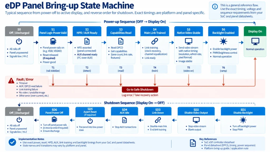
Record the First Missing Checkpoint
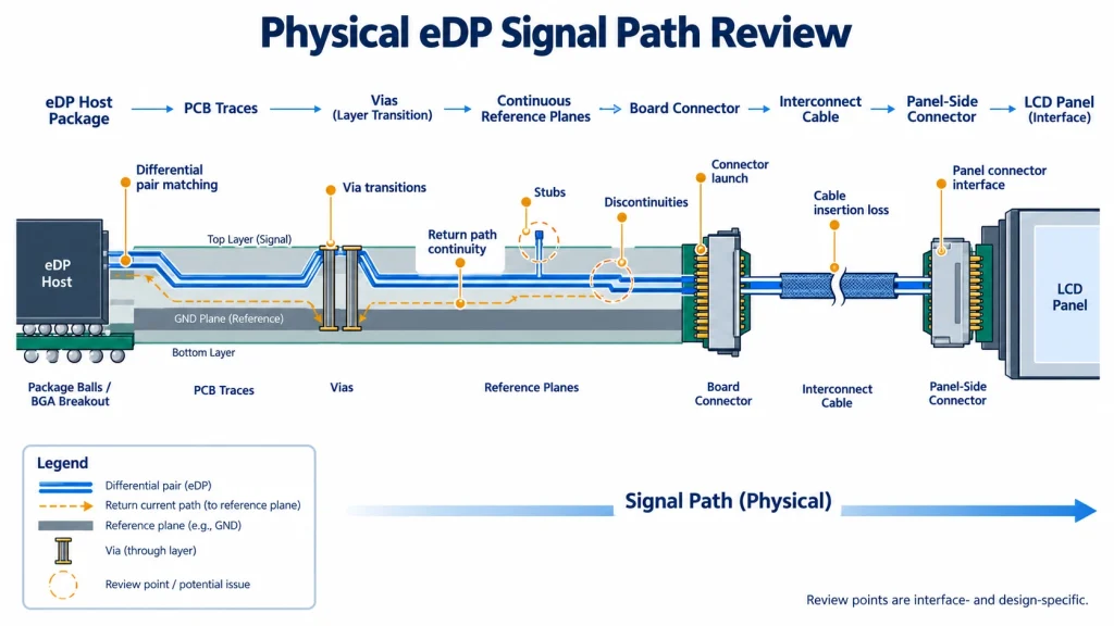
The final board and cable must preserve power and signal integrity from the host package through every connector and return path.
Protect Signal Integrity From Source Ball to Panel Connector
Use the source/platform and connector/cable rules for controlled impedance, intra-/inter-pair skew, insertion loss, return loss, crosstalk, reference planes, via transitions, AC coupling where required, and lane polarity or reversal support. Route AUX according to its electrical requirements rather than treating it as another main-link lane. Keep high-current backlight switching and noisy power loops away from sensitive routes and preserve return paths through connectors and cable shields/grounds.
The final cable is part of the channel. Record its conductor/pair construction, shield and drain connections, length, connector contacts, ground pins, fold/bend radius, assembly stress and lot identity. The FPC and connector design guide provides a broader interconnect checklist. Development adapters from the tools and accessories category can accelerate proof-of-concept, but exact pinout, lane routing, rates and panel compatibility must be confirmed.
For difficult links, inspect at permitted test points with appropriate tools and vendor guidance. Do not attach probes or fixtures that invalidate the channel and then treat the altered result as production performance. Retain source/link status, error counts where exposed, cable and board identity, environmental state, and test setup.
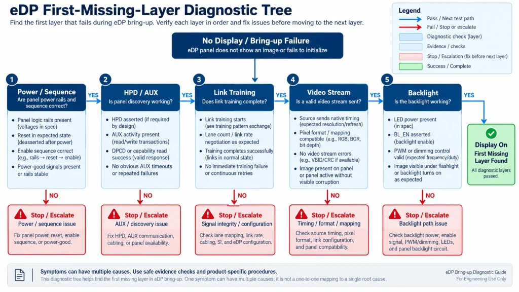
Branch From the Missing Layer, Not the Visible Symptom
Troubleshooting should start at the first missing layer rather than from the visible black-screen symptom.
Diagnose by the First Missing Layer
A symptom name is not a root cause. Find the earliest layer that lacks evidence and avoid changing multiple variables at once.
TI’s link-training material is useful for understanding the roles of the main link, AUX and HPD during training. Platform logs and Linux DRM/KMS connector/link status can add evidence, but software messages must be correlated with physical measurements and the actual device implementation.
Domande frequenti
These answers clarify capability and symptom boundaries that remain useful beside the ordered bring-up path.
How many lanes does an eDP LCD panel need?
Use a lane count and link rate supported by both endpoints with capacity for the exact timing, color depth and coding. Resolution alone does not determine the answer, and more lanes are not automatically better if the configuration is unsupported.
Can link training pass while the screen remains black?
Yes. The pixel stream can be absent, black, incorrectly timed or formatted; the panel may be in the wrong state; or the backlight may be disabled or faulty. Verify deterministic video and illumination separately.
Is eDP backlight brightness always controlled over AUX?
No. Implementations may use AUX-based controls, PWM, enable signals, or a platform-specific combination. Follow the exact source, panel and backlight-driver documentation.
Release the Sequence and Recovery Behavior
A stable first image is only the beginning; boot, resume, brownout, recovery and configuration identity must be released together.
Lock Software, Recovery, and Production Evidence
Freeze BIOS/firmware, kernel/driver, device tree or ACPI data, panel descriptor/quirk, power-sequence parameters, lane/rate policy, backlight method, and bridge configuration if present. Test cold boot, reboot, display-off/on, suspend/resume, low-power entry/exit, brightness changes, source reset, panel power interruption, and fault recovery. Define safe fallback: it should not repeatedly overstress the panel or flash the backlight while retrying.
Production release should include controlled schematics and cable drawings, approved panel/revision, software manifest, raw capability reference, power/sequence measurements, native-mode and pattern results, SI/EMC evidence appropriate to the product, environmental and reliability evidence, assembly instructions, incoming identity checks, programming method, end-of-line test, pilot data, known limitations, and supplier change/lifecycle controls.
Use the same observability in production that made engineering bring-up successful. An end-of-line test should prove panel identity where the design exposes it, expected HPD/AUX behavior, a legal trained link, deterministic image content, backlight control and recovery from the states manufacturing can encounter. Preserve enough software and fixture identity to distinguish a product fault from a test-station change.
Define diagnostic counters and logs before a field problem occurs. Useful evidence may include requested and negotiated lane/rate, training stage/status, DPCD snapshots, descriptor checksum/identity, connector link status, mode timing, power-state transitions, backlight command and driver faults. Do not log sensitive or excessive data by default; select bounded information that can answer the product’s likely failure questions.
If the platform applies panel-specific quirks, table entries or sequence overrides, make the selection deterministic. State whether it uses EDID/DisplayID identity, board SKU, panel cable option, firmware configuration or a fixed BOM relationship. Define behavior for unknown or unreadable identity so the fallback does not energize an incompatible panel configuration.
Document which diagnostics remain available in a release build and how service retrieves them without changing link state. A reproducible snapshot is more useful than an uncontrolled “retry until it works” procedure.
RELEASE GATE Release only after cold/warm boot, repeated cycling, suspend/resume, brownout recovery and permitted connect/disconnect cases work on the final host, cable, panel, firmware and backlight configuration. Archive the rail/sequence record, achieved link settings, native timing, software versions, cable/BOM identity, logs, acceptance limits and recovery procedure. Regress after any board, cable, enclosure, grounding, timing or firmware change.
KadiDisplay can review panel, cable and controller integration via the engineering contact page; send the exact host, panel/revision, lane/rate capability, timing, connector/pinout, cable, power sequence and backlight requirements.
Primary Sources
- VESA announcement for Embedded DisplayPort Standard Version 1.5
- Linux DRM/KMS documentation
- Microsoft display-device design guidance
- Intel example of panel power sequencing and backlight control
ENGINEERING DISCLAIMER The sequence in this playbook is an observability framework, not a universal eDP timing specification, connector pinout, link-training implementation, or panel initialization profile. Use the exact platform, panel, connector, cable, backlight, and applicable VESA documentation. Keep illumination disabled until valid video is established, and stop before power-up, connect/disconnect, or probing when rails, pin direction, discharge, AUX/HPD levels, sequence, or approved test points are uncertain. Validate every required boot, low-power, recovery, cable, voltage, and temperature state on the final assembly.
PREVIDENTE
LCD Prototype Passed but Pilot Units Fail: A Display Integration Isolation Workflow
Prossimo
How to Choose an LCD Controller Board: Architecture, EDID, Timing and Latency
Lascia un commento

Ultimi Blog & Notizie
- MIPI DSI Display Works at Room Temperature but Fails After Warm-Up: A Troubleshooting Workflow
- LCD Prototype Passed but Pilot Units Fail: A Display Integration Isolation Workflow
- eDP LCD Panel Integration: Power, AUX, Link Training, Video and Backlight
- How to Choose an LCD Controller Board: Architecture, EDID, Timing and Latency
- Industrial Display RFQ Checklist: Build a Supplier-Ready Evidence Package
Blog & Notizie correlate
-
 TN contro IPS2024-7-9
 -
TN contro IPS2024-7-9

