




15 Pin vs 22 Pin Raspberry Pi DSI Connectors Cable Pinout and Compatibility
2026-10-15
00:00

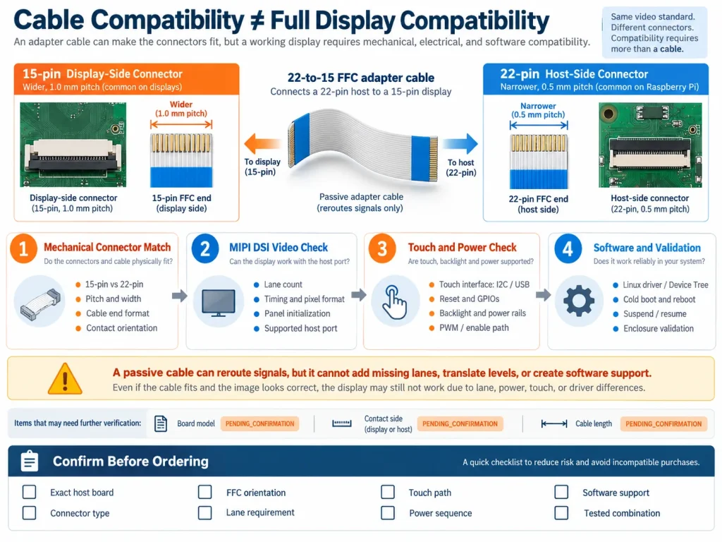
A 15-pin Raspberry Pi DSI connector and a 22-pin CAM/DISP connector are not interchangeable merely because both carry MIPI DSI. The connectors differ in pin count, pitch, width, cable format, and available signal positions. Raspberry Pi 4 and earlier boards generally use a 15-way display connector, while Raspberry Pi 5 uses smaller 22-way combined camera/display connectors. A purpose-built FFC can bridge the physical formats for a supported display, but it cannot make an unverified panel electrically or software compatible. For OEM buyers, the correct decision requires the exact Raspberry Pi model, cable, pin mapping, lane requirement, driver, power, touch path, and enclosure layout. Display Kadi reviews these items as part of a complete display integration rather than treating the cable as the whole interface.
The physical difference between 15 pin and 22 pin connectors
Raspberry Pi documentation identifies the older full-size display connector as a standard 15-pin connector with 1.0 mm pitch and about 16 mm width. Raspberry Pi 5 provides two mini 22-pin, 0.5 mm pitch, 11.5 mm wide CAM/DISP connectors. The smaller pitch saves board space, but it also requires a different FFC and tighter control of insertion, contact orientation, and bend radius. A 15-pin cable cannot be pushed into a 22-pin connector, and a generic 22-pin camera cable should not be assumed to carry the right display signals.
|
Articolo |
15-pin format |
22-pin format |
Buyer implication |
|
Connector |
15 contacts, 1.0 mm pitch |
22 contacts, 0.5 mm pitch |
Cable ends and ZIF connectors must match |
|
Typical host |
Raspberry Pi 4 and earlier with DSI |
Raspberry Pi 5 CAM/DISP ports and selected CMIO boards |
Record the exact board and revision |
|
Common cable |
15-way to 15-way |
22-way to 15-way or 22-way to 22-way |
Choose the cable for both host and display |
|
Signal capacity |
Common older display path |
Can expose more signal positions and, on supported hardware, additional DSI lanes |
Confirm lanes routed by the actual board |
Which Raspberry Pi boards use each connector
For the official 7-inch Touch Display and the 5-inch or 7-inch Touch Display 2, Raspberry Pi specifies a 15-way to 15-way FFC for Raspberry Pi 4 and earlier, and a 22-way to 15-way Standard-Mini FFC for Raspberry Pi 5. The 22-way end is the smaller end and connects to Raspberry Pi 5. The display end remains the wider 15-way format. The 10-inch Touch Display 2 instead uses a 22-way to 22-way Mini-Mini FFC and requires four DSI data lanes. This example shows why buyers must select a cable for the exact host-and-display pair rather than by screen size or the word DSI alone.
Compute Module IO boards also require model-specific review. The chosen DISP0 or DISP1 port must match the cable and software configuration. Raspberry Pi Zero models illustrate another purchasing trap: a small 22-pin camera connector does not provide a DSI display connection. Connector appearance does not establish interface function.
Why the pinout is more than a pin count
A reliable pinout comparison starts with the host schematic, connector drawing, cable drawing, and display-module specification. Map each DSI clock pair and data-lane pair, then map every ground, power, reset, enable, backlight, touch, identification, and no-connect position. Confirm pin 1, top- or bottom-contact orientation, same-side or opposite-side cable contacts, and the connector latch direction. Reversing an FFC or using the wrong contact style can leave the backlight on while the panel receives no valid image, or it can apply voltage to an unintended signal.
Do not build a universal 15-to-22 pin-number table from unrelated products. The Raspberry Pi Standard-Mini cable implements a defined system mapping for supported Raspberry Pi display connections. A third-party panel may place power, reset, touch, or backlight functions on different pins even when its connector has the same number of contacts. A passive adapter can reroute existing signals. It cannot add a missing lane, translate voltage levels, generate a panel reset sequence, or convert an unsupported display mode.
For a drawing-based review method, use Kadi’s MIPI DSI connector and FPC pinout checklist. It separates the mechanical connector, cable contact geometry, electrical mapping, and system functions that must be compared before power is applied.
Cable compatibility does not prove display compatibility
After the cable is confirmed, the MIPI DSI link still has to work at three additional levels. First, the host must expose the required number of data lanes and support the panel’s lane rate, pixel format, video or command mode, clock behavior, resolution, and complete timing. A 22-pin connector can provide positions for a wider signal set, but the board and selected port must actually route the lanes required by the display. The four-lane requirement of the 10-inch Touch Display 2 is a useful reminder that connector family and lane implementation are related but not identical specifications.
Second, Linux needs the correct host driver, panel initialization, Device Tree description, GPIO assignments, regulators, and backlight control. A custom panel may require its own driver or a verified modification. Third, test cold boot, warm reboot, suspend and resume, brightness, touch, thermal behavior, and enclosure operation. One successful bench boot is not production approval.
Kadi’s KD070RPI02 Raspberry Pi DSI touch display provides a concrete example: the published configuration is a 7-inch 1024 x 600 display with MIPI DSI video, I2C touch, and optical bonding. Its page also states that compatibility depends on the Raspberry Pi model, operating-system version, DSI connector and cable, display settings, touch configuration, and orientation. Those conditions should be confirmed for the purchased revision and system image.
Keep video touch and power as separate checks
A single FFC may carry several functions, but each path needs a separate check. MIPI DSI carries display video and control traffic. Capacitive touch commonly uses I2C, although some modules use USB. Power and backlight may come through the display assembly, GPIO wiring, or a separate board. A working image does not prove touch compatibility, and a lit backlight does not prove DSI initialization succeeded.
For touch, confirm the controller, bus voltage, I2C address where applicable, interrupt and reset GPIOs, driver, coordinate transformation, and screen orientation. For power, confirm every rail, current requirement, startup delay, reset polarity, backlight enable, and PWM level. If an adapter board is included, identify whether it only changes the FFC mapping or also provides regulation, level shifting, backlight drive, or other active functions.
A purchasing checklist for 15 pin and 22 pin projects
Before approving a cable or display BOM, ask the supplier to document:
– The exact Raspberry Pi or Compute Module, carrier board, board revision, operating system, kernel, and BSP image.
– The host connector reference, pin count, pitch, contact orientation, and whether the port is configured for camera or display use.
– The display part number and revision, connector drawing, pinout, DSI lane count, timing, pixel format, and initialization requirements.
– The FFC part number, length, thickness, exposed-contact length, bend direction, contact sides, and end-to-end signal map.
– Panel power, reset, backlight, touch interface, GPIO assignments, driver files, Device Tree overlay, and installation drawing.
– The tested combination, acceptance procedure, deviations, and ownership of software and final-system validation.
When a project moves between board generations, the MIPI DSI host migration checklist provides a broader review of connector mapping, lanes, timing, power, reset, Linux support, touch, and mechanical fit. Kadi’s Raspberry Pi display range can then be filtered by the required size, resolution, brightness, interface, and touch configuration, with model-specific compatibility confirmed before ordering.
Conclusione
The difference between 15-pin and 22-pin Raspberry Pi DSI connectors extends beyond cable width. The formats use different contact counts and pitches, and supported systems may require 15-to-15, 22-to-15, or 22-to-22 FFCs. The cable must implement the correct mapping and contact orientation. The system must also match DSI lanes and timing, power and reset, panel software, touch, and mechanical routing. Send the host model, display specification, connector and cable drawings, OS image, enclosure constraints, and target quantity through Kadi’s pagina contatto for a project-specific review.
Domande frequenti
Can a passive 22-pin to 15-pin cable connect any DSI display to Raspberry Pi 5?
No. The cable must match the defined host and display pinouts, contact orientation, and connector geometry. The panel must also match the available DSI lanes, timing, power, initialization, and software support.
Does Raspberry Pi 5 use the same DSI cable as Raspberry Pi 4?
No. Raspberry Pi 5 uses a smaller 22-way CAM/DISP connector. A supported display with a 15-way connector typically needs the specified 22-way to 15-way Standard-Mini FFC.
Does a 22-pin connector always provide four DSI data lanes?
No. The connector format provides contact positions, but the board design, selected port, and software determine which signals and lanes are available. Verify the host schematic and product documentation.
Why can the backlight turn on while the screen stays black?
Backlight power can be present even when the FFC is reversed, a DSI lane is open, the timing is wrong, or the panel driver and initialization sequence are missing. Test power, video, and software separately.
What information should an OEM send before requesting a Raspberry Pi DSI display?
Send the exact board and revision, OS and kernel, display size and resolution, connector and cable drawings, DSI lane and timing requirements, touch interface, power design, enclosure drawing, quantities, and validation expectations.
PREVIDENTE
Non più
Prossimo
Native MIPI DSI vs LVDS or HDMI Bridge: An OEM Display Architecture Decision Guide
Lascia un commento

Ultimi Blog & Notizie
- 15 Pin vs 22 Pin Raspberry Pi DSI Connectors Cable Pinout and Compatibility
- Native MIPI DSI vs LVDS or HDMI Bridge: An OEM Display Architecture Decision Guide
- MIPI DSI Display Driver Development for Embedded Linux What Hardware Buyers Need to Confirm
- Anti-Glare Glass Haze and Sparkle on High-PPI Displays: A Sample Evaluation Guide
- Parallel RGB LCD Timing from Datasheet Values to Verified Signals
Blog & Notizie correlate
-
 TN contro IPS2024-7-9
 -
TN contro IPS2024-7-9

