




GT911 Touch Coordinate Offset in LVGL: Causes and Calibration Methods
2026-07-16
15:06
GT911 Touch Coordinate Offset in LVGL: Causes and Calibration Methods
A complete diagnostic and calibration guide covering coordinate offset, axis rotation, resolution mapping, portrait/landscape switching, and touch-area calibration for GT911 capacitive touch panels running under LVGL.
Por Equipe Técnica da Kadi Display | www.kadidisplay.com
When the Touch Works — Just Not Where You Touched
A GT911 touch panel that’s alive, correctly addressed on I²C, and successfully delivering coordinates to LVGL still produces one of the most common embedded HMI complaints: the touch registers, but the wrong widget responds. A tap on the top-left button triggers a control in the bottom-right. A slider drags backward. A tap near the screen edge registers ten pixels outside the active area. None of this is a hardware fault — the GT911 is doing exactly what it’s configured to do. The problem is that nobody told it, or LVGL, which direction “up” is supposed to be.
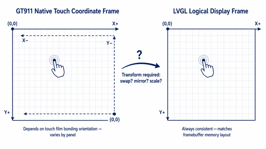
This is fundamentally a coordinate system disagreement. The GT911 reports raw touch coordinates in its own native reference frame, determined by how the touch film’s electrode matrix was bonded to the panel during manufacturing. LVGL expects coordinates in the display’s logical reference frame — origin at top-left, X increasing rightward, Y increasing downward, scaled to match the framebuffer resolution. When these two reference frames don’t agree — and they frequently don’t, for entirely ordinary manufacturing and integration reasons — the result is offset, mirrored, swapped, or scaled touch coordinates that look like a calibration failure but are actually a transform configuration problem.
This guide works through every layer of that disagreement: why offset happens, how axis rotation and mirroring are diagnosed and corrected, how resolution mismatches between the GT911’s configured active area and the actual panel cause systematic scaling errors, how portrait/landscape switching multiplies the complexity, and the calibration procedure that resolves persistent edge-of-screen inaccuracy that survives all of the above fixes.
Why Coordinate Offset Happens — The Manufacturing and Integration Root Causes
Touch coordinate offset is rarely a single cause — it’s usually one or more of four independent factors compounding: the touch film’s physical bonding orientation relative to the LCD’s pixel scan direction, a mismatch between the GT911’s configured active area and the panel’s actual resolution, an incorrect or missing axis transform in the driver layer, and physical calibration drift from the original factory settings. Each has a distinct signature, and distinguishing between them is the foundation of efficient debugging rather than trial-and-error flag-flipping.
Touch Film Bonding Orientation
During manufacturing, the capacitive touch film’s electrode matrix is laminated onto the LCD’s cover glass as a separate process step from the LCD’s own pixel addressing. The touch film has its own native coordinate origin determined by where the GT911 controller IC sits on the film’s flex circuit and which direction its internal X and Y electrode scan proceeds. There is no physical law requiring this to match the LCD’s pixel scan direction — it depends entirely on how the panel vendor’s tooling oriented the film during lamination, which can vary between vendors, between panel revisions from the same vendor, and occasionally between production batches if the film supplier changed.
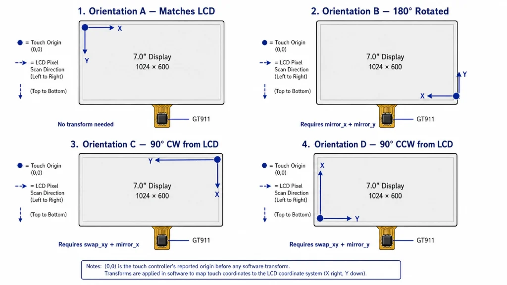
This is why two outwardly identical-looking 7-inch 800×480 panels from different suppliers — or even different batches — can require completely different swap_xy, mirror_xe mirror_y flag combinations despite running the exact same firmware. The flags aren’t compensating for a defect; they’re compensating for a legitimate manufacturing variable that the display interface specification doesn’t constrain.
Resolution and Active-Area Mismatch
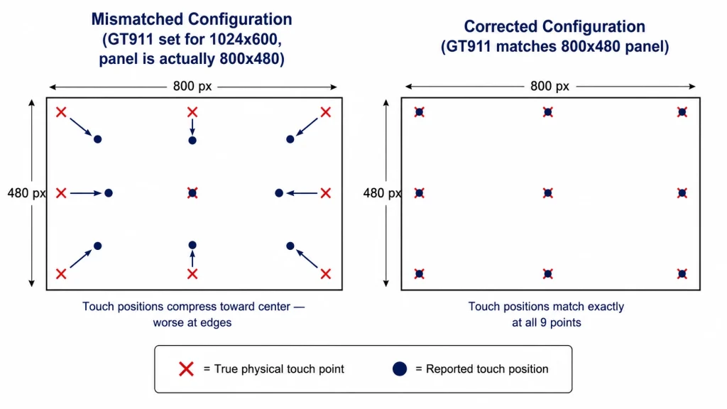
The GT911 stores its configured touch-sensing active area in internal registers 0x8068–0x806B, set during factory configuration to match the specific panel’s pixel dimensions. If this configuration doesn’t match the panel actually in use — common when a generic or default GT911 configuration ships with a display module rather than a panel-specific calibration — touch coordinates are reported in the wrong coordinate range entirely. A touch near the screen edge on an 800×480 panel whose GT911 thinks it’s configured for 1024×600 will report a coordinate value that, when passed unscaled to LVGL, lands roughly 28% short of the true edge — close enough to the correct area to look like rough calibration rather than an obvious configuration error.
Missing or Incorrect Driver-Layer Transform
Even when the GT911 itself is correctly configured for the panel’s resolution, the coordinate values it reports must still be transformed to match LVGL’s expected orientation if the touch film’s native origin doesn’t already align with LVGL’s top-left origin convention. This transform — typically implemented as a combination of axis swap, axis mirror, and origin inversion — must be applied in the driver layer between reading raw GT911 data and reporting it to LVGL’s input device callback. Skipping this step, or implementing only part of the needed transform, produces the swapped, mirrored, or rotated touch behavior that’s the most commonly reported GT911 + LVGL integration problem.
Calibration Drift from Mechanical or Environmental Stress
Less commonly, a panel that worked correctly at initial bring-up develops a progressive coordinate inaccuracy in the field — typically a uniform offset rather than a swap or mirror. This can result from mechanical stress on the touch film, from a corrupted or partially overwritten GT911 configuration block following an unexpected reset during firmware update, or rarely from genuine sensor aging. This category is distinguishable from the three above because it appears after a period of correct operation, rather than being present from the first power-on.
The Four-Corner Diagnostic — Identifying Which Transform You Need
Rather than guessing at flag combinations, a short, deterministic test identifies the exact transform required in under two minutes. This procedure isolates axis swap and mirroring from scaling and offset issues, which must be diagnosed and corrected separately.
Raw Coordinate Logging
Before applying any transform, instrument the touch read routine to print the raw GT911 coordinates — before any scaling, mirroring, or swapping logic — directly to the serial console. Then physically touch each of the four screen corners in sequence and record what raw value each produces.
Interpreting the Four-Corner Results
Compare the four raw readings against the expected pattern for a correctly oriented sensor, where touching TL should produce a low X and low Y value, TR should produce high X and low Y, and so on for an 800×480 panel where X ranges 0–800 and Y ranges 0–480. The pattern of deviation from this expectation directly identifies the required transform.
📌 Diagnose Swap/Mirror Before Touching Scale or Offset
Always resolve axis swap and mirroring first using raw, unscaled coordinates. Attempting to fix scaling or offset issues while the axes are still incorrectly swapped or mirrored produces confusing, seemingly inconsistent results, because the same scale correction behaves completely differently depending on which axis it’s actually being applied to. Fix orientation first; fix magnitude second.
Resolution Mapping — When Orientation Is Correct But Position Is Still Wrong
After confirming axis orientation is correct, a remaining systematic error — touches consistently landing a fixed percentage short of or beyond the true position, worse toward the screen edges — points to a resolution or scaling mismatch rather than an axis problem.
GT911 Active Area vs. Panel Resolution
Read the GT911’s configured active area directly from its configuration registers and compare against the panel’s actual pixel resolution.
The cleanest fix is correcting the GT911’s own configuration to match the panel exactly — request the correct configuration binary from the panel supplier rather than computing a runtime scaling correction, since a properly configured GT911 also reports more accurate raw sensitivity and noise filtering tuned for the actual electrode geometry. A runtime scale correction is a reasonable interim fix but treats a configuration error as a software problem rather than fixing it at the source.
esp_lcd_touch x_max / y_max Configuration
Independently of the GT911’s own configuration, the esp_lcd_touch_config_t struct used by the ESP-IDF touch driver layer has its own x_max e y_max fields that determine how raw GT911 coordinates are normalized before being passed to LVGL. These must also match the panel’s actual resolution — a common mistake is leaving these at a default value copied from an example project for a different panel size.
Portrait/Landscape Switching — Where Static Configuration Breaks
Static swap_xy, mirror_xe mirror_y configuration, set once at firmware initialization, handles a fixed display orientation correctly. It breaks the moment an application needs to switch between portrait and landscape at runtime because the correct touch transform for landscape mode is not simply the same transform applied to swapped dimensions; it requires its own independent flag combination.
LVGL’s own display rotation feature, such as lv_display_set_rotation() in LVGL 9.x, rotates the rendered framebuffer content, but it does not automatically rotate touch input coordinates to match. This must be handled explicitly in the touch read callback, recalculating the appropriate transform based on the currently active display rotation state.
The implementation pattern that scales cleanly to runtime rotation switching is to apply the touch transform as an explicit function of the current rotation state, re-evaluated inside the touch read callback on every call, rather than as a one-time flag set at initialization.
⚠ Test Each Rotation State Independently
A transform formula that’s correct for one rotation state derived analytically can still be wrong for another if the touch film’s bonding orientation introduces an asymmetry the formula didn’t anticipate. Run the four-corner diagnostic separately at each supported rotation state during bring-up — it takes a few extra minutes per orientation and eliminates an entire category of field complaints that only appear when the product is mounted in its less-common orientation.
Touch-Area Calibration — Resolving Edge Inaccuracy That Survives the Above Fixes
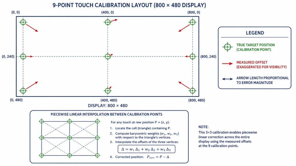
After axis orientation and resolution scaling are both corrected, a small residual inaccuracy can remain — typically most noticeable within 10–15 pixels of the screen edges or corners — caused by minor nonlinearity in the touch film’s electrode response near its physical boundary, or by a small mechanical offset between the touch film’s true active area and the GT911’s configured boundary. This is what classic 9-point or 5-point touch calibration addresses, and it’s a distinct correction layer from the swap/mirror/scale fixes already covered.
The 9-Point Calibration Procedure
Display nine calibration targets in sequence — the four corners, the four edge midpoints, and the center — each inset 5–8% from the true edge to keep the target comfortably within the touch film’s most linear response region. Record the raw touch coordinate reported for each target tap, then compute a piecewise linear or low-order polynomial correction that maps each measured point to its known true position.
For most GT911 industrial panels with correctly matched active-area configuration, the correction derived from this 9-point map is small — typically under 1% of screen dimension — and a simpler 5-point calibration is sufficient. Reserve the full 9-point procedure for panels showing visibly non-uniform edge response, or for product lines where touch accuracy is safety-relevant and the additional verification is justified.
Summary — The Correction Order That Avoids Wasted Debugging Time
GT911 touch coordinate problems resolve fastest when corrected in a specific sequence, because each layer’s correction assumes the layers before it are already fixed. Attempting calibration before fixing axis swap, or attempting resolution scaling before confirming orientation, produces confusing intermediate results that don’t actually indicate a deeper problem — just that the layers are being addressed out of order.
This diagnostic sequence — orientation, then scaling, then rotation handling, then fine calibration — builds directly on the broader GT911 + LVGL integration practices covered in Kadi Display’s guide on connecting a GT911 capacitive touch panel to LVGL on ESP32-S3, which recommends printing raw GT911 coordinates at the four panel corners as the starting diagnostic before applying any coordinate mapping. For teams sourcing display modules where this category of integration work is minimized through factory-matched GT911 configuration, Kadi Display’s industrial TFT LCD display module range includes panels with confirmed active-area configuration and documented touch film orientation, reducing resolution-mismatch and orientation-guessing before the unit reaches the bring-up bench.
Referência de produto e suporte técnico
For GT911-equipped industrial TFT-LCD touch display modules with factory-matched active-area configuration and documented touch film orientation, contact Kadi Display at Sales@sz-kadi.comServiços OEM e ODM disponíveis. Browse industrial touch display modules →
Isenção de responsabilidade: Code examples, register addresses, and calibration values in this guide are illustrative references and must be verified against your specific GT911 module, ESP-IDF/LVGL version, and panel datasheet. Touch film bonding orientation varies by supplier and panel revision; always perform the four-corner diagnostic on your specific hardware rather than assuming flag values from a different project. GT911 is a trademark of Shenzhen Goodix Technology Co., Ltd. LVGL is open-source software under MIT license. ESP32-S3 is a trademark of Espressif Systems. All other trademarks belong to their respective owners.
PRIVENTE
ESP32-S3 RGB Display with GT911 and LVGL: A Practical Guide for Kiosk and HMI Applications
NEXTO
LCD Pressure Damage: Why Industrial Touchscreens Develop Spots After Installation
Deixe um comentário

Recent Blog & News
- Industrial LCD EOL: What Happens from Pre-Announcement to Replacement Mass Production?
- Electronic Component Obsolescence Management for Industrial Displays: An OEM Guide
- How to Develop a Production Ready Custom Display Assembly TFT Module Touch Cover Glass FPC Bonding and Mounting
- 15 Pin vs 22 Pin Raspberry Pi DSI Connectors Cable Pinout and Compatibility
- Native MIPI DSI vs LVDS or HDMI Bridge: An OEM Display Architecture Decision Guide

