




Casa
-
Blog & Novas
-
MIPI DSI Display Not Turning On: Interface, Driver and Initialization Checks for Embedded HMI
MIPI DSI Display Not Turning On: Interface, Driver and Initialization Checks for Embedded HMI
2026-07-16
16:25
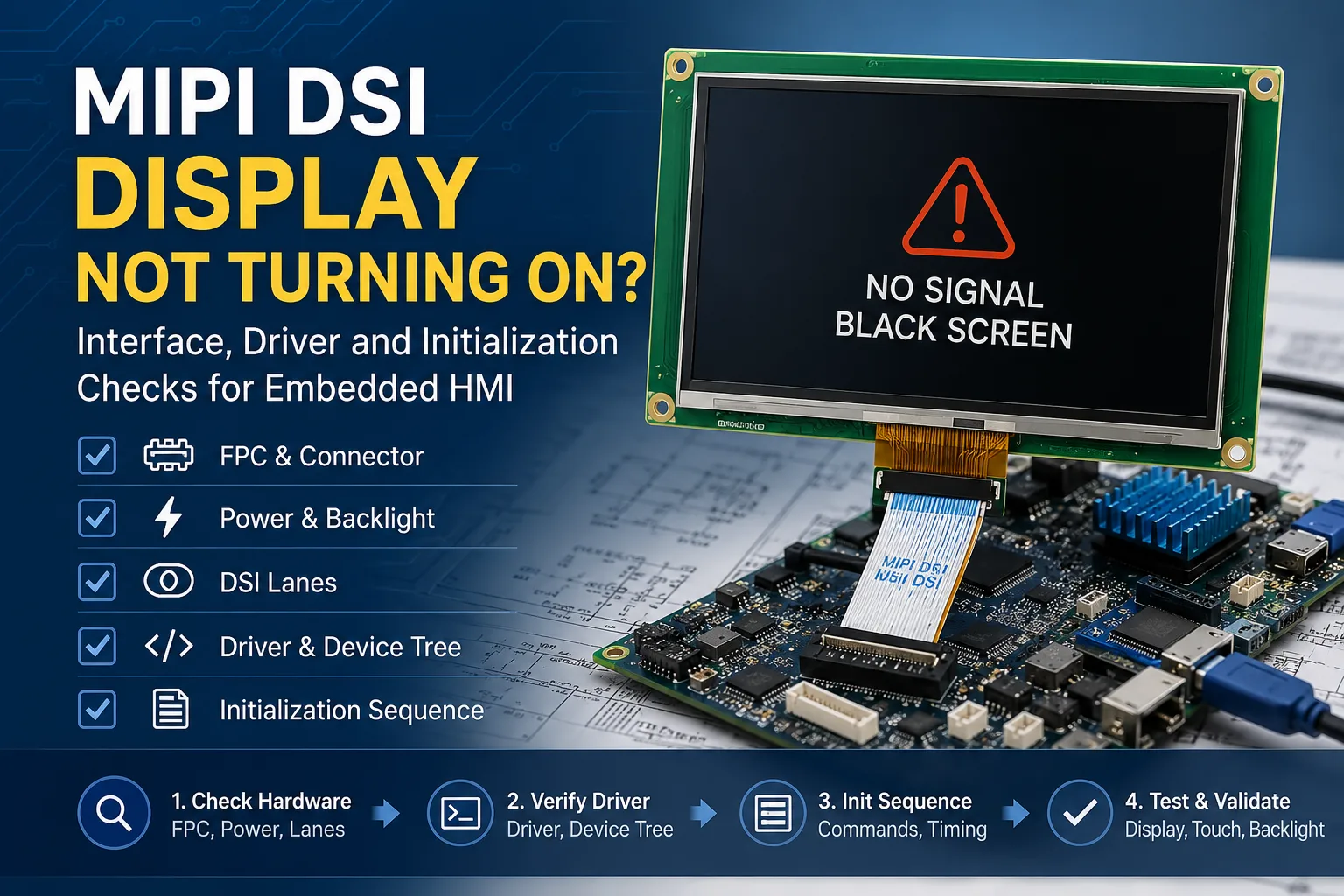
A MIPI DSI display not turning on in an embedded HMI project does not always mean the panel is defective. In industrial control terminals, embedded Linux systems, Android devices, medical equipment, and automation terminals, a black screen may come from FPC direction, power sequencing, reset control, DSI lane configuration, panel timing, initialization commands, Device Tree settings, or an unavailable panel driver. Before replacing the display module, engineers and B2B buyers should check the full signal path from the host board to the display, touch interface, and backlight system.
What “MIPI DSI Display Not Turning On” Usually Means
No power, no backlight, or backlight on but no image
The first step is to identify the failure type. If there is no power and no backlight, check the connector, logic voltage, backlight voltage, enable pin, and power sequence. If the backlight turns on but there is no image, the display may be receiving power while the MIPI DSI image path is not starting correctly. In that case, the likely causes are DSI lane mismatch, missing initialization sequence, wrong panel driver, Device Tree error, or incorrect timing.
If the image appears briefly and then disappears, reset sequence, sleep-out commands, display-on commands, timing, firmware behavior, or power stability should be reviewed.
Blank screen after boot vs display not detected
A blank screen after boot is different from a display that is not detected at all. If the system log shows that the DSI host and panel driver are loaded, the problem may be timing, initialization, lane configuration, or backlight control. If the panel node is not enabled or the driver does not bind, the issue may be Device Tree, overlay, compatible string, kernel configuration, or missing driver support.
Why MIPI DSI failures often look like panel defects
MIPI DSI failures often appear as a simple black screen, but the root cause may be outside the LCD panel. A reversed FPC, wrong lane number, missing reset GPIO, incomplete initialization command table, wrong video mode, or unsupported display driver IC can all prevent the panel from displaying an image.
If the project is still in the interface selection stage, LVDS vs MIPI for industrial TFT LCD displays explains why MIPI DSI is often used for compact embedded systems with short internal connections, while LVDS is often reviewed for larger industrial displays or stronger EMC environments.
Hardware Checks Before Changing Drivers
Check FPC cable direction, connector contact and lane routing
Before editing a driver, check the physical connection. MIPI DSI FPC cables are direction-sensitive, and the connector pinout must match the host board. A cable that looks inserted may still have poor contact if the latch is not fully locked or the FPC is slightly offset.
Engineers should confirm the FPC exit direction, connector pitch, lane wiring, clock lane, and whether the cable is bent, compressed, or routed through a mechanically stressed area inside the enclosure.
Verify display logic power, backlight power and reset sequence
A MIPI DSI touch display may require separate logic power, backlight power, reset control, and enable signals. The display may remain black if power rails start in the wrong order, reset is not released correctly, or the backlight control is not configured.
Backlight behavior should also be separated from image data. If the backlight can be controlled independently but no image appears, the DSI signal, panel driver, Device Tree, or initialization sequence should be checked next.
Confirm the DSI lane number and clock lane connection
MIPI DSI panels may use different lane configurations, such as one, two, or four data lanes, plus a clock lane. The host board, cable, and panel must all support the same lane number and lane mapping. If the host output is set for the wrong lane count or the panel requires a different configuration, the screen may stay black, flicker, or show distorted images.
Test whether the backlight can be controlled independently
Independent backlight control helps identify the failure layer. If the backlight does not turn on, check power, enable, PWM, and backlight driver behavior. If the backlight works but the image does not, focus on DSI signal, panel initialization, driver binding, and timing parameters.
Software and Driver Checks for MIPI DSI Bring-Up
Confirm whether the panel driver exists or must be adapted
A connector-compatible display is not automatically software-compatible. The kernel may need a panel driver for the specific display driver IC, timing, initialization command set, and power sequence. If a driver exists for a similar panel, it may still require adaptation for resolution, porch values, reset timing, color format, or command mode.
For B2B embedded HMI projects, the driver IC and initialization sequence should be confirmed before sample approval.
Check Device Tree, overlay and display node status
For Linux and Yocto systems, Device Tree configuration is often central to MIPI DSI display bring-up. Check whether the DSI host is enabled, the panel node is active, the compatible string matches the driver, the reset GPIO is defined, and the backlight node is connected correctly.
Lane number, panel timing, regulator references, and display mode should be checked against the product specification. A small configuration mismatch can cause a MIPI DSI display black screen even when the hardware connection is correct.
Review initialization commands from the display supplier
Many MIPI DSI displays require an initialization command sequence before the panel can show an image. This may include reset timing, sleep-out, display-on, gamma settings, color format, video mode or command mode, and other driver IC commands.
If the initialization table is missing, incomplete, or does not match the actual panel revision, the display may remain blank after initialization. Buyers should ask the display supplier for the required initialization data when the host platform needs custom driver integration.
Match panel timing, pixel clock and video/command mode
The panel timing must match the display specification. Confirm resolution, refresh rate, pixel clock, horizontal and vertical porch values, color format, and whether the panel uses video mode or command mode. These parameters should be reviewed together with host bandwidth and lane configuration.
Common Symptoms and Likely Causes
Symptom-to-cause matrix
|
Sintoma |
Likely Causes |
First Checks |
|
No power, no backlight |
Power input, connector, enable pin |
Logic power, backlight power, FPC seating |
|
Backlight on but no image |
DSI lane, panel driver, Device Tree, init sequence |
Logs, panel node, lane number, init commands |
|
Screen stays black after initialization |
Wrong init commands, mode setting, timing |
Init table, driver IC, video/command mode |
|
Image appears briefly and disappears |
Reset, power sequence, timing, firmware |
Reset GPIO, prepare/enable sequence |
|
Flickering or distorted image |
Pixel clock, lane bandwidth, color format |
Timing, lane count, porch values |
|
Touch works but display does not |
Touch interface separate from DSI image path |
I2C/SPI/USB touch vs MIPI DSI display |
|
Display works but touch does not |
Touch controller, driver, cable pins |
Touch IC, OS driver, touch interface |
Backlight on but no image
This is one of the most common MIPI DSI troubleshooting scenarios. It usually means power and backlight may be available, but image data is not reaching the panel correctly. Check whether the DSI host is active, the panel driver is bound, the initialization sequence is sent, and the lane number and timing match the panel.
Touch works but display does not, or display works but touch does not
Touch and display should be diagnosed separately. MIPI DSI normally carries display image data, while touch may use I2C, SPI, or USB depending on the module. A working touch controller does not prove that the MIPI DSI image path is correct, and a working display does not prove that the touch driver is configured.
How to Prevent MIPI DSI Bring-Up Problems Before Sampling
Confirm driver IC, initialization sequence and timing data
Before requesting a sample, buyers should confirm the display driver IC, resolution, timing table, initialization command sequence, reset behavior, backlight control, color format, and video or command mode. These details are more important for MIPI DSI than for many plug-and-play monitor interfaces.
Match lane number, FPC pinout and connector direction
The host board must support the same lane number and connector assignment as the display module. FPC direction, pinout, cable length, and enclosure routing should be reviewed during the design stage. If the FPC must exit in a special direction, this should be discussed before sample production.
Ask for Linux, Android or RTOS support information if needed
Embedded HMI projects may use Linux, Android, RTOS, or a custom BSP. Buyers should ask whether timing data, initialization commands, driver reference information, or porting support can be provided. The level of software support may vary by platform, driver IC, operating system, and project configuration.
Validate display, touch and backlight together
Sample validation should include image output, touch response, brightness control, reset and wake behavior, long-running display, and final enclosure cable routing. A display that turns on during bench testing may still fail if the final device changes the cable path, power sequence, or software configuration.
When Should You Request a Custom MIPI DSI Display Module?
When standard MIPI DSI panels do not match the host board
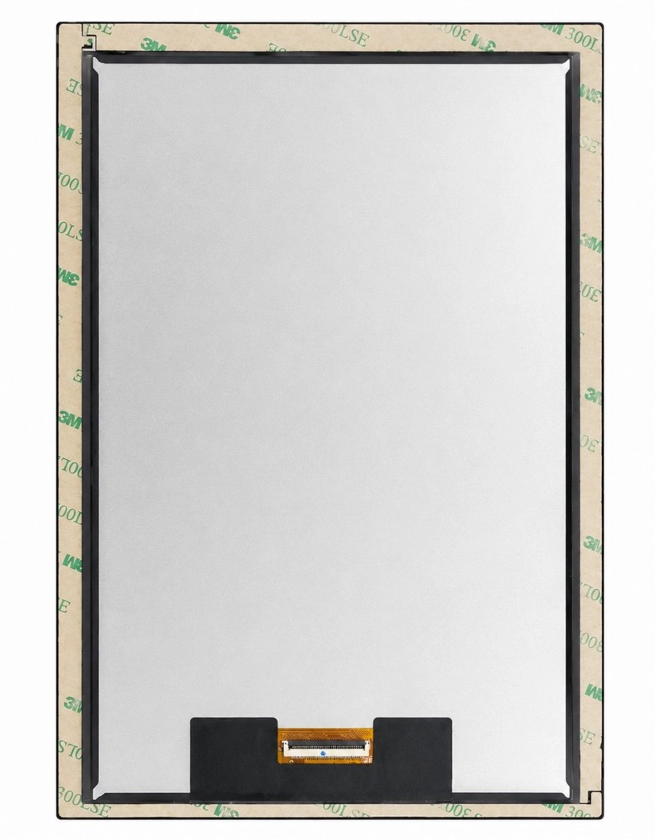
A custom MIPI DSI display module may be needed when the standard panel does not match the host lane number, connector pinout, FPC direction, timing, driver IC, backlight requirement, or mechanical structure. A 10.1 inch MIPI DSI touch display for embedded HMI can be used as a reference option for projects requiring an 800×1280 MIPI DSI display, capacitive multi-touch, and embedded application compatibility checks.
When FPC, backlight, touch or cover glass needs customization
For industrial HMI, medical equipment, Android devices, embedded Linux systems, and automation terminals, customization may involve FPC direction, cable length, capacitive touch, OCA bonding, cover glass, brightness, backlight, or mechanical outline. The actual requirements should be verified against the product specification and device structure.
What to send to a display supplier before sample approval
A useful RFQ should include the host platform or SoC, operating system, display size, resolution, DSI lane number, FPC pinout, connector drawing, target brightness, touch interface, mechanical drawing, application environment, boot log or failure video, target quantity, and lifecycle requirement.
For projects that require display module matching, touch integration, FPC review, or embedded display customization, an industrial TFT LCD and custom display manufacturer can help review whether the display, cable, touch panel, and software data are suitable for the target device. Kadi Display’s Shenzhen display manufacturer for industrial and medical display solutions page can also be used to review company background before technical communication.
Conclusão
A MIPI DSI display not turning on should be diagnosed as a system-level issue. The cause may be hardware connection, power sequence, reset control, DSI lane configuration, panel timing, missing initialization commands, Linux Device Tree errors, driver mismatch, or touch/backlight separation. The most practical approach is to confirm physical connection first, then verify software configuration, initialization data, timing, and sample conditions.
For project review, Shenzhen Kadi Display Technology., Ltd. can evaluate host platform, display size, resolution, DSI lane number, FPC direction, initialization data, operating system, touch interface, application environment, drawings, sample requirements, target quantity, and lifecycle expectations before recommending a standard or customized display module.
FAQ
Q1: Why does my MIPI DSI display have backlight but no image?
A1: Backlight on but no image usually means the power and backlight path may be working, but the MIPI DSI image path has not started correctly. Check DSI lane number, panel driver, Device Tree, initialization sequence, timing, reset control, and logs.
Q2: Does every MIPI DSI display need an initialization sequence?
A2: Many MIPI DSI displays need an initialization command sequence, especially when the panel uses a specific display driver IC. The exact commands and timing should be verified against the panel specification and host platform requirements.
Q3: Can a wrong DSI lane number stop the display from turning on?
A3: Yes. A wrong DSI lane number, lane order, or clock lane setting can stop the display from showing an image. It may also cause a black screen, flickering, distorted image, or unstable behavior.
Q4: Is MIPI DSI touch controlled through the same interface?
A4: Usually no. MIPI DSI is mainly used for display image data. Touch is often handled through I2C, SPI, or USB, so display failure and touch failure should be checked separately.
Q5: What should I ask a supplier before buying a MIPI DSI display module?
A5: Ask for the display driver IC, lane number, FPC pinout, connector drawing, initialization sequence, timing data, touch interface, backlight control, operating system support information, mechanical drawing, and lifecycle requirement.
PRIVENTE
Why Does an LVDS Display Flicker in Industrial Equipment? Causes and Design Checks
NEXTO
How to Choose Display Interfaces for Rugged Industrial HMI and Panel PC Projects
Deixe um comentário

Recent Blog & News
- Industrial LCD EOL: What Happens from Pre-Announcement to Replacement Mass Production?
- Electronic Component Obsolescence Management for Industrial Displays: An OEM Guide
- How to Develop a Production Ready Custom Display Assembly TFT Module Touch Cover Glass FPC Bonding and Mounting
- 15 Pin vs 22 Pin Raspberry Pi DSI Connectors Cable Pinout and Compatibility
- Native MIPI DSI vs LVDS or HDMI Bridge: An OEM Display Architecture Decision Guide

