




Casa
-
Blog & Novas
-
MIPI DSI Connector and FPC Pinout Check: How to Compare a Display Module with Your Host Board
MIPI DSI Connector and FPC Pinout Check: How to Compare a Display Module with Your Host Board
2026-08-14
00:00
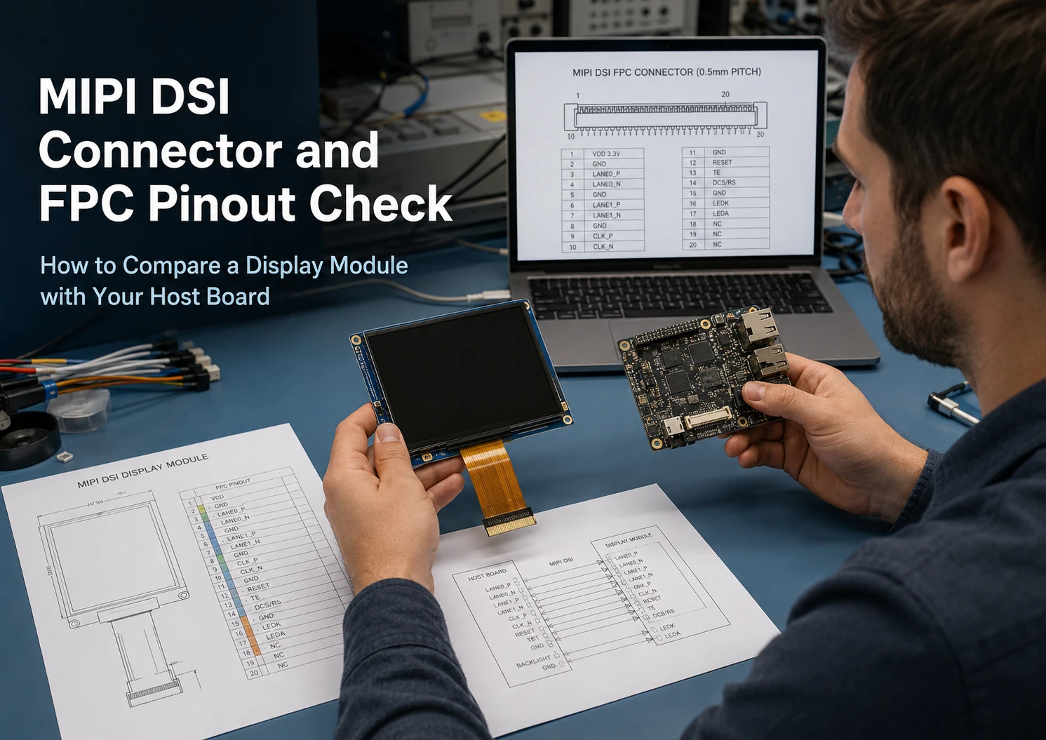
A matching connector or pin count does not confirm that a MIPI DSI display will work with a host board. A reliable MIPI DSI connector pinout check must also cover contact pitch, FPC orientation, lane mapping, voltage rails, control signals, touch wiring, panel initialization, software support, and mechanical routing. Before connecting or ordering a module, compare the exact host-board schematic with the display specification and FPC drawing. The result may support a direct connection, require an adapter or modified assembly, or show that another display architecture is more appropriate.
Start with the Exact Host Board and Display Documents
Begin with exact part numbers rather than general descriptions such as “MIPI-compatible board” or “7-inch DSI display.”
Record the following information:
-
Host processor or SoC part number
-
Mainboard or carrier-board model and revision
-
DSI connector reference designator
-
Display module part number and revision
-
Display driver IC, when identified
-
Touch-controller part number, when applicable
-
Intended operating system, BSP, or kernel version
A processor may include a MIPI DSI host controller while the finished board does not route that interface to an accessible connector. Also confirm that the port is DSI rather than CSI. Both may use a related physical layer, but DSI connects a host processor to a display, while CSI is intended for cameras. MIPI Alliance defines DSI as a high-speed serial interface between a host processor and a display module.
Collect the host-board schematic or connector pinout, the connector manufacturer’s drawing, the display specification, the display FPC drawing, and the mechanical drawing. For a touch module, include the touch-panel specification as well.
Também exibe complete MIPI DSI compatibility checklist covers the broader host, lane, timing, initialization, and operating-system review. This cluster article focuses on the connector and FPC comparison that should be completed before those specifications are treated as a working system match.
Do the Connector and FPC Physically Match?
The physical review starts with pin count, but it does not end there.
Compare Pin Count, Pitch, and Connector Construction
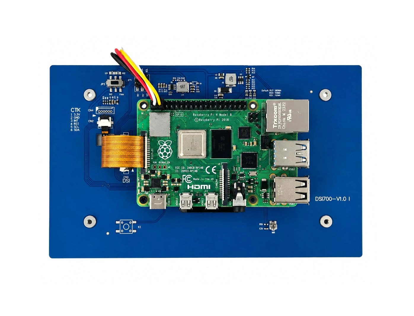
Check the number of contacts and the contact pitch on both sides. Two connectors may each have 15 pins but use different pitches, widths, FPC thickness ranges, exposed-conductor lengths, or latch designs.
Where possible, compare the actual connector manufacturer and part number. The mating drawing can confirm:
-
Contact pitch
-
FPC thickness range
-
Required conductor exposure
-
Stiffener requirements
-
Mated height
-
Insertion depth
-
Latch or locking mechanism
A cable that fits loosely, does not reach the contact area, or cannot be secured by the latch is not a valid connection even when the pin count appears correct.
Check Contact Side and Pin 1 Orientation
Determine whether each connector is top-contact, bottom-contact, or dual-contact. Then confirm whether the FPC requires conductors on the same side or opposite sides at its two ends.
Pin 1 must be identified from the drawing’s stated viewing direction. Do not infer Pin 1 from a product photograph or from the direction in which text is printed on the cable.
Raspberry Pi provides a useful platform-specific example. Raspberry Pi 4 and earlier boards use a standard 15-pin, 1.0 mm-pitch DSI connector, while Raspberry Pi 5 uses mini 22-pin, 0.5 mm-pitch combined camera/display connectors. The official Touch Display documentation specifies a 22-to-15-way FFC for Raspberry Pi 5 and gives different contact-orientation instructions for the display and board ends.
That defined cable works within the specified Raspberry Pi system. It should not be treated as evidence that any 22-pin host can connect to any 15-pin MIPI DSI display.
Confirm FPC Routing Inside the Device
The FPC must also fit the mechanical design. Review:
-
Cable length and exit direction
-
Minimum practical bend area
-
Stiffener position
-
Connector access during assembly
-
Clearance around the latch
-
Display and mainboard orientation
-
Risk of cable pinching or twisting
-
Enclosure and mounting-bracket interference
A correct electrical pinout can still produce an unsuitable assembly if the FPC must fold sharply, crosses a fastening point, blocks another connector, or cannot be installed after the enclosure is closed.
Does Every Pin Carry the Correct Signal?
After confirming the physical interface, create a pin-by-pin mapping between the host and display.
Microchip documentation provides a clear reason for this step: one of its development boards uses a 22-pin MIPI connector, requires a 22-to-15-pin adapter for certain Raspberry Pi displays, and notes that four-lane displays from different manufacturers may need adapters because connector pinouts vary.
Use a comparison table such as the following:
| Host Pin | Host Signal | Display Pin | Display Signal | Voltage or Direction | Review Result |
|---|---|---|---|---|---|
| 1 | From host schematic | 1 | From display drawing | Confirm level/direction | Match, remap, or unresolved |
| 2 | From host schematic | 2 | From display drawing | Confirm level/direction | Match, remap, or unresolved |
| … | Continue for every pin | … | Continue for every pin | Include power and GPIO | Document action |
The signal review should identify:
-
Clock lane P and N
-
Data lane 0 P and N
-
Data lane 1 P and N
-
Data lanes 2 and 3 when used
-
Differential-pair polarity
-
Ground and shield positions
-
Panel logic power
-
I/O power
-
Reset and enable signals
-
Backlight power, enable, and PWM
-
Touch SDA, SCL, reset, and interrupt
-
TE or synchronization signals
-
Reserved and no-connect pins
Do not assume that the same pin number carries the same signal on two modules. A pin used for ground on one design may be assigned to power or control on another. Likewise, a passive cable cannot correct a power-rail conflict.
Are Power, Reset, Backlight, and Touch Connections Compatible?
MIPI DSI carries the display data link, but a usable touch display module may require several additional electrical paths.
Compare the Power Architecture
Check the exact product specification for:
-
Panel logic voltage
-
I/O voltage
-
Backlight input
-
Required current capacity
-
Ground arrangement
-
Power-on and power-off sequence
-
Delays between power, reset, initialization, and backlight enable
Do not apply a common voltage from another display simply because its connector and resolution are similar. A mismatch can prevent startup and may expose the host or module to electrical risk.
Backlight power should be reviewed separately from panel logic power. A lit backlight only confirms that part of the power path is active; it does not confirm that the DSI image path, reset sequence, timing, or driver is correct.
Review Reset, Enable, PWM, and Touch
Identify the required polarity and timing for panel reset, display enable, backlight enable, and PWM. For a capacitive touch panel, check the touch-controller voltage, communication interface, reset, and interrupt lines.
Touch may use I²C, USB, or SPI rather than the DSI video link. A display image can work while touch remains unavailable, and touch communication can work while the panel remains black.
Some platform-oriented products combine video, touch control, and power in a defined FPC arrangement. Kadi’s MIPI DSI displays for Raspberry Pi include products designed around specified Raspberry Pi connections, but the arrangement must still be checked against the selected product and board model.
Does the Connected Pinout Support the Required DSI Link?
A correct pin map is necessary, but it is not a complete interface match.
Confirm that the selected host port supports the display’s required number of data lanes. The host, board routing, cable, and panel must agree on the active lane count and lane assignment. A four-lane panel cannot use four lanes if the board connector routes only two.
Also review:
-
Complete horizontal and vertical timing
-
Required pixel clock
-
Lane-rate range
-
Pixel format, such as RGB565, RGB666, or RGB888
-
Video mode or command mode
-
Burst or non-burst operation
-
Panel-specific initialization requirements
Resolution alone is insufficient. Two 1024 × 600 displays can use different porch values, synchronization widths, pixel clocks, and lane rates. Kadi’s existing bandwidth article explains why the calculation should use complete panel timing rather than active resolution alone.
O 7-inch 1024×600 MIPI DSI touchscreen for Raspberry Pi is an example of a product page that identifies a specific platform-oriented DSI interface and I²C touch arrangement. Those published details support evaluation for the stated Raspberry Pi use case; another processor or custom host board would require its own pinout, timing, power, and software review.
Will the Host Software Initialize the Display?
Physical and electrical compatibility do not confirm software compatibility.
For an embedded Linux project, determine whether the software environment includes or can support:
-
The SoC’s DSI host-controller driver
-
A panel driver for the display driver IC
-
Display timing definitions
-
Data-lane and pixel-format configuration
-
Regulator definitions
-
Reset and enable GPIOs
-
Backlight control
-
Panel-specific initialization commands
-
A Device Tree node or platform-specific overlay
Linux’s MIPI DSI Device Tree binding describes the DSI bus and associated peripherals, while panel bindings may include power supplies, backlight references, enable GPIOs, and other panel properties. More advanced panels can require dedicated bindings and driver support.
A Device Tree entry is a hardware description, not proof that the selected panel will initialize. The compatible string, lane count, timing, reset sequence, regulators, and driver implementation still need to match the hardware.
Treat touch as a separate software path. Confirm that the operating system supports the touch controller and that its bus, address, interrupt, reset line, and orientation settings can be configured.
Direct Cable, Passive Adapter, Modified Module, or Custom Assembly?
Once the comparison is complete, classify the integration path.
A direct FPC connection may be suitable when the connector, contact orientation, pin mapping, voltage rails, lane configuration, software path, and mechanical routing already match.
A passive adapter cable or adapter PCB may be appropriate when the core electrical interface is compatible and the difference is limited to connector format or pin order. A passive adapter does not provide voltage conversion, protocol conversion, missing lane support, new panel initialization, or a software driver.
A modified display module may be more suitable when the DSI link is usable but the project needs a different FPC length, cable exit direction, connector, pinout arrangement, touch configuration, or mounting format.
A custom display assembly can extend the module-level design to include elements such as a cover lens, bonding, brackets, PCBA, connector placement, or enclosure integration, depending on the documented project requirements and available product options.
Where the host cannot directly support the panel, a controller-based or modular HMI architecture may be more practical than forcing a native DSI connection. The decision depends on the host output, operating system, mechanical space, power design, and required integration level. Kadi Display presents these broader routes through its industrial display and integration solutions.
Use a Go, Adapter, Modify, or Stop Decision Checklist
Proceed to sample evaluation when:
-
The connector and FPC drawings align
-
Every pin has been mapped
-
Voltage rails and control signals match
-
Required DSI lanes are routed
-
Timing and lane rate are supportable
-
A panel-driver or adaptation path is identified
-
The FPC fits the preliminary mechanical design
Consider an adapter when the electrical and software requirements match but the connector form factor or pin order differs.
Consider a modified module or custom assembly when the core DSI interface is suitable but the FPC, touch layer, cover lens, bonding, bracket, or cable routing does not fit the device.
Pause the connection or purchase when:
-
Pin 1 or the drawing orientation is unclear
-
A complete pinout is unavailable
-
Power voltage or sequencing is unknown
-
Required lanes are missing
-
Timing or lane-rate support cannot be confirmed
-
Panel initialization information is unavailable
-
The decision is based only on screen size, resolution, connector appearance, or pin count
Complete-system validation should follow the document review. Evaluate cold boot, restart behavior, image stability, touch response, backlight control, suspend and resume, FPC routing, enclosure clearance, and system power margin under the project’s intended conditions.
Conclusão
A MIPI DSI connector match is only the beginning of a compatibility decision. Compare the physical connector, FPC orientation, complete pin mapping, power architecture, control signals, touch path, DSI link requirements, driver support, and mechanical installation before ordering or applying power.
For an initial project discussion, discuss your MIPI DSI display requirement with Kadi Display and provide the host processor, board model and revision, connector pinout, target size and resolution, touch requirement, operating system, display or mechanical drawing, FPC direction, and application. Compatibility should then be reviewed against the exact product specification and host documentation.
FAQ
Are all MIPI DSI connector pinouts the same?
No. MIPI DSI defines the interface between a host processor and a display module, but finished modules and development boards may use different connector sizes, pitches, pin assignments, voltage rails, and control signals. Compare the exact host and display drawings.
Can a 15-pin MIPI DSI display connect to a 22-pin host?
It may be possible when a defined cable or adapter maps the correct signals and both devices match in voltage, lane count, timing, operating mode, and software support. The Raspberry Pi 22-to-15-way FFC is a platform-specific example rather than a universal conversion method.
Can a passive adapter correct any MIPI DSI pinout difference?
A passive adapter can change connector format or remap compatible signals. It cannot create missing lanes, convert incompatible voltages or protocols, change panel timing requirements, or provide a missing driver and initialization sequence.
Why can a connector-compatible display still show a black screen?
Possible causes include incorrect lane configuration, unsuitable timing, missing initialization commands, reset or power-sequence errors, Device Tree configuration, driver mismatch, or backlight control. Hardware seating and pinout should be checked before software changes, but both layers require verification.
PRIVENTE
Can Your Host and Panel Support MIPI DSI Command Mode? An Embedded HMI Selection Checklist
NEXTO
Can You Reuse a MIPI DSI Display Across SBCs and SoMs? A Host Migration Checklist
Deixe um comentário

Recent Blog & News
- MIPI DSI Display Driver Development for Embedded Linux What Hardware Buyers Need to Confirm
- How to Diagnose an LCD That Is Slow Flickers or Fails to Start in the Cold
- Why PCAP Touchscreens Need Retuning After Cover Glass Coating or Optical Bonding Changes
- Why Outdoor LCDs Fog Inside: Condensation, Sealing, Vents, and Heaters
- IP65 vs IP67 Industrial Displays: What the Rating Actually Covers

