




Casa
-
Blog & Novas
-
MIPI DSI Works After Power-On but Goes Black After Warm Reboot: Reset and Reinitialization Checks
MIPI DSI Works After Power-On but Goes Black After Warm Reboot: Reset and Reinitialization Checks
2026-09-04
00:00
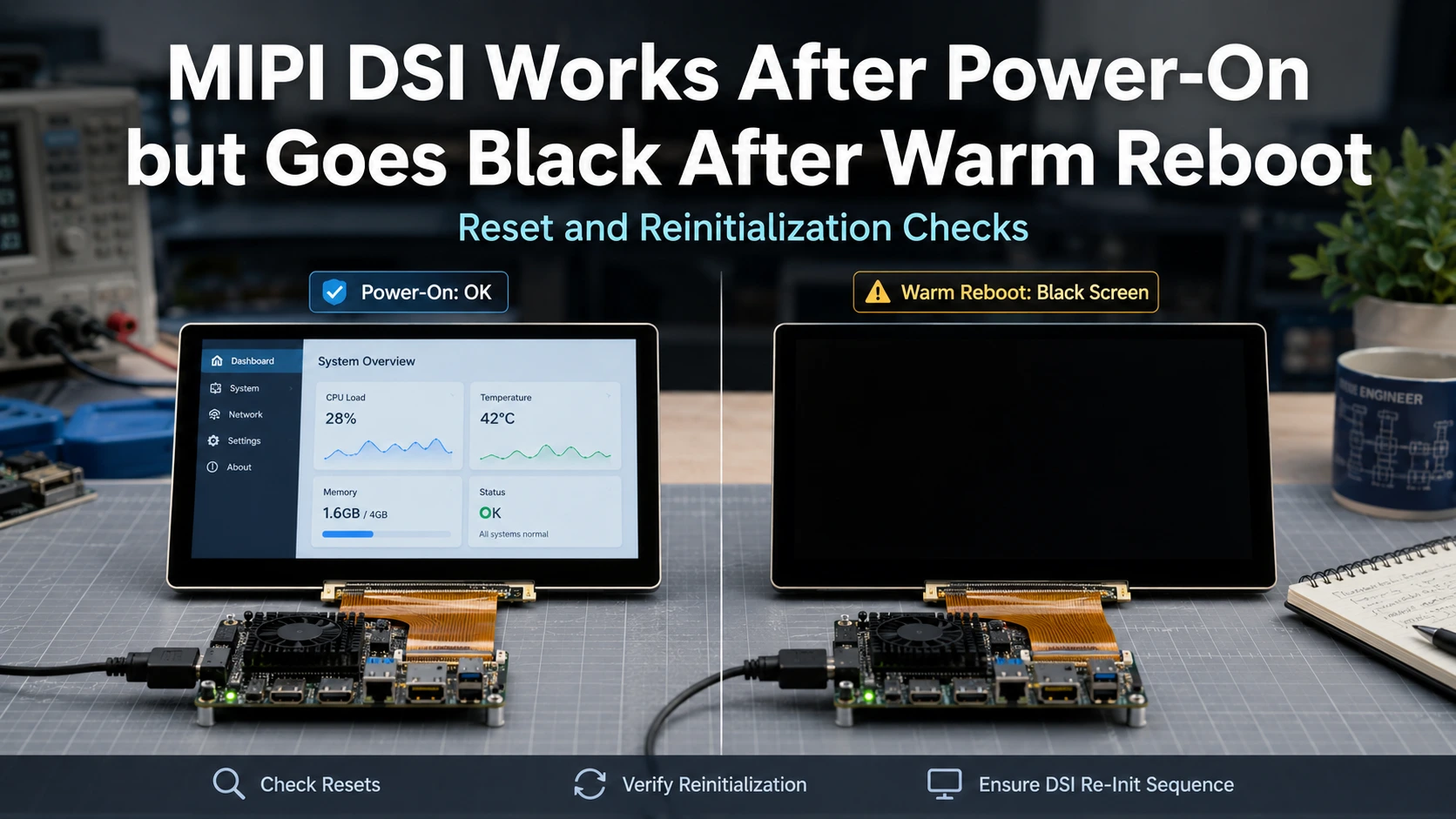
If a MIPI DSI display works after a full power-on but goes black after a warm reboot, treat the difference between the two startup paths as your main diagnostic clue. A power cycle may clear panel, bridge, regulator, and reset states that a software reboot does not reproduce in the same way.
Start by comparing reset behavior, panel power-down, Linux DRM panel lifecycle, and reinitialization. Do not change lane count, display timing, FPC, or the panel itself until the evidence points to those layers.
Quick Check: Is Warm Reboot Really Different from a Full Power Cycle?
Before changing configuration, make the failure repeatable.
Run two controlled tests with the same host, carrier board, display module, FPC, driver, and software configuration.
For the first test, remove system power, return the equipment to its normal powered-off state, and then power it on. Confirm whether the image, backlight, and touch function normally.
For the second test, perform a warm or software reboot without removing system power. Record whether the image returns, whether the backlight comes on, whether touch still responds, and whether the kernel reports panel or DSI errors.
This A/B comparison matters because Kadi’s existing MIPI DSI display bring-up checklist already treats cold starts, warm restarts, and recovery behavior as separate validation conditions rather than assuming one successful boot proves system stability.
If cold boot itself is inconsistent, return to a complete bring-up investigation covering power, reset, DSI configuration, initialization, and timing. If cold boot works repeatedly but warm reboot fails repeatedly, focus on what state the reboot path failed to clear or restore.
Build the Warm-Reboot Fault Tree Before Changing Timing or Lanes
A black screen after reboot does not identify one universal cause. The symptom should determine the first layer you inspect.
| Symptom After Warm Reboot | First Check | Suspected Layer |
|---|---|---|
| No backlight and no image | Power, enable, reset | Power/control path |
| Backlight on but image black | Panel reset and initialization | Panel lifecycle |
| Driver binds but no image appears | Prepare/enable and DSI initialization | DRM/panel driver |
| Manual panel reset restores image | Reset behavior | GPIO/driver lifecycle |
| Full power cycle restores image | Power-down state | Rail/reset/retained state |
| Image works but touch fails | Touch reset and interface | Separate touch path |
Backlight, panel electronics, MIPI DSI transmission, and touch should be treated as separate parts of the system. A backlight that turns on after reboot does not by itself show that the panel has been reset, initialized, and supplied with a valid DSI video stream.
Linux DRM also separates panel preparation, enable, disable, and unprepare operations. That makes lifecycle evidence more useful than simply checking whether the display has power.
Test What the Cold Boot Clears That the Warm Reboot Leaves Behind
The most useful question is:
What does removing power change that rebooting the processor does not?
Compare the two startup paths at several layers:
-
panel reset GPIO
-
panel enable or standby signals
-
panel logic rails
-
bridge or converter reset, if present
-
backlight power and enable
-
DSI host initialization
-
panel driver binding
-
panel prepare and enable behavior
-
initialization or DCS-command errors in kernel logs
Do not apply a generic reset pulse, power-off delay, or rail order. These values should come from the exact display module, panel controller, bridge, and host-platform documentation. Kadi’s current bring-up guidance similarly recommends verifying reset and sequencing against the actual panel/controller requirements rather than assuming a universal delay value.
Root Cause 1: The Panel Reset Is Not Replayed During Warm Reboot
A full power cycle normally forces hardware back toward an initial state. A warm reboot may restart the processor and operating system while some display-side circuitry remains powered.
That makes reset one of the first signals to compare.
Check whether the panel’s reset pin actually changes state during the reboot. Confirm that the GPIO assignment and polarity match the current carrier design and Device Tree configuration. Also consider whether the panel remains powered while the host restarts.
A useful diagnostic is whether explicitly applying the required panel reset after the failed reboot restores operation. If it does, investigate the software and GPIO lifecycle before redesigning the display hardware.
On Linux systems, board description and panel behavior also have separate responsibilities. Device Tree can describe GPIOs and hardware connections, while the panel driver contains panel-specific behavior such as initialization and lifecycle handling. Kadi’s driver-selection article makes the same distinction: a Device Tree description does not replace missing panel timing, initialization, or lifecycle support.
If the evidence points to a missed reset event, fix the GPIO, Device Tree, or driver behavior first.
Root Cause 2: The Panel Never Reaches a True Power-Off State
A system can turn the backlight off without fully returning the display electronics to their initial power-on condition.
During a warm reboot, ask whether the panel logic rail remains active, whether a bridge or converter stays powered, and whether reset is asserted at the correct stage. If the display controller retains state while the host restarts, the next initialization sequence may begin from a different condition than it does after full power removal.
This is where Linux DRM panel lifecycle becomes particularly relevant. The DRM panel helper interface defines unprepare() as the stage for taking the panel out of its prepared state and prepare() as the stage for preparing it for use again. The precise power and reset implementation is driver- and hardware-dependent, but those operations give engineers clear lifecycle points to investigate.
If unplugging and reconnecting power repeatedly restores the display while software reboot does not, investigate incomplete power-down or reset-state recovery before changing DSI timing.
Root Cause 3: The Driver Does Not Complete the Panel Lifecycle
A MIPI DSI panel driver may involve four relevant lifecycle stages:
prepare → enable → disable → unprepare
These are not interchangeable.
At a high level, prepare makes the panel ready for operation, enable brings the visible display path into service, disable stops the active display state, and unprepare returns the panel from its prepared state. Linux DRM tracks these operations separately.
For a warm-reboot failure, compare logs or driver behavior to determine whether:
-
the panel is disabled before restart;
-
unprepare is reached where applicable;
-
prepare runs again after reboot;
-
initialization commands are resent;
-
a bridge is reconfigured;
-
enable completes without an error.
If a cold boot executes the required initialization but the warm-reboot path leaves the panel in an unexpected state, changing pixel timing is unlikely to address the primary problem.
Fix the panel lifecycle or initialization path first.
Root Cause 4: A Bridge, Converter, or DSI Host Keeps the Wrong State
The panel may not be the only component between the processor and visible image.
Some embedded display architectures include a bridge, converter board, regulator/control circuit, or other interface hardware. Each component can have its own enable, reset, power, and software initialization requirements.
This matters because a host reboot can occur while another component remains powered. The next display initialization may therefore encounter a state that differs from cold startup.
A concrete example of a higher-integration display architecture is Kadi’s 10.1-inch 1280×800 MIPI DSI display for Toradex SBC applications, whose current product page describes an embedded MIPI DSI display and offers project-specific FPC, connector, touch, and integration options. This should be treated as a product-specific architecture rather than proof of compatibility with every host or reboot sequence.
When a bridge or converter is present, diagnose its lifecycle separately from the panel.
Root Cause 5: The Display Recovers but Touch Does Not
If the image returns after reboot but touch stops responding, move away from the MIPI DSI video path.
Capacitive touch commonly uses a separate control interface such as I²C or USB and may have its own reset, interrupt, driver, and power dependencies. Kadi’s existing MIPI DSI and capacitive-touch guidance likewise treats the image and touch paths as separate interfaces.
Check whether the touch controller reappears on the relevant bus, whether its reset or interrupt configuration changed, and whether its driver is active.
Do not modify DSI lane count or video timing to solve a touch-only reboot problem.
Fix the Right Layer: Driver, FPC, PCBA, Module, or Mechanical Design?
The next action should follow the evidence.
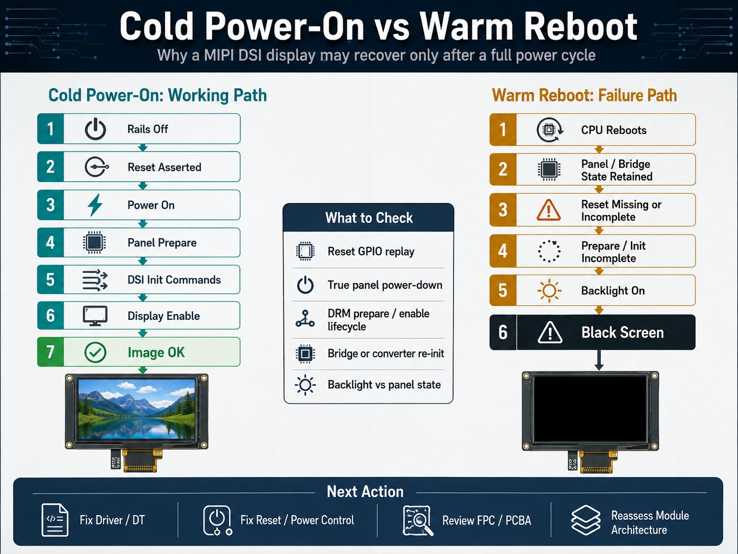
If the reset GPIO does not execute correctly, fix the software or board configuration. If panel initialization is not replayed after reboot, correct the driver lifecycle or initialization path.
Hardware changes become relevant only when the required control path cannot be implemented reliably with the existing architecture.
For example:
-
If reset or enable is required but the signal is not routed, review the FPC or display assembly.
-
If the carrier board cannot independently control a required rail or bridge reset, review the PCBA.
-
If the current display architecture creates unnecessary dependencies around conversion, control, or software maintenance, evaluate a different module architecture.
-
If the electrical system works but connector retention or FPC routing changes behavior after final assembly, investigate the mechanical integration.
The important distinction is between a software state problem and an architecture problem.
Do not redesign the carrier board when the evidence points to a missed software reset. Conversely, repeated software workarounds cannot replace a control signal that is absent from the hardware path.
Which Integration Level Fits a Production Embedded HMI?
A standard touch display module can remain appropriate when the host interface matches, the required reset and power controls are available, and the driver lifecycle can be maintained on the target platform.
A custom display assembly becomes more relevant when the production system needs a different FPC, connector arrangement, touch stack, interface arrangement, or mechanical format.
A modular HMI or embedded display architecture may be more appropriate when the project combines the Linux platform, display, touch, interface electronics, and GUI environment into one integration problem.
Kadi’s embedded Linux display solutions category currently includes Linux- and FreeRTOS-oriented products and references LVGL and Qt development environments, reflecting a system-integration layer beyond a bare TFT panel.
More broadly, Kadi Display organizes its current product offering across TFT displays, touch modules, Raspberry Pi displays, embedded solutions, monitors, and customized display options.
The appropriate level depends on the exact host, display, software stack, carrier design, and production constraints.
What Information Should You Prepare Before Requesting Display Integration Support?
If the reboot problem reveals that the existing display architecture needs modification, prepare information that defines both the working and failing conditions.
Useful project information includes:
-
host processor, SoC, or SoM model;
-
carrier-board model or revision;
-
display/module part number;
-
display size and resolution;
-
MIPI DSI lane configuration, if available;
-
OS, BSP, and kernel version;
-
panel-driver and Device Tree information, if known;
-
behavior after a full power-on;
-
behavior after warm reboot;
-
whether complete power removal restores the image;
-
backlight status after reboot;
-
touch status after reboot;
-
available reset, enable, or power-sequence information;
-
panel datasheet or pinout, where available;
-
mechanical drawing if an FPC or module change is under consideration.
These details make it easier to separate a reset or software-lifecycle problem from an issue that may require a different display assembly or system architecture.
Conclusão
When a MIPI DSI display works after power-on but goes black after warm reboot, debug the difference between those two startup paths. Check whether panel reset occurs, whether the display reaches the required off state, whether the Linux DRM lifecycle runs correctly, and whether any bridge or controller is reinitialized.
If the evidence points to a different FPC, control path, display module, carrier-board interface, or embedded display architecture, you can contato Kadi Display with the host platform, display model, OS/BSP/kernel, cold-boot and warm-reboot behavior, backlight/touch status, and available reset or power information to discuss suitable display options. Kadi’s contact page accepts technical questions and custom-display requests.
Reset behavior, sequencing, initialization, and compatibility should be verified against the exact display, host, carrier-board design, and software configuration.
FAQ
Why does my MIPI DSI display work after a power cycle but not after reboot?
A complete power cycle and a warm reboot may leave the display system in different states. The panel, bridge, regulator, or reset path may not return to the same initial condition during reboot. Compare reset, panel power-down, driver lifecycle, and reinitialization before changing display parameters.
Does a black screen after warm reboot mean the MIPI DSI panel is defective?
Not by itself. If the same module repeatedly works after full power-on, first investigate whether the reboot path correctly resets, powers down, and reinitializes the display. Hardware faults should be reconsidered if those checks do not explain the behavior.
Why can the backlight be on while the screen remains black after reboot?
The backlight can be controlled separately from panel initialization and the MIPI DSI video path. A lit backlight therefore does not show that the panel has completed reset, initialization, DSI attachment, and video enable.
Should I change the FPC if a manual reset restores the image?
A manual reset restoring operation points first toward reset or lifecycle behavior. Changing the FPC becomes relevant if the production interconnect does not route the required reset, enable, or control signals correctly.
When should I consider a different display module or embedded solution?
Consider a different integration approach when the problem is broader than one reset or driver fix—for example, when the production host needs a different control architecture, FPC arrangement, converter/interface path, touch integration, or mechanical format.
PRIVENTE
MIPI DSI Works at Low Refresh Rates but Fails at 60 Hz: A Practical Troubleshooting Workflow
NEXTO
MIPI DSI Image Is Present but Corrupted: Pixel Format, Timing, Driver, and Signal-Path Checks
Deixe um comentário

Recent Blog & News
- Industrial LCD EOL: What Happens from Pre-Announcement to Replacement Mass Production?
- Electronic Component Obsolescence Management for Industrial Displays: An OEM Guide
- How to Develop a Production Ready Custom Display Assembly TFT Module Touch Cover Glass FPC Bonding and Mounting
- 15 Pin vs 22 Pin Raspberry Pi DSI Connectors Cable Pinout and Compatibility
- Native MIPI DSI vs LVDS or HDMI Bridge: An OEM Display Architecture Decision Guide

