Главная
-
Блог & Новости
-
LCD Prototype Passed but Pilot Units Fail: A Display Integration Isolation Workflow
LCD Prototype Passed but Pilot Units Fail: A Display Integration Isolation Workflow
2026-09-17
00:00
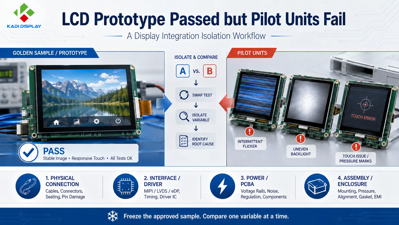
When an LCD prototype works but production fails during a pilot build, the display panel may not be the root cause. Differences in module revisions, FPC insertion, PCBA power, firmware, touch grounding, fastener load, or enclosure tolerances can turn a working prototype into inconsistent pilot units. Preserve the approved prototype as a golden sample, freeze the configuration, and compare passing and failing units one variable at a time. The objective is to locate the failure before changing the display, board, or mechanical design.
What Changed Between the Prototype and the Pilot Build?
A successful prototype confirms that one display configuration can operate. Pilot production asks a different question: can multiple units reproduce the same image, touch response, and mechanical fit under a controlled assembly process?
Start by documenting the symptoms. Useful distinctions include:
-
No image versus intermittent image loss
-
Flicker versus unstable backlight brightness
-
Touch failure versus ghost touches
-
Pressure marks, light leakage, or active-area misalignment
-
Normal operation outside the enclosure but failure after installation
-
Failures concentrated in one component batch, PCBA revision, or assembly station
Compare the golden sample with affected units. Record the LCD and touch part numbers, revisions, FPC and connector specifications, PCBA revision, firmware, Device Tree, power settings, cover glass, gasket, bracket, enclosure, and assembly sequence.
An undocumented prototype modification can matter. A hand-reworked cable, different initialization file, extra grounding tape, or looser fastener may explain why the engineering sample passes while nominally identical pilot units do not.
Quick Check: Does the Failure Follow the Module, Host, or Assembly?
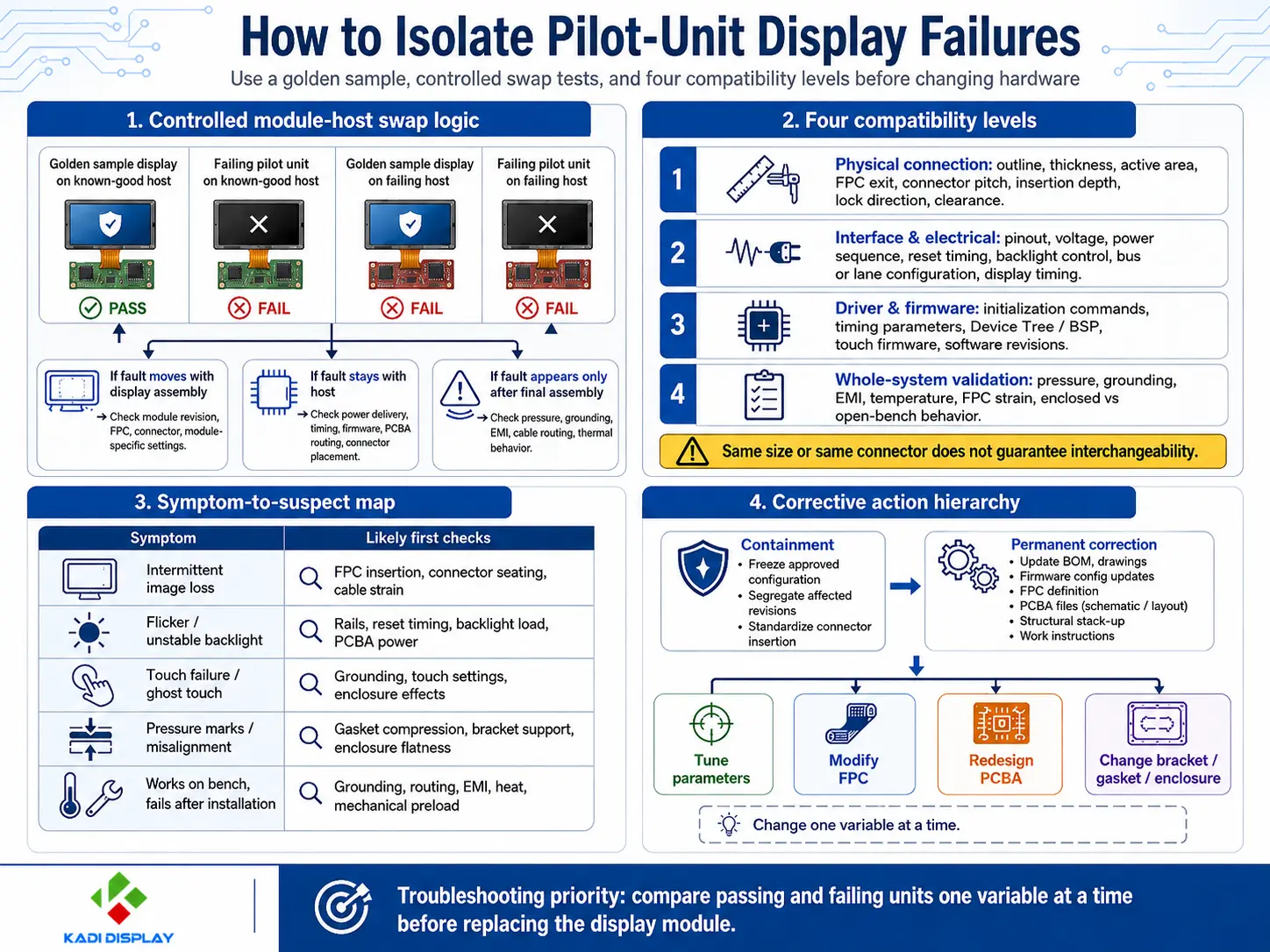
A controlled swap test can narrow the problem before a redesign begins. Power down the equipment and follow the relevant module and connector handling requirements. Then test a failing display assembly on a known-good host and a known-good display assembly on a failing host.
Change only one item at a time:
-
Display or touch module
-
FPC or interface cable
-
Controller or main PCBA
-
Firmware and display configuration
-
Bracket, gasket, or enclosure
-
Power supply and backlight settings
If the symptom moves with the display assembly, investigate its revision, specification, connector, FPC, or module-dependent settings. If it stays with the host, inspect power delivery, timing, firmware, PCBA routing, and connector placement. If the failure appears only after final assembly, mechanical preload, grounding, cable routing, EMI, or thermal behavior becomes more likely.
Randomly swapping several parts at once may restore operation without identifying which variable caused the failure.
Build a Display Integration Fault Tree
A pilot-production fault tree should separate four compatibility levels.
Physical Connection
Verify the module outline, thickness, active-area location, FPC exit, connector pitch, contact orientation, pin 1, insertion depth, lock direction, cable reach, and assembly clearance.
The same diagonal size or connector does not establish physical interchangeability.
Interface, Driver, and System Compatibility
Check the interface and electrical requirements separately: pinout, voltage levels, power sequence, reset timing, backlight control, lane or bus configuration, and display timing. For high-speed interfaces such as MIPI DSI or LVDS, cable construction, routing, reference continuity, and host configuration also matter.
Driver support is another layer. Compare initialization commands, timing parameters, Device Tree, BSP, touch firmware, and software revisions.
Finally, validate the complete system. A module that works on an open bench may behave differently after installation because of pressure, grounding, EMI, temperature, or FPC strain. Full compatibility requires physical, electrical, software, and assembled-system verification.
Test Pilot Units Without Changing Multiple Variables
Create a small test matrix using representative passing and failing units. The limits and acceptance criteria should come from the selected LCD, touch controller, connector, host platform, and product requirements.
| Test | Evidence to Collect | Likely Next Step |
|---|---|---|
| Golden-sample comparison | Part, drawing, BOM, PCBA, and firmware revisions | Freeze or correct the configuration |
| Controlled module-host swap | Whether the fault follows the module or host | Investigate the corresponding subsystem |
| Power and reset measurement | Voltage drop, startup sequence, reset, and backlight interaction | Adjust documented settings or review the PCBA |
| FPC and connector inspection | Insertion depth, lock position, strain, abrasion, and alignment | Improve assembly control or modify the FPC |
| Open versus enclosed test | Effect of pressure, grounding, routing, and heat | Review the display stack-up and structure |
| Touch test under system load | Noise or ground sensitivity during backlight and processor activity | Review grounding, touch settings, PCBA, or enclosure |
Record the unit, test configuration, symptom, and result for every change. This makes it possible to build a failure distribution by module revision, assembly station, or system configuration instead of relying on isolated observations.
Why Pilot Units Fail After a Successful Prototype
Component and configuration drift is one common cause. The pilot build may use a different LCD revision, touch controller firmware, connector, adhesive, or approved alternate component. Even when the headline specifications match, differences in outline, FPC position, pinout, initialization, brightness, or environmental rating can affect the system.
FPC and connector problems are also highly sensitive to production assembly. Incomplete ZIF insertion, an inaccessible lock, cable twist, an unsuitable bend near the stiffener, or enclosure-induced tension can create intermittent image or touch faults.
Power and PCBA differences should be checked when failures occur during startup, high brightness, or processor activity. Relevant evidence may include display-rail voltage, reset timing, backlight load, ground reference, connector placement, and high-speed signal routing. Parameter changes should remain within the component specifications and should not be used to conceal inadequate electrical margin.
Mechanical stack-up problems often appear only after assembly. Excessive gasket compression, uneven bracket support, enclosure flatness, fastener sequence, adhesive placement, or insufficient FPC clearance can create pressure marks, glass stress, connector movement, or touch instability. Kadi’s guide to industrial display stack-up design provides additional context for coordinating LCD, touch, PCB, FPC, and enclosure interfaces.
Fix the Confirmed Cause and Verify Repeatability
Separate containment from permanent correction. Containment may restore the approved configuration, segregate affected revisions, standardize connector insertion, or add an inspection point.
A permanent correction should update the controlled BOM, drawings, firmware configuration, FPC definition, PCBA files, structural stack-up, work instructions, and acceptance criteria affected by the finding.
Repeat the verification on fully assembled units under application-relevant power, temperature, touch, and operating conditions. A successful open-bench retest confirms less than a test performed in the intended system configuration.
When to Tune Parameters, Replace the Module, or Redesign Hardware
Tune timing, reset, power, backlight, touch, or firmware parameters when the hardware is verified and the failure follows a documented configuration difference. Confirm every setting against the module and host specifications.
Replace or reselect the module when the existing display cannot meet the required interface, optical, mechanical, environmental, or lifecycle conditions. A replacement still requires checks at all four compatibility levels.
Modify the FPC when evidence points to cable reach, bend stress, connector orientation, pinout, insertion access, or high-speed routing constraints. FPC changes must be evaluated with the connector, host layout, assembly sequence, and enclosure.
Redesign the PCBA when measurements identify insufficient power margin, problematic connector placement, signal integrity, grounding, protection, or interface limitations.
Change the bracket, gasket, or enclosure when the fault appears after installation and follows pressure, alignment, cable routing, grounding, or thermal behavior. The structure should support the display without loading sensitive glass, active areas, or driver regions.
Where several interfaces must change together, customized display solutions may provide a clearer boundary than sourcing the LCD, touch panel, cover glass, FPC, controller, and mechanical parts independently.
Choose the Appropriate Display Solution Level
A standard Touch Display Module remains appropriate when its physical, electrical, firmware, and environmental requirements already fit the device and the confirmed issue is assembly control.
A modified module may be more suitable when the project requires a different FPC, connector, touch panel, cover glass, bonding method, or interface adaptation. A Custom Display Assembly becomes relevant when optical, electrical, and mechanical interfaces need to be controlled as one configuration.
When the project also requires a controller board, host adaptation, power architecture, or defined mechanical mounting, embedded display solutionс or a Modular HMI Solution may reduce the number of interfaces the OEM must manage. The appropriate level depends on the application, host platform, validation boundary, and approved specification.
Кади Дисплей should therefore be considered in the context of the required integration level, not only as a source for a bare TFT panel.
Prepare the Technical Package for an RFQ or Integration Review
A useful review package should include:
-
Application and host platform
-
Operating system and firmware revision
-
Current display and touch specifications
-
Size, resolution, interface, and brightness requirement
-
FPC and connector drawings
-
Relevant power and reset information
-
Mechanical or stack-up drawing
-
Golden-sample and pilot-unit revisions
-
Clear fault photos or videos
-
Expected project quantity
These materials help determine whether the next step is a parameter correction, module change, custom assembly, or broader system modification.
Вывод
When an approved LCD prototype and pilot units behave differently, freeze the configuration before replacing parts. Trace whether the fault follows the module, host, assembly process, or enclosure, then make the smallest change supported by evidence.
For a project-level review, readers can контакт Kadi Дисплей with the host platform, display specification, interface, FPC and connector drawings, mechanical drawing, fault photos, and expected quantity. The review can then focus on the display-related solution level relevant to the project.
Часто задаваемые вопросы
Does a Working LCD Prototype Prove the Display Is Ready for Production?
No. It proves that one configuration can work. Production readiness also depends on controlled component revisions, tolerances, firmware, assembly procedures, and complete-system verification.
Should the LCD Module Be Replaced First?
Replacement should follow evidence. A controlled module-host swap can show whether the failure follows the display assembly or remains with the PCBA, firmware, power system, or enclosure.
Can Two Displays With the Same Connector Be Interchangeable?
Not necessarily. Connector pitch and pin count are only physical details. Pinout, voltage, interface timing, initialization, driver support, FPC geometry, optical alignment, and system validation must also be checked.
Why Does the Display Fail Only After Enclosure Assembly?
Installation may introduce gasket compression, frame stress, FPC tension, connector movement, grounding changes, EMI coupling, or heat accumulation. Compare open and enclosed operation while keeping the electrical and software configuration unchanged.
Предыдущий
MIPI DSI Display Works at Room Temperature but Fails After Warm-Up: A Troubleshooting Workflow
Следующая
How to Choose an LCD Controller Board: Architecture, EDID, Timing and Latency
Оставить комментарий

Последние блоги и новости
- MIPI DSI Display Works at Room Temperature but Fails After Warm-Up: A Troubleshooting Workflow
- LCD Prototype Passed but Pilot Units Fail: A Display Integration Isolation Workflow
- How to Choose an LCD Controller Board: Architecture, EDID, Timing and Latency
- Industrial Display RFQ Checklist: Build a Supplier-Ready Evidence Package
- Industrial LCD Drop-In Replacement Checklist: From Hard Stops to Release Evidence
Блог и новости