


Серийный интерфейс дисплея MIPI (DSI)
2025-09-12
11:50
Уровни интерфейса и пакетов
Уровень интерфейса
Существуют два уровня МИПИ связи, которые разделены на уровень интерфейса и уровень пакета. Низкий уровень связи осуществляется на уровне интерфейса. Уровень интерфейса используется для указания настроек мощности и скорости дисплея. Он поддерживает такие режимы, как низкая мощность, сверхнизкая мощность и высокая скорость. Эти режимы определяют, как система переходит между отправкой команд и данными изображения.
Уровень интерфейса состоит из различных состояний, которые управляют данными дифференциально как для режима высокой скорости, так и для режима низкой мощности. Переключение между этими состояниями управляется путем движения положительных и отрицательных полос в соответствии с определенными кодами состояния. Уровень интерфейса определяется приложением и возможностями хост-процессора.
Уровень пакета
Коммуникация на уровне пакетов используется при отправке данных изображения на дисплей в коротких (4 байта) или длинных (от 6 до 65 541 байт) пакетах. Этот слой обрабатывает операции более высокого уровня, такие как передача команд, пикселей изображения и проверка ошибок.
Уровень пакетов: короткие и длинные пакеты
Пакеты отправляются в определенной последовательности для указания размера пакета и кодов исправления ошибок. Короткие пакеты могут быть отправлены для команд, которые не требуют данных. Они обычно используются для контроля регистров. Более длинные пакеты могут быть использованы для отправки команд с несколькими байтами данных и данных изображения.
Первый байт - это байт идентификатора данных, который включает два бита для идентификатора виртуального канала. Это позволяет управлять до четырех периферийных устройств через один MIPI DSI Автобус. Количество слов для длинных данных указывает, сколько байтов данных будет следовать.
Уровень пакета: исправление ошибок
Контрольная сумма и байты коррекции ошибок определяются контроллером для конкретных функций. Эти механизмы обеспечивают надежную передачу по высокоскоростным дифференциальным полосам, что имеет решающее значение в приложениях в реальном времени, таких как потоковое видео.
Режимы видео и команды
Режим команды
Командный режим может использоваться для дисплеев, которые имеют доступ к памяти буфера кадров для отображения изображений. Этот режим позволяет записывать непосредственно в дисплейные регистры с помощью коротких или длинных пакетов. Режим команды — это то, что обычно наблюдается с интерфейсами, такими как SPI, параллельный MCU 8080/6800 и контроллеры дисплея I2C.
Этот режим обеспечивает гибкость в операциях с низкой мощностью, поскольку он не требует непрерывного потока пикселей. Он подходит для дисплеев с встроенной памятью, где изображения могут храниться временно.
Режим видео
Режим видео - это когда данные отправляются в виде потока пикселей в реальном времени. Этот режим полагается на хост-процессор для обеспечения постоянного потока данных изображения, который постоянно обновляется. Поскольку на таких дисплеях нет кадрового буфера, вся пиксельная информация должна передаваться в прямом эфире.
Режим видео: пакетная структура пиксельных данных RGB-565
Коммуникация на уровне пакетов в видеорежиме отправляется в виде постоянного потока пикселей в определенной последовательности. События синхронизации определяют активные области, похожие на интерфейсы RGB. События синхронизации указывают начало и конец синхронизации, подобно интерфейсу RGB, чтобы представлять активную область пиксельных данных.
События синхронизации отправляются в коротких пакетах, которые указывают местоположение и длину веранды. Эта структура позволяет точно контролировать время без переключения между режимами низкой мощности и высокой скорости во время каждого кадра.
Режим видео: Режим взрыва против режима без взрыва
В режиме взрыва пиксельные данные сжаты, чтобы зарезервировать время для того, чтобы уровень интерфейса вернулся к низкой мощности. Режимы без взрыва зависят от синхронизационных импульсов или событий. Режим синхронизации импульсов без разрыва потребует определения ширин импульсов дисплея.
Режим взрыва помогает оптимизировать потребление энергии при сохранении высокоскоростной передачи. Режимы без взрыва предлагают большую гибкость в времени, но могут потреблять больше энергии из-за непрерывной сигнализации.
Соображения
Режим видео
Работа дисплея в режиме видео требует отправки пакетов в постоянном потоке с использованием высокоскоростного уровня интерфейса. Хотя это обеспечивает рендеринг в режиме реального времени, это также значительно увеличивает энергопотребление системы. Процессор хоста должен быть в состоянии общаться с высокоскоростной скоростью передачи данных и, как следствие, потребовать большей мощности для работы в высокоскоростном режиме.
Внешняя память
Внешняя память может использоваться для хранения буфера кадров удаленно от дисплея. Однако это создает проблемы, такие как ограничения времени и дополнительное потребление энергии. Буфер кадра должен постоянно обновляться, чтобы избежать меркания и потери изображения.
Эффективность затрат
Дисплейы, которые не содержат внутреннего расположения памяти кадрового буфера, часто дешевле. Эта экономия затрат переносит ответственность, такую как управление памятью или синхронизация, на системные контроллеры. Есть два варианта, когда внутренняя оперативная память не предоставляется дисплеем. Процессор хоста может обеспечить память дисплея, если ее достаточно для поддержки графики высокого уровня. Другим вариантом является использование режима видео, в котором данные изображения передаются потоково и не хранятся.
Часто задаваемые вопросы
Q1: Что делает MIPI DSI превосходным для встроенных систем?
Дисплейы MIPI DSI имеют преимущество графики высокого уровня при снижении сложности маршрутизации сигнала, конструкции PCB и затрат на оборудование.
Q2: Может ли MIPI DSI работать при низкой мощности?
Интерфейс MIPI DSI может работать при очень низкой мощности, чтобы сохранить срок службы батареи.
Q3: Сколько периферийных устройств может управлять MIPI DSI?
MIPI DSI может управлять до четырех периферийных устройств с помощью этого виртуального идентификатора канала.
Q4: Что происходит, если мой дисплей не имеет внутренней оперативной памяти?
Вы должны использовать режим видео или выделить внешнюю память, способную поддерживать непрерывные частоты обновления.
индивидуальный дисплей DSI MIPI от дисплея Kadi
Кади Дисплей специализируется на предоставлении индивидуальных решений для дисплея mipi, разработанных вокруг потребностей клиентов. В более чем 20 лет опыта в отрасли дисплея, мы обнаружили, что большое количество клиентов нуждаются не только в TFT-ЖК, но и в полном решении дисплея, интегрирующем сенсорный, PCBA и корпус;
Их завод занимает площадь более 5000 квадратных метров с специальными производственными линиями для сборки LCM / TP / BONDING. Мы используем уникальные преимущества цепочки поставок Шэньчжэня, чтобы предоставить клиентам быстрый набор дисплейных решений, включая индивидуальные подсветки, подсветки, интерфейсы, такие как TTL / LVDS / MIPI / EDP / DP / HDMI / Type-C / VGA / USB-A.
Kadi предлагает услуги оптического соединения с использованием клеев OCA/OCR, которые повышают читаемость под солнечным светом, устраняя воздушные пробелы. Их линейка продуктов включает в себя ЖК-дисплеи IPS TFT с широкими углами обзора до 178 градусов, что идеально подходит для промышленных приложений, требующих отличной цветовой верности.
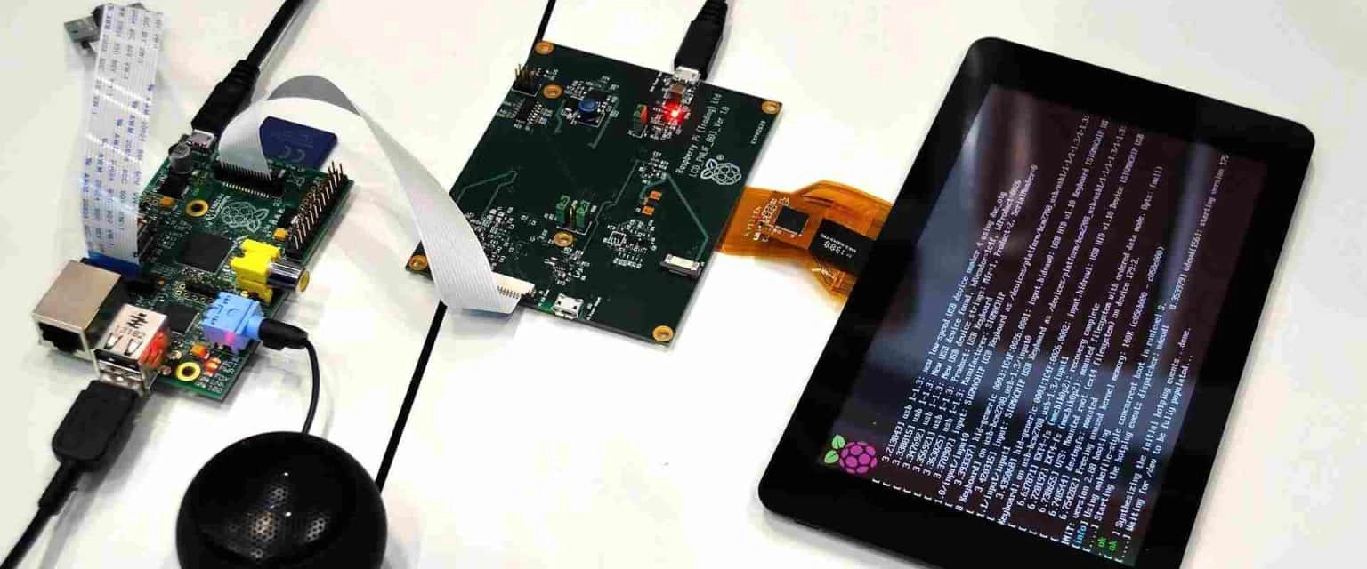
Для пользователей Raspberry Pi или встроенных разработчиков, ищущих компактные дисплеи mipi, Kadi также предоставляет модули, такие как их 5-дюймовый дисплей DSI MIPI 800 × 480, специально разработанный для интеграции Raspberry PI.
Если вы’ Разработка носимых технологий или автомобильных приборных панелей, требующих солнечных панелей или требующих полноценной настройки от дизайна стеклянной крышки до макета FPC - Kadi поставляет профессиональные решения для дисплея mipi, адаптированные именно к вашим потребностям проекта. Свяжитесь с Kadi Display сегодня.
Предыдущий
PWM (модуляция ширины импульса) светодиодная подсветка для ЖК-дисплеев
Следующая
Учет температуры для дисплеев
Оставить комментарий

Последние блоги и новости
Блог и новости
-
 TN против IPS2024-7-9
 -
 TN против IPS2024-7-9