




MIPI DSI LCD Platform Selection Guide: Match the Panel to the Host
2026-07-31
16:33
MIPI DSI LCD Platform Selection Guide: Match the Panel to the Host
Native DSI, bridge paths, lane limits, software support, and sourcing evidence for ESP32-S3, STM32, Rockchip, and Raspberry Pi
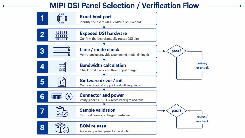
A MIPI DSI LCD is viable only when the host, PHY, lane configuration, pixel timing, panel initialization, connector, and software stack all agree. This guide gives hardware engineers and buyers a platform-first method for choosing a panel without relying on family-level assumptions or marketing shorthand.
Why Platform-Level DSI Support Matters More Than Panel Specs
Direct answer — Choose the host and software path first. A matching connector and sufficient theoretical bandwidth do not compensate for a missing DSI host, unsupported lane configuration, absent panel driver, or unavailable initialization sequence.
Related Kadi Display reference: Kadi Display’s platform-level MIPI support guide.
Engineers shopping for a MIPI DSI LCD panel often begin by comparing resolution, brightness, and price across display datasheets. That approach frequently leads to a costly dead end: a panel arrives, the team discovers their platform cannot drive it natively, and the project schedule absorbs weeks of bridge chip integration or panel re-selection.
The distinction has real cost and timeline impact. A platform with native MIPI DSI output can drive a DSI panel directly through its integrated D-PHY transmitter. A platform without native DSI requires a bridge IC (such as the SSD2828 from Solomon Systech), adding BOM cost, PCB area, power consumption, and an additional firmware initialization sequence that must be debugged independently from the panel itself.
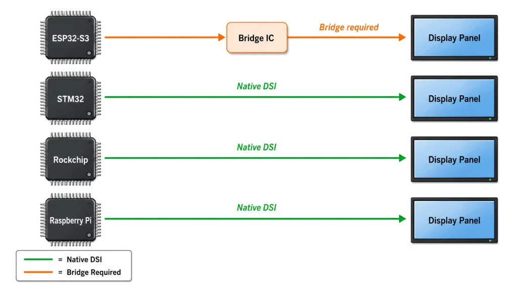
ESP32-S3: No Native MIPI DSI — Bridge Chip Required
The ESP32-S3 provides RGB and Intel 8080-style LCD paths but does not integrate a native MIPI DSI host. A DSI-only panel therefore requires a validated bridge architecture or a different host. The newer ESP32-P4 is a separate device family and should not be used to infer ESP32-S3 capability.
For ESP32-S3, an RGB panel is usually the lowest-risk choice for 800×480-class HMIs. If a bridge is necessary, confirm the bridge input format, output lane count, supported DSI mode, maximum lane rate, reference clock, initialization path, and production availability before selecting the panel.
Do not approve a bridge from a headline lane-rate number. Calculate payload from complete horizontal and vertical timing, pixel format, and refresh rate; then include the transport method and the bridge vendor’s required margin. A result within only a few percent of the advertised maximum is a risk flag, not a comfortable design.
STM32: Native DSI on Select Families — Check the Specific Part Number
Part-number gate — “STM32H7” or “STM32F4” is not a sufficient compatibility statement. Freeze the exact orderable part, package, reference manual, lane count, maximum lane rate, and memory/display subsystem before ordering panels.
Related Kadi Display reference: Kadi Display’s MIPI, RGB, and LVDS interface comparison.
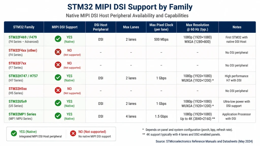
STMicroelectronics offers native MIPI DSI host support on several STM32 families, but not all. This is the most common source of confusion in STM32 MIPI projects.
STM32 families with native MIPI DSI:
-
STM32F469/F479: the integrated DSI host supports up to two D-PHY data lanes; the usable mode and lane rate must be checked against the exact part and clock configuration.
-
STM32H747/H757: two-lane DSI host implementations are available on specified parts; verify the exact package, LTDC path, maximum lane rate, memory bandwidth, and software example.
-
STM32U599/U5A9 and related qualified variants: check the exact datasheet and reference manual because DSI support is not a family-name guarantee.
-
STM32MP1-class devices: application-processor DSI capability depends on the exact MPU, board routing, Linux driver, and panel description.
A native DSI host does not remove interconnect work. Follow the host and panel reference stack-up, impedance target, breakout geometry, return-path, skew, connector, and flex guidance. Avoid a universal length-match number; the allowable budget depends on lane rate and the complete channel.
Rockchip: Native Multi-Lane DSI Across the Product Line
Rockchip SoCs frequently integrate one or more MIPI DSI hosts, but controller count, lane count, lane rate, supported modes, and display routing vary by part and package. Confirm the exact technical reference manual, schematic, board device tree, and vendor kernel support. Do not infer that every SoC or board exposes every DSI controller.
Raspberry Pi: Native 2-Lane DSI with Ecosystem Constraints
Raspberry Pi DSI connectivity is model-specific. Full-size boards from the B+ generation onward generally expose a display connector, while the Zero family does not. Raspberry Pi 5 uses two 22-way combined camera/display ports; earlier full-size boards typically use a 15-way display connector. Compute Modules expose different routing through their carrier designs.
For industrial deployment, select the exact Raspberry Pi or Compute Module, carrier board, cable, panel driver, and power architecture together. A connector being present does not guarantee that an arbitrary third-party DSI panel has an upstream driver or compatible initialization sequence.
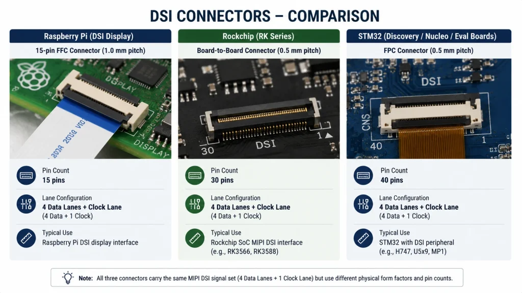
Platform Selection Decision Matrix
The following matrix distills Sections 2–5 into a single reference for teams at the platform selection stage:
Panel Specification Alignment — Matching DSI Lanes to Panel Requirements
Once you know your platform’s native DSI capability, verify that the target panel’s bandwidth requirement fits within it.
First estimate pixel clock from Htotal × Vtotal × frame rate. Multiply by bits per pixel and divide by active data lanes to obtain raw payload per lane. Then apply the host-controller method for packet overhead, video mode, and engineering margin; do not use a universal 1.1 multiplier as a substitute for the controller documentation.
Practical Sourcing — What to Verify Before Committing to a Panel
Release package — Approve the panel only when the exact datasheet, initialization data, lane/mode configuration, pinout, connector drawing, power sequence, sample result, and software ownership are stored with the BOM.
Related Kadi Display reference: Kadi Display’s Raspberry Pi MIPI DSI connection guide.
Hardware teams lose weeks when they order samples based purely on resolution and brightness without confirming interface-level compatibility. Verify these before ordering:
Exact DSI lane count and data rate — a datasheet listing ‘MIPI DSI’ without specifying lanes is incomplete.
Panel initialization sequence — every panel requires vendor-specific register writes. Without this, you cannot bring up the display.
DSI mode (Command vs. Video) — most industrial panels use Video Mode. Some small AMOLED panels use Command Mode, which changes the firmware architecture significantly.
Physical connector and pinout — MIPI DSI has no standard connector. Pinouts vary between suppliers even at the same resolution.
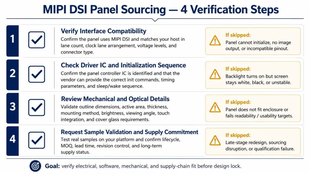
A useful compatibility review separates capability from exposure. A silicon block may support four data lanes while the chosen package or board routes only two. Likewise, a carrier can expose a DSI connector without providing the regulator, reset, backlight, or touch connections expected by the target module.
Treat vendor software as configuration evidence, not as a substitute for the panel datasheet. Record who owns the panel driver, how it will be updated with the operating system, and how the system will recover from power interruption or failed initialization in production.
Start the selection worksheet with three exact identifiers: the orderable host part, the production board revision, and the display module revision. Family names are discovery terms, not release evidence. The package determines which pins exist, the board decides which pins are routed, and the module revision can change the controller, FPC, or initialization data while keeping the same marketing name.
Next, separate native capability from bridge feasibility. A bridge adds two independent interfaces, at least one configuration bus, clocking, power rails, reset behavior, and another lifecycle dependency. The host must generate the bridge input timing, the bridge must generate a DSI mode accepted by the panel, and firmware must initialize both devices in a deterministic order. That architecture can be valid, but it deserves its own risk register and prototype plan.
Memory bandwidth belongs in the platform decision even when the DSI link itself fits. A microcontroller may have a two-lane host yet lack enough sustained memory service for a large framebuffer, graphics acceleration, and application workload. An application processor may have abundant bandwidth but require a maintained Linux panel driver. Compare the whole display pipeline: image source, framebuffer, compositor, host controller, PHY, interconnect, and panel.
Software evidence should be graded. An upstream kernel driver with a reviewed device-tree binding has lower maintenance risk than a vendor patch tied to one old kernel. A complete bare-metal example with source and named panel revision is stronger than a register dump without comments. A binary blob that cannot be rebuilt or traced should trigger an ownership and lifecycle discussion before the hardware is frozen.
Connector compatibility deserves a separate sign-off. MIPI DSI does not standardize the module connector, pinout, power pins, touch bus, or backlight path. Check pin 1, exposed-contact side, pitch, circuit count, insertion thickness, lane polarity, grounds, and the placement of reset and enable signals. A mechanically mating FPC can still place power onto a signal pin or swap a differential pair.
Prototype validation should cover more than first light. Exercise cold and warm start, repeated power cycling, software reset, suspend/resume where applicable, maximum and minimum brightness, representative graphics load, cable handling, supply corners, and temperature. Read host errors during the test. A panel that shows a clean image while accumulating lane or CRC errors has not passed.
Finally, create a substitution rule. If procurement wants an alternate panel, host, connector, or bridge, define which evidence must be repeated. A new panel with the same size and resolution can change timing, lane count, controller, initialization, FPC pinout, touch controller, and backlight. Treat those changes as an engineering evaluation, not a purchasing equivalence.
Evidence Package and Release Control
Before releasing a mipi dsi platform compatibility design, convert the article’s guidance into a requirements matrix. Give every requirement an owner, source, revision, unit, tolerance, verification method, sample quantity, and acceptance rule. This prevents an informative article from being mistaken for a product specification and makes unanswered questions visible while changes are still inexpensive.
Separate documented limits from planning assumptions. A datasheet value, vendor application note, calculated estimate, measured prototype result, and internal design target do not have the same authority. Label each one. When a value is only representative, record the condition that would make it change and identify the exact document or test that must replace it before production release.
Use production-intent samples for the final decision. Evaluation boards, hand-selected cables, open-bench wiring, laboratory power supplies, and debug firmware can hide tolerance and assembly problems. Repeat the relevant checks with approved component alternatives, final connector and flex routing, enclosure constraints, released clock and power settings, and the intended manufacturing process.
Define failure evidence before testing. Decide which measurements, logs, images, waveforms, error counters, and sample identifiers will be collected when a unit fails. If the team records only pass/fail, intermittent or environment-dependent behavior becomes difficult to reproduce. Good failure evidence should distinguish component, interconnect, firmware, assembly, and system-level causes without immediately blaming the most visible part.
Control changes after approval. A supplier substitution, firmware update, timing adjustment, coating change, connector revision, PCB stack-up change, or new assembly site can invalidate earlier evidence. The change process should state which reviews and tests repeat, who approves deviations, how old and new lots remain traceable, and what field or incoming data will be monitored after release.
For publication, keep MIPI DSI LCD terminology consistent with the engineering record. Do not turn a conditional finding into a universal rule to make the prose sound decisive. Search engines and answer systems reward clear direct answers, but technical credibility depends on preserving scope, units, test conditions, and uncertainty. A qualified answer is more useful than a confident number that belongs to another component.
Complete the review with an independent reader. Ask someone who did not write the article or perform the first test to reproduce one calculation, locate each cited requirement, and challenge the main conclusion. Close any gap between the published guidance and the controlled engineering documents. This simple review often catches unit mistakes, stale revisions, hidden assumptions, and claims that cannot be verified from the evidence provided.
Archive the released package in a location shared by engineering, quality, procurement, and support. Include the article revision, approved drawings, links, calculations, test records, known limitations, and decision owner. That package gives later teams enough context to investigate a field issue or approve a controlled change without rebuilding the original reasoning.
FAQ: MIPI DSI Platform Selection
Can a four-lane host always drive a two-lane panel?
Only if the host controller, board routing, panel controller, and driver all support two-lane operation at the required per-lane rate. Maximum lane count does not guarantee every lower-lane configuration.
Does sufficient bandwidth prove compatibility?
No. The PHY version, lane mapping, timing, pixel format, operating mode, command sequence, connector, power sequence, and driver must also match.
Is ESP32-S3 a native MIPI DSI platform?
No. It supports RGB and Intel 8080-style LCD interfaces, among others, but not a native DSI host. A DSI-only panel needs a bridge or different host.
How should STM32 DSI support be verified?
Use the exact part-number datasheet and ST’s DSI application note. For example, STM32F469/F479 supports up to two D-PHY data lanes; do not repeat the common one-lane claim.
What is the safest sourcing question?
Ask the supplier to provide the exact panel datasheet, tested initialization sequence, lane/mode settings, connector pinout, and a host-specific sample result before purchase approval.
Engineering source notes
Related Kadi Display reference: MIPI DSI platform support across STM32, Raspberry Pi, and ESP32.
Related Kadi Display reference: industrial display interface selection for MIPI, RGB, and LVDS.
Related Kadi Display reference: connecting a MIPI DSI LCD to Raspberry Pi.
Primary technical references: ST AN4860 DSI host application note; STM32F469 datasheet; Raspberry Pi display documentation.
Product Reference & Engineering Support — For industrial TFT LCD modules, interface documentation, application review, sample validation, and OEM/ODM support, contact Sales@sz-kadi.com or review the Kadi Display product range.
Product range: industrial TFT LCD modules and custom display solutions.
Representative engineering guidance only. Verify host capabilities, lane rates, timing, initialization, connector, power, and software support against the exact orderable device, board, and panel documentation. Third-party product names and trademarks belong to their owners.
Предыдущий
MIPI DSI Display Bring-Up Checklist: Eight Evidence Gates
Следующая
Common ZIF Connector Problems in Industrial Touchscreens and How to Fix Them
Оставить комментарий

Последние блоги и новости
- MIPI DSI Display Works at Room Temperature but Fails After Warm-Up: A Troubleshooting Workflow
- LCD Prototype Passed but Pilot Units Fail: A Display Integration Isolation Workflow
- eDP LCD Panel Integration: Power, AUX, Link Training, Video and Backlight
- How to Choose an LCD Controller Board: Architecture, EDID, Timing and Latency
- Industrial Display RFQ Checklist: Build a Supplier-Ready Evidence Package
Блог и новости
-
 TN против IPS2024-7-9
 -
TN против IPS2024-7-9

