




Startseite
-
Blog & Neuigkeiten
-
ESP32-S3 RGB Display with GT911 and LVGL: A Practical Guide for Kiosk and HMI Applications
ESP32-S3 RGB Display with GT911 and LVGL: A Practical Guide for Kiosk and HMI Applications
2026-07-26
14:56
ESP32-S3 RGB Display with GT911 and LVGL: A Practical Guide for Kiosk and HMI Applications
Panel selection, interface wiring, timing configuration, GT911 initialization, and LVGL integration — everything you need to ship a production-ready 4.3″, 5″, or 7″ embedded touchscreen
What Makes This Stack Worth Building
There’s a reason the ESP32-S3 + RGB display + GT911 + LVGL combination shows up in project after project across kiosk terminals, factory HMI panels, point-of-care medical devices, and building automation controllers. The economics are straightforward: this hardware combination delivers a 60-fps color touchscreen UI with WiFi, Bluetooth, and USB connectivity at a bill-of-materials cost that was previously only achievable with much more expensive application processors.
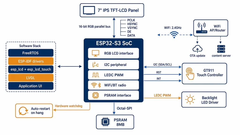
What makes it work is the convergence of three things happening at the same time. The ESP32-S3’s dual Xtensa LX7 cores running at 240 MHz can handle LVGL rendering workloads that would have required a dedicated GPU coprocessor three years ago. Octal-SPI PSRAM up to 8 MB gives the framebuffer space that fluid UI animation requires — two full frames at 800×480 in RGB565 need 1.5 MB minimum, comfortably inside the 8 MB envelope. And the RGB parallel LCD interface, combined with the esp_lcd component in ESP-IDF v5.x, removes most of the low-level timing work from the developer’s plate.
This guide is specifically organized around the 4.3-inch, 5-inch, and 7-inch panel sizes that dominate kiosk and industrial HMI deployments in the sub-$100 display market. Each size brings specific resolution trade-offs, touch controller calibration considerations, and mechanical integration factors. The development workflow, code patterns, and selection criteria in this guide apply across all three, with differences called out where they matter.
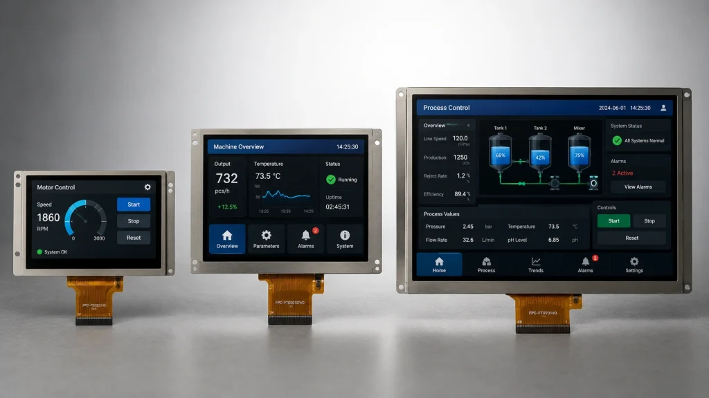
Panel Selection — Choosing the Right Size for Your Application
The 4.3″, 5″, and 7″ display sizes are not interchangeable. Each maps to different operator interaction patterns, enclosure constraints, and processing load profiles. Getting this decision right at the design stage avoids expensive hardware revisions later.
The 5-inch 800×480 IPS configuration is where most new kiosk and embedded HMI projects land. It offers enough pixel density that LVGL’s default font rendering (Montserrat 14, 20pt) looks sharp and professional at arm’s reach — roughly 40–60 cm for a kiosk interaction — while keeping the framebuffer size within a single 1 MB allocation from PSRAM. The 7-inch size is the first choice when the UI must display multiple zones simultaneously: a status panel, a process graph, and a button grid, for example, that would require scrolling or tab navigation on a 5-inch screen.
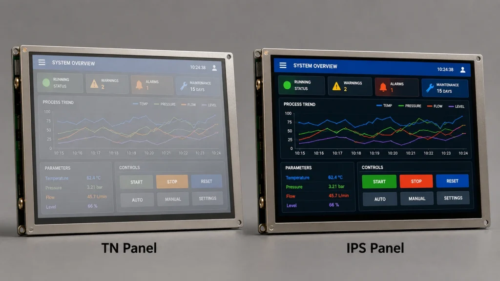
IPS vs. TN Panel Technology for HMI and Kiosk Use
For public-facing kiosk deployments and industrial HMI panels where operators approach from variable angles, IPS (In-Plane Switching) panel technology is not optional — it’s a minimum requirement. A TN panel’s color accuracy drops below 60% at viewing angles beyond ±30° from center, which means a kiosk mounted at chest height reads color-inverted to anyone who isn’t standing directly in front. IPS panels maintain ≥85% color accuracy at ±80° horizontal and vertical, which is the practical viewing angle range for kiosk-style use.
The trade-off is cost: IPS panels at 5–7 inch sizes typically carry a 15–25% BOM premium over equivalent TN panels. For industrial panel-mount applications where a single operator sits at a fixed position, TN panels can be a viable cost reduction. For anything kiosk-facing or in common-access locations, that premium is a necessary investment in product experience quality.
Touch Film Specification — What GT911 Needs from the Panel
The GT911 controller is calibrated at the factory to match the capacitive touch film dimensions of the specific panel it’s bonded to. This means you can’t swap touch controllers between panels of different sizes without rewriting the GT911’s configuration register block — the active area dimensions at registers 0x8068–0x806B must match the actual panel touch area in pixels.
When sourcing display modules for a new design, always verify that the supplied GT911 configuration block matches your panel’s active area. Request the baseline configuration file (a 186-byte binary or hex array) from the panel supplier as part of the procurement process. Modules sold without this documentation require manual sensitivity characterization — an engineering step that adds 2–5 days to bringup and produces inconsistent results across production batches.
Hardware Bring-Up — From Unpacking to First Pixel
The ESP32-S3 RGB Interface Pin Assignment
The ESP32-S3’s RGB LCD interface is matrix-assignable — any GPIO can serve any data or control signal function within the hardware constraints of the LCD peripheral. In practice, this flexibility creates a trap: choosing GPIO assignments without considering alternate functions, boot strapping pins, and USB/JTAG co-use leads to bring-up failures that look like timing errors but are actually pin-conflict issues.
The following assignment is validated for ESP32-S3 modules with PSRAM and avoids known conflict pins (GPIO19/20 used by USB-OTG, GPIO0 used for boot mode, GPIO45/46 with bus-keeper behavior):
The GPIO allocation below is for illustrative purposes only. The RGB interface signals of the ESP32-S3 have fixed GPIO constraints. Please refer to the ‘LCD Interface’ section of the ESP32-S3 Technical Reference Manual to confirm that the GPIO you select supports the corresponding signal function.
📌 FPC Connector Orientation
The most common first-hour bring-up failure is a reversed or misaligned FPC cable. Most 4.3–7″ display modules use a 40-pin or 50-pin ZIF connector with pin 1 clearly marked by a triangle or number on both the cable and connector body. Before powering on, verify pin 1 alignment at both ends. A reversed FPC connection typically doesn’t destroy hardware immediately, but it will produce no output and occasionally latches up the LCD peripheral, requiring a full power cycle to clear.
Timing Parameter Extraction from Panel Datasheets
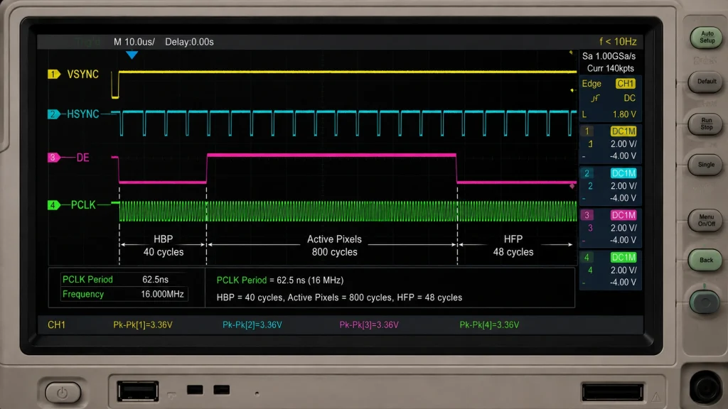
The RGB timing parameters (HBP, HFP, HPW, VBP, VFP, VPW, PCLK frequency) must match what the panel’s internal timing controller expects. These values are panel-specific — they’re not governed by a universal standard. The consequence of wrong values ranges from a blank screen (PCLK too high, or HBP too short) to a shifted or corrupted image (wrong blanking intervals).
Rather than listing generic values that may not match your panel, here’s the verification method: start with the panel datasheet’s ‘typical’ row in the timing table. If the datasheet provides only min/typ/max columns, always use the typical values first. Then iterate:
-
PCLK too high → blank screen or severe pixel noise. Halve the PCLK value and retry. Most 4.3″ panels are comfortable at 9 -12 MHz; 5″ / 7″ at 25–40 MHz depending on resolution.
-
Image shifted horizontally → HBP or HFP is wrong. Increase HBP by 10 clock cycles and retry. Repeat until image centers.
-
Partial image at top or bottom → VBP or VFP is wrong. Adjust by 2–4 line increments.
-
Diagonal color bands → polarity of PCLK edge is wrong. Toggle
flags.pclk_active_negin the panel config.
The full esp_lcd_rgb_panel_config_t structure with working example values for a common 7-inch 800×480 IPS panel:
GT911 Initialization for 4.3″, 5″, and 7″ Panels
The GT911 initialization sequence is the same regardless of panel size, but three parameters must be set correctly for each panel and are different between sizes: the active touch area width and height (registers 0x8068–0x806B), the touch sensitivity threshold (register 0x8057), and whether X/Y axes need swapping or mirroring based on the physical orientation of the touch film relative to the display driver IC scan direction.
Size-Specific GT911 Configuration Adjustments
Sensitivity adjustments must be based on actual testing. The capacitance characteristics of 7-inch panels differ from those of 4.3-inch panels due to the larger electrode spacing. Please prioritize using the configuration block provided by the supplier. If the touch is too sensitive (frequent accidental touches), try increasing the value of register 0x8057 by 0x08 (decreasing sensitivity); if the touch is insensitive (requiring firm pressure), decrease it by 0x08 (increasing sensitivity). Testing on a production prototype is essential, as environmental noise and cover material can affect optimal values.
The Reset Sequence — Executed Once, Gets Everything
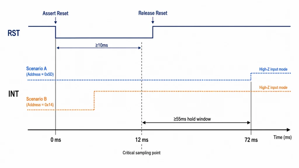
Rather than repeating the full GT911 initialization code from earlier guides in this series, here’s the critical production insight about the reset sequence that most getting-started tutorials omit: the INT pin level at the moment RST transitions LOW-to-HIGH determines the I²C address for the entire power cycle. If anything in your hardware causes the INT pin to float during that 55 ms window — a weak pull-down that charges up slowly, another device on the I²C bus that briefly drives INT high, or a GPIO interrupt misfiring — the GT911 may initialize on the wrong address, causing all subsequent I²C communication attempts to return NACK errors.
The hardware fix is a 10 kΩ pull-down resistor on the INT line to hold it firmly at the target level during the reset window. The firmware fix is a GPIO output drive during the reset sequence, then switched to input for interrupt operation — which is exactly what esp_lcd_touch_new_i2c_gt911() does when you set int_gpio_num correctly in the config struct.
LVGL Integration — Practical Configuration for Kiosk and HMI Use
Memory Architecture for Different Panel Sizes
The frame buffer memory architecture has a direct impact on UI smoothness. The calculation is straightforward: bytes per frame = H_res × V_res × 2 (for RGB565). For double-buffering (required for tear-free 60 fps with the ESP32-S3 RGB DMA engine), multiply by two:
All three configurations fit comfortably within the ESP32-S3’s 8 MB octal-PSRAM envelope with room for application data, WiFi stack buffers, and LVGL’s heap. The key sdkconfig entries that make this work — CONFIG_SPIRAM_MODE_OCT=y, CONFIG_SPIRAM_SPEED_80M=yund CONFIG_LCD_RGB_ISR_IRAM_SAFE=y — are the same regardless of panel size.
Furthermore, to improve the efficiency of CPU instruction fetching and data reading from PSRAM, `CONFIG_SPIRAM_FETCH_INSTRUCTIONS=y` and `CONFIG_SPIRAM_RODATA=y` must be enabled (in ESP-IDF v5.1+, this can be achieved through combinations such as `CONFIG_SPIRAM_USE_CAPS_ALLOC`). Simultaneously, the memory allocator used by LVGL should preferentially use PSRAM (by setting `LV_MEM_CUSTOM` or using `heap_caps_malloc(MALLOC_CAP_SPIRAM)`).
LVGL Widget Configuration for Kiosk vs. Industrial HMI
Kiosk applications and industrial HMI screens have different LVGL configuration requirements that stem from different usage patterns:
Backlight Control via LEDC PWM
Kiosk deployments need adaptive backlight brightness — a kiosk in a bright retail space needs 600+ nits, the same unit in a dimly lit corridor needs 200 nits or it becomes an eyesore. Industrial HMI panels need backlight dimming during process idle states to extend backlight life. Both use the ESP32-S3 LEDC peripheral:
💡 Backlight PWM Frequency and Flicker
Backlight PWM below 1,000 Hz can produce visible flicker in peripheral vision during rapid head movement — a particularly noticeable issue in kiosk applications where users often approach from the side. The 5 kHz frequency in the example above is above the perceptible range for peripheral flicker (typically 200–500 Hz depending on individual sensitivity) and well within the LEDC peripheral’s comfortable operating range. For medical device displays where flicker is regulated under IEC 62341-6-4, verify compliance with your specific backlight driver IC’s PWM behavior.
Building for Reliability — What Kiosk and HMI Deployments Demand
A working demo on a dev board is table stakes. A product that runs reliably for 18 months in a public kiosk, unmaintained except for software updates, is an engineering achievement. The following areas separate demo-quality firmware from production-quality deployments.
Watchdog Coverage for Unattended Operation
Kiosk deployments are unattended by definition. A freeze that requires a power cycle will stay frozen until the next maintenance visit. The minimum watchdog coverage for any ESP32-S3 kiosk or HMI product:
-
Hardware watchdog (RWDT): set to 30 seconds. This catches complete firmware hangs including FreeRTOS scheduler failure. Requires all tasks to kick it, or use task watchdog (TWDT) per task.
-
Task watchdog (TWDT): 10-second timeout per FreeRTOS task. The LVGL rendering task, the touch read task, and the network task each need independent kick calls.
-
Application-level display flush watchdog: a software counter that triggers
esp_restart()if the LVGL flush callback hasn’t been called in 60 seconds. This catches LVGL deadlocks that don’t trigger the TWDT.
Network Resilience for Connected Kiosks
WiFi-connected kiosks — for content updates, transaction processing, or remote monitoring — need explicit handling for every network failure mode. The naive pattern of calling a network API and expecting it to succeed causes firmware hangs or corrupted UI state when networks are unavailable.
The production pattern: all network operations run in a dedicated FreeRTOS task with a timeout. Results are posted to a FreeRTOS queue. The LVGL UI task reads from the queue and updates the display. If the queue remains empty for a configured timeout, the UI switches to an ‘offline mode’ state that serves cached content. This architecture ensures the UI remains responsive and the LVGL task never blocks waiting for a network response.
Preventing GT911 Calibration Drift in Field Units
One failure mode that appears in kiosk deployments 3–6 months after launch: touch coordinates slowly drift from their correct positions, requiring increasing pressure for accurate tap recognition. This is almost always caused by one of two things: accumulation of conductive contamination on the cover glass surface (perspiration salts, cleaning chemicals) that shifts the baseline capacitance reading, or GT911 sensitivity register drift if the configuration block wasn’t protected with the correct checksum.
The firmware mitigation: validate the GT911 configuration checksum on every boot (register 0x80FF must match the two’s-complement sum of registers 0x8047–0x80FE). If the checksum is invalid, immediately rewrite the golden configuration and reset the controller. Add a ‘touch recalibrate’ function accessible via a hidden maintenance menu (for example, holding the top-left corner for 10 seconds) that triggers a GT911 configuration re-sync without requiring firmware reflash.
Product Selection — Matching Display to Application
The technical criteria for evaluating 4.3–7″ display modules for ESP32-S3 kiosk and HMI products reduce to a checklist that can be applied during the sourcing process. Working from this checklist prevents the most common hardware selection mistakes that emerge during production bring-up.
Kadi Anzeige’ S industrial TFT touch display module range covers 4.3″, 5″, and 7″ sizes with IPS panel technology, factory-calibrated GT911 capacitive touch, and full RGB timing documentation — the three criteria that most frequently cause sourcing problems when working with less-documented panel suppliers. Their custom cover glass guide is worth reviewing early in the enclosure design process if your kiosk product requires branded glass, non-rectangular cutouts, or specific surface finishes. And for teams still deciding between panel technologies, their TN vs IPS vs VA comparative analysis provides the viewing-angle and contrast data for each technology class applied to industrial use cases.
Development Workflow Summary — From Sourcing to Shipping
The complete development sequence for an ESP32-S3 RGB kiosk or HMI display product, with the steps that most commonly introduce delay when skipped:
Produktreferenz & Technischer Support
For 4.3″, 5″, and 7″ industrial TFT-LCD touch display modules with factory-calibrated GT911, IPS panel technology, and full RGB timing documentation for ESP32-S3 integration, contact Kadi Display at Sales@sz-kadi.com. OEM and ODM services available, including custom cover glass, optical bonding, and wide-temperature specifications for kiosk and industrial HMI deployments. Browse industrial TFT touch display modules →
Haftungsausschluss: Code examples, GPIO assignments, and timing values in this guide are illustrative references and must be verified against your specific hardware before use. FPC pinouts, timing parameters, and GT911 register defaults vary between panel suppliers and module revisions. Always obtain and follow the datasheet for your specific panel. ESP-IDF API signatures may change between SDK versions; refer to Espressif’s official documentation for your target version. GT911 is a trademark of Shenzhen Goodix Technology Co., Ltd. ESP32-S3 is a trademark of Espressif Systems. LVGL is open-source software under MIT license. All other trademarks belong to their respective owners.
Vorherige
Common ZIF Connector Problems in Industrial Touchscreens and How to Fix Them
Nächster
How to Bring Up a Custom MIPI DSI Touch Display on Raspberry Pi CM4: Panel Driver, Device Tree Overlay, and GT928 Touch
Hinterlasse einen Kommentar

Neueste Blog & Nachrichten
- MIPI DSI Display Works at Room Temperature but Fails After Warm-Up: A Troubleshooting Workflow
- How to Choose an LCD Controller Board: Architecture, EDID, Timing and Latency
- Industrial Display RFQ Checklist: Build a Supplier-Ready Evidence Package
- Industrial LCD Drop-In Replacement Checklist: From Hard Stops to Release Evidence
- MIPI DSI in Industrial LCD Displays: What Engineers Should Know

