




Startseite
-
Blog & Neuigkeiten
-
MIPI DSI Works at Low Refresh Rates but Fails at 60 Hz: A Practical Troubleshooting Workflow
MIPI DSI Works at Low Refresh Rates but Fails at 60 Hz: A Practical Troubleshooting Workflow
2026-09-10
16:06
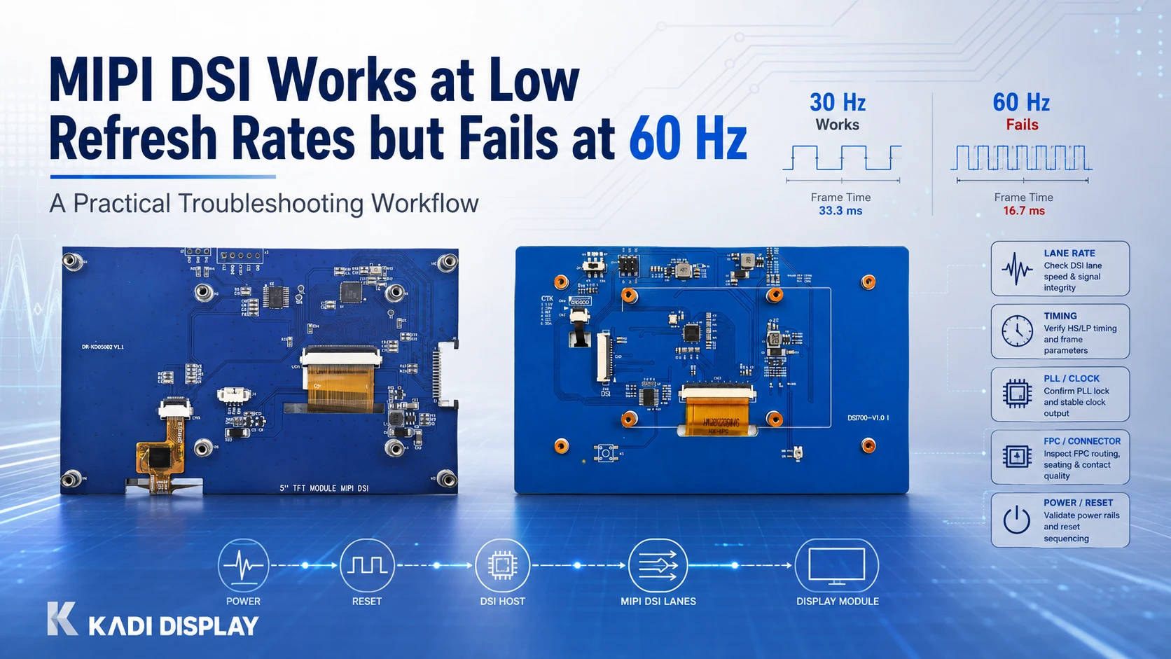
When a MIPI DSI display works at a low refresh rate but fails at 60 Hz, the problem is often exposed by the higher lane rate rather than caused by one single component. Check the complete timing budget, host PLL settings, panel lane-rate range, DSI mode, FPC and connector path, power sequencing, and software configuration before deciding to replace hardware. A matching connector alone does not establish MIPI DSI compatibility.
What Does “Works at Low Refresh Rates but Fails at 60 Hz” Tell You?
This symptom is a useful starting point because increasing refresh rate raises the pixel clock and the amount of data the DSI link must transport per second. A display may remain stable at 30 Hz, for example, then show a black screen, flicker, image corruption, intermittent frame errors, or boot failures at 60 Hz.
That does not automatically prove a signal-integrity problem. The failure can begin in one of several places:
-
The required lane rate exceeds a supported host or panel operating range.
-
The host driver selects a PLL value that differs from the calculated value.
-
The chosen video mode, pixel format, or timing table is not accepted by the panel.
-
The D-PHY channel loses enough margin at the higher data rate to become unstable.
-
Reset, power, initialization, or Device Tree settings are valid at one configuration but not another.
Start by documenting the exact failure condition. Record the active resolution, target refresh rate, pixel format, lane count, DSI video or command mode, requested clock settings, host platform, and the behavior seen on screen. This prevents unrelated changes from being treated as a fix.
Run a Quick Lane-Rate and Timing Check First
The first engineering question is whether the 60 Hz configuration is theoretically viable for both ends of the link.
Use the panel timing table rather than active resolution alone. Horizontal and vertical totals include active pixels plus sync and porch intervals. For initial video-mode planning:
Per-lane planning rate = Htotal x Vtotal x refresh rate x transported bits per pixel / active data lanes
For RGB888, transported data is normally 24 bits per pixel. RGB565 uses 16 bits per pixel. RGB666 handling depends on whether the host uses packed or loosely packed transmission, so the actual transport format must be confirmed in the controller documentation.
The calculation is a planning step, not final approval. DSI packet scheduling, blanking treatment, host clock rules, and implementation overhead can change the required operating point. The host must also generate an achievable setting within the panel receiver range.
Compare these items before changing the display module:
-
Panel Htotal, Vtotal, refresh-rate limits, lane count, and supported HS lane-rate range
-
Host DSI controller limits, including minimum and maximum operating rates where specified
-
PLL steps, requested rate, achieved rate, byte clock, and clock tolerance
-
Pixel format and DSI mode supported by both endpoints
-
Physical lanes actually routed from the host to the module
More data lanes can lower the required rate per lane for the same payload, but only when the host, panel, pinout, firmware, and board routing all support that lane count. It does not automatically make a panel operate at 60 Hz.
For a deeper timing calculation, link readers to MIPI DSI bandwidth calculations rather than duplicating the full design guide in this troubleshooting article.
Use a Fault Tree Before Replacing Parts
A structured test sequence is more efficient than changing the panel, cable, and software at the same time.
| Observation | Most likely area to check first | Next action |
|---|---|---|
| Lower refresh rate is stable; 60 Hz fails consistently | Lane-rate budget, timing, PLL, DSI mode | Recalculate using complete timing and compare actual programmed rate |
| A different lane count changes the symptom | Lane support, pinout, board routing | Confirm endpoint support and all routed differential pairs |
| Failure changes with another FPC, adapter, or cable position | Signal path and connector mechanics | Check FPC orientation, pinout, bend radius, connector seating, and PCB routing |
| Screen is black immediately after boot | Power, reset, panel initialization, driver | Review startup sequence, Device Tree, mode table, and panel driver |
| Image is stable but touch is not | Touch subsystem | Check I2C address, interrupt/reset wiring, power, and driver setup |
| Failure appears only after heat, voltage change, or long operation | System validation margin | Repeat tests across relevant operating conditions and record DSI errors |
This fault tree separates physical connection, interface signaling, driver support, and whole-system validation. A module may fit the same connector but use a different pinout, lane arrangement, timing set, initialization sequence, or touch configuration.
Test the Link Without Assuming the Root Cause
Make one controlled change at a time. If the panel supports intermediate operating points, test lower and higher refresh rates while holding resolution, lane count, pixel format, and DSI mode constant. Then compare the behavior with a documented 60 Hz configuration.
Useful evidence includes:
-
Requested and achieved lane rate
-
Pixel clock and byte-clock values, with units clearly labeled
-
DSI mode and active data-lane count
-
Host DSI error status or error counters, if available on the platform
-
Panel initialization sequence and reset timing
-
Whether the problem follows a specific FPC, connector, adapter board, or PCB revision
-
Whether image errors change with test patterns, temperature, supply condition, or mechanical movement
At higher lane rates, the electrical channel becomes less tolerant of loss, reflections, crosstalk, jitter, poor reference-plane continuity, and connector variation. The relevant path is the complete channel: host PCB, any adapter board, FPC, connector interfaces, and the display module input.
Do not describe a stable bench image as production qualification. Final verification should use the intended PCB, cable/FPC path, connector arrangement, power conditions, enclosure constraints, and firmware configuration.
Common Root Causes Behind a 60 Hz-Only Failure
Lane Rate, Pixel Timing, and Packet Budget
A calculation can look valid while the programmed link still fails. Common causes include using active resolution instead of complete timing totals, selecting an unsupported pixel format, omitting the host’s packet method, or assuming a continuous PLL frequency when the controller offers only discrete steps.
Video mode needs particular attention. Burst and non-burst modes can handle blanking and packet scheduling differently. A panel and host may both support MIPI DSI but not support the same mode or timing implementation. Confirm the selected mode in both the panel specification and host platform documentation.
Driver, Device Tree, and Initialization Settings
If the display worked before a BSP or Linux update, compare the active Device Tree, panel driver, mode timings, lane count, pixel format, reset GPIO behavior, regulator configuration, and initialization sequence. A driver may also report a clock value differently from the value used in the D-PHY register, so identify whether a setting represents pixel clock, byte clock, PLL reference, or HS lane bit rate.
The same principle applies to Raspberry Pi and embedded platforms. A Raspberry Pi DSI connector provides a physical connection path, but OS version, board model, cable, display settings, touch setup, and orientation still affect the result. Kadi’s Raspberry Pi MIPI DSI display category states that compatibility should be reviewed by model and OS combination.
FPC, Connector, PCB, and Power Integrity
An FPC that carries a lower-rate configuration can become the limiting element at 60 Hz. Inspect connector seating, pin numbering, FPC direction, cable length, repeated bends, strain from the enclosure, and any intermediate adapter board. Confirm that the board design preserves differential-pair impedance and return paths through connectors, vias, and layer transitions.
Power and reset should also remain in the investigation. A marginal reset interval, regulator sequence, or backlight-related disturbance can appear as a link failure even when the DSI lane-rate calculation is correct.

Choose the Right Fix: Parameter, Module, FPC, PCBA, or Structure
The appropriate action depends on the evidence, not simply on the desired refresh rate.
If the panel and channel specifications support 60 Hz but timing, PLL rounding, lane selection, or DSI mode is wrong, correct the configuration first. If the selected panel does not support the necessary timing, lane count, or receiver operating range, a module with matching documented specifications may be required.
If the issue changes when the FPC, connector, or mechanical position changes, focus on the physical channel. That may mean revising the FPC route, connector selection, adapter board, or PCB layout rather than changing the LCD.
A project that also needs a different touch interface, cover lens, connector arrangement, backlight configuration, controller board, or mounting method may exceed a standard module selection. In that situation, a custom display assembly can be evaluated around the display, touch, cover glass, bonding, FPC, connector, PCBA, and mechanical requirements as applicable.
For a known Raspberry Pi-based configuration, the 7.0-inch 1024 x 600 MIPI DSI touch display is a relevant reference product because it uses MIPI DSI for video and I2C for touch. Its product page also notes that compatibility and setup depend on the Raspberry Pi model, operating system, DSI cable, settings, touch configuration, and orientation. Confirm the delivered configuration against the product specification rather than applying its information to unrelated modules.
When to Move from a Module to a Solution-Level Review
A bare TFT panel may be appropriate when an OEM already controls the touch, electronics, mechanical design, and validation path. A Touch Display Module can be more suitable when the LCD, touch panel, and interface arrangement need to be evaluated together.
When the issue includes display selection plus cover glass, bonding, FPC exit direction, connectors, mounting hardware, or a controller board, the decision moves toward a Custom Display Assembly. When these elements must work together as a defined user-interface subsystem, a Modular HMI Solution may reduce integration ambiguity.
Kadi Anzeige can be approached at the product or project level depending on the scope. Any final compatibility determination should remain conditional on the selected host platform, panel specification, software configuration, and sample or system validation.
Schlussfolgerung
A MIPI DSI display that is stable at a low refresh rate but fails at 60 Hz should be treated as a system-level diagnostic problem. Verify the exact timing and lane-rate budget first, then separate host configuration and driver issues from D-PHY channel, FPC, connector, power, and mechanical-integration risks.
For a technical review or display-selection discussion, Kontakt Kadi Display with the host platform, panel model or datasheet, resolution, timing, lane count, DSI mode, pixel format, FPC/connector details, and a concise description of the 60 Hz symptom. Include relevant drawings or failure photos when the issue may involve cable routing or mechanical stress.
Häufig gestellte Fragen
Can a MIPI DSI display work at 30 Hz but fail at 60 Hz because of signal integrity?
Yes. A higher refresh rate usually requires a higher pixel clock and lane rate, which can reduce electrical margin. However, timing, PLL configuration, panel lane-rate limits, DSI mode, and driver settings should be checked before attributing the issue solely to signal integrity.
Does adding more MIPI DSI lanes fix a 60 Hz failure?
It can reduce the data rate required on each lane, but only if the host, panel, firmware, pinout, and PCB routing support the added lanes. It does not correct an incompatible timing table, unsupported DSI mode, or poor connector/FPC path by itself.
Does the same MIPI DSI connector mean two displays are compatible?
No. Physical connection is only one condition. Compare pinout, lane count, lane order, power rails, reset signals, DSI mode, timing, pixel format, panel initialization, touch interface, driver support, and complete system behavior.
Should I increase the lane rate above the calculated minimum?
Only when the resulting value remains within the supported ranges of the host and panel and the physical channel is suitable for that operating point. A higher lane rate can create payload margin while reducing electrical margin, so it should be verified against the actual implementation.
What should be included in an RFQ for a replacement or custom MIPI DSI display?
Provide the host platform, resolution, target refresh rate, panel timing, pixel format, lane count, DSI mode, touch requirements, FPC pinout, connector details, brightness target, operating conditions, mechanical drawing, application, and observed failure condition. This gives the supplier enough information to distinguish a standard-module request from a modified module or project-specific display assembly.
Vorherige
PCAP Touch Works on the Bench but Fails After Metal Enclosure Assembly: An Isolation Checklist
Nächster
MIPI DSI Works After Power-On but Goes Black After Warm Reboot: Reset and Reinitialization Checks
Hinterlasse einen Kommentar

Neueste Blog & Nachrichten
- Industrial LCD EOL: What Happens from Pre-Announcement to Replacement Mass Production?
- Electronic Component Obsolescence Management for Industrial Displays: An OEM Guide
- How to Develop a Production Ready Custom Display Assembly TFT Module Touch Cover Glass FPC Bonding and Mounting
- 15 Pin vs 22 Pin Raspberry Pi DSI Connectors Cable Pinout and Compatibility
- Native MIPI DSI vs LVDS or HDMI Bridge: An OEM Display Architecture Decision Guide

