




How to Choose FFC/FPC Connectors for Industrial Touchscreen Products
2026-07-10
10:14
How to Choose FFC/FPC Connectors for Industrial Touchscreen Products
A practical selection framework covering pin count, pitch, mated height, locking mechanism, temperature rating, and mating cycle life — the six parameters that determine whether a connector survives years of industrial touchscreen operation
Por el equipo técnico de Kadi Display | www.kadidisplay.com
Why Connector Selection Deserves the Same Rigor as Display Selection
Engineers spend weeks comparing panel brightness, touch technology, and interface protocol when specifying an industrial touchscreen. The connector that physically joins the display module’s FPC tail to the host PCB often gets selected in minutes — frequently by simply matching whatever connector the reference design used, without reviewing whether that connector’s pin count, pitch, mated height, locking style, temperature rating, or mating cycle rating actually fits the product’s service requirements.
This is a costly oversight because the connector sits at a uniquely vulnerable point in the system. It’s the only component in the signal path between the touch controller and the host processor that’s subject to mechanical handling during assembly, mechanical stress during enclosure integration, and ongoing thermal and vibration stress throughout the product’s service life. A connector that’s marginally undersized for the application doesn’t usually fail during the first functional test — it fails six months later, in the field, in a way that looks exactly like a software or driver problem.
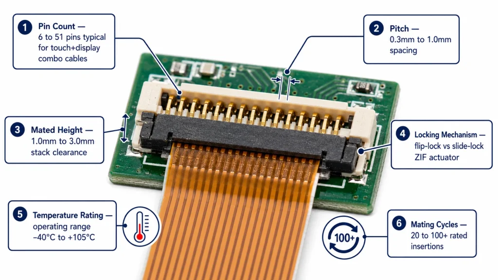
This guide works through the six parameters that actually distinguish a correct connector choice from a marginal one for industrial touchscreen products: pin count, pitch, mated height, locking mechanism, operating temperature range, and mating cycle durability. Each section includes the engineering rationale, representative data, and a specific checklist item to confirm with any connector or display module supplier.
Pin Count: Matching the Signal Budget
Cuenta de Pines
Why it matters: Pin count is determined by what signals the FPC must carry — not just touch data, but potentially backlight power, display data, and ground returns sharing the same cable. Under-provisioning pin count forces a redesign late in the project; over-provisioning wastes board space and increases connector cost without benefit.
Engineering data: A capacitive touch-only FPC (GT911 or similar) typically requires 6 pins: SDA, SCL, INT, RST, VDD, GND. A combined touch + RGB display FPC can range from 30 to 51 pins depending on color depth and whether backlight power shares the cable. MIPI DSI cables for Raspberry Pi-class hosts are standardized at 15 pins (Pi 4B, Pi 5, full-size boards) or 22 pins (Pi Zero, CM4 carrier designs) — these two standards are electrically similar but mechanically incompatible without an adapter board.
Selection checklist: Count every signal that must cross the connector: data lines, clock lines, power rails, ground returns, and any spare/reserved pins the panel vendor recommends for future revisions. Add 10–15% pin margin for unexpected future signal requirements if board space allows. Confirm with the display supplier whether their cable combines touch and display signals on one connector or uses separate connectors — this changes the pin count math significantly.
The pin mismatch between Raspberry Pi generations is a documented practical headache: full-size Raspberry Pi boards from Model B+ through Pi 5 use a 15-pin DSI connector, while the Pi Zero and Zero 2 W use a narrower 22-pin connector that is electrically similar but physically different — a detail that catches out engineers ordering replacement cables across a mixed Pi fleet. Kadi Display’s guide on MIPI DSI support across STM32, Raspberry Pi, and ESP32 platforms documents this distinction along with the broader pin-count planning considerations for embedded display projects.
Pitch: The Tolerance Budget That Determines Assembly Yield
Connector Pitch
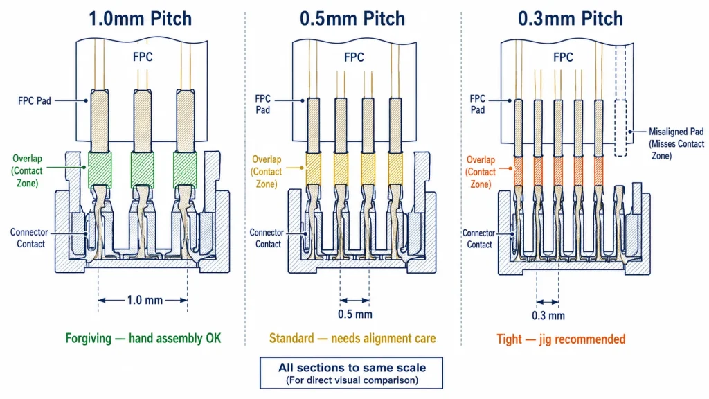
Why it matters: Pitch — the center-to-center spacing between adjacent contacts — directly determines how much insertion misalignment the connector tolerates before a conductor falls outside its contact zone. This is the single parameter most responsible for production yield issues when a connector is selected without considering manual assembly tolerance.
Engineering data: Standard pitches for industrial touch and display FPC connectors are 1.0 mm, 0.5 mm, and 0.3 mm. At 1.0 mm pitch, the contact pad is typically 0.5 mm wide with roughly 0.35 mm of contact overlap — tolerant of ±0.5 mm insertion variance, well within hand-assembly capability. At 0.5 mm pitch, the contact pad narrows to roughly 0.25 mm with about 0.2 mm overlap, requiring ±0.15 mm insertion accuracy. At 0.3 mm pitch, the margin shrinks further to roughly ±0.08 mm — a tolerance that benefits significantly from a mechanical insertion jig rather than manual placement.
Selection checklist: Match pitch to assembly method: 1.0 mm pitch for manual or low-volume assembly where jigs aren’t practical; 0.5 mm pitch for standard production with basic visual alignment aids; 0.3 mm pitch only when board space genuinely requires it, paired with a production fixture. Confirm the pitch matches exactly between the display module’s FPC and the host connector — mismatched pitch is not adapter-fixable.
Mated Height: The Enclosure Clearance Constraint
Mated Height
Why it matters: Mated height — the total stack height of the connector and cable once fully seated — determines how much vertical clearance the enclosure design must allocate at the connector location. This becomes a binding constraint in thin industrial panel-mount displays, handheld terminals, and any enclosure where front-to-back depth is limited by the application.
Engineering data: Low-profile FPC connectors range from 1.0 mm to 1.5 mm mated height — common in slim industrial touchscreens and panel-mount HMI bezels under 20 mm total depth. Standard-profile connectors run 2.0 mm to 3.0 mm, offering greater contact normal force and mechanical robustness at the cost of additional clearance requirement. The mated height must be measured from the PCB surface to the highest point of the connector body with the FPC cable inserted and locked — not the unmated connector height alone, which underestimates the true clearance need by 0.3–0.8 mm depending on cable thickness.
Selection checklist: Request the supplier’s mated height dimension specifically — many datasheets list only the unmated connector height. Verify clearance against the enclosure’s internal depth at the connector mounting location, including any standoffs, gaskets, or EMI shielding that adds to the stack. For panel-mount displays under 15 mm bezel depth, confirm low-profile connector availability before finalizing the mechanical design.
Locking Mechanism: Flip-Lock vs Slide-Lock vs Push-Pull
Locking Mechanism
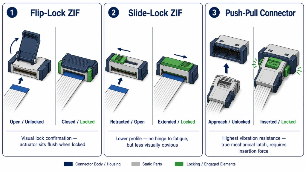
Why it matters: The locking mechanism determines both how reliably the connector maintains contact under vibration and how forgiving the connector is of repeated insertion during development and field service. Choosing the wrong locking style for the application is a common source of both production assembly errors and field reliability complaints.
Engineering data: Flip-lock (top-actuated) ZIF connectors use a hinged actuator that flips up for insertion and down to lock — intuitive for manual assembly, easy to visually verify locked state, but the actuator itself is a fragile feature that can crack if forced. Slide-lock (side-actuated) connectors use a sliding latch — generally lower profile and more vibration-resistant since there’s no hinged part to loosen, but less visually obvious whether fully locked. Push-pull (non-ZIF) connectors use a friction-fit or latching plug design without zero-insertion-force operation — these provide the highest vibration resistance and an unambiguous tactile click, at the cost of requiring real insertion force that increases FPC stress over repeated cycles.
Selection checklist: Match locking style to handling pattern: flip-lock for designs with infrequent disassembly and a priority on visual verification (production-line friendly); slide-lock for thin-profile, vibration-sensitive applications; push-pull only where mating cycles are genuinely low and maximum vibration resistance matters more than insertion ease. For any locking style, specify and verify the actuator’s rated actuation cycle count separately from the FPC’s own insertion cycle rating.
Rango de temperatura de funcionamiento
Temperature Rating
Why it matters: Connector housing material and contact spring properties both have temperature limits that, if exceeded, cause permanent deformation, contact force relaxation, or housing cracking — failure modes that are invisible at room temperature qualification but appear after months of thermal cycling in the field.
Engineering data: Standard consumer-grade FPC connectors are typically rated 0°C to +70°C, sufficient for indoor office-environment equipment. Industrial-grade connectors extend this to −30°C to +85°C or wider, using engineering-grade housing plastics (typically high-temperature nylon or LCP — liquid crystal polymer) and beryllium-copper or phosphor-bronze contact springs rated for sustained elevated temperature without permanent set. The contact spring’s normal force — the clamping force holding the FPC against the contact — typically degrades by 15–30% after sustained exposure near the connector’s rated maximum temperature, which is why a connector rated exactly at the application’s expected temperature, with no margin, is a marginal specification rather than a safe one.
Selection checklist: Specify connector operating temperature with at least 10–15°C margin above the application’s expected maximum sustained temperature — not the absolute peak, but the sustained operating condition, since spring force relaxation is a function of cumulative thermal exposure. Request the connector datasheet’s contact force retention curve versus temperature and cycling, not just the pass/fail operating range. For displays paired with wide-temperature panels (−30°C to +85°C, as commonly specified for outdoor or vehicle-mount applications) ensure the connector rating matches or exceeds the panel’s own rating — a wide-temperature display paired with a standard-temperature connector creates a hidden bottleneck.
Mating Cycle Durability
Mating Cycle Rating
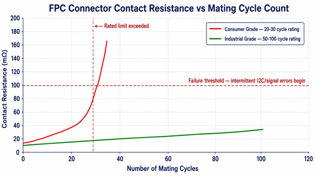
Why it matters: Mating cycle rating specifies how many insertion-removal cycles the connector can withstand while maintaining contact resistance within specification. This number matters more than most engineers initially assume, because development bring-up, production rework, and field service all consume mating cycles — and a connector exhausted of its rated cycles exhibits exactly the symptom of an unrelated I²C or signal integrity fault: intermittent contact, rising resistance, and eventual open circuit.
Engineering data: Standard consumer ZIF connectors are typically rated for 20–30 mating cycles. Industrial-grade connectors extend this to 50–100+ cycles through improved contact spring metallurgy and surface plating. Each cycle incrementally wears the contact spring’s elastic limit and can introduce microscopic wear debris that increases contact resistance — typically by 2–5 mΩ per 10 cycles in a well-designed connector, accelerating non-linearly as the rated cycle count is approached. A connector that has been inserted and removed 25 times during bring-up and engineering validation, then specified at a 20-cycle rating for production, has already exceeded its rated life before the first production unit ships.
Selection checklist: Track and budget mating cycles across the product lifecycle: development bring-up (typically 10–30 cycles), production test/rework (5–15 cycles), and field service access (varies by maintenance design, 0–10 cycles over product life). Sum these and specify a connector rated at least 1.5× the total expected cycle count. For products requiring field-serviceable displays, specify industrial-grade connectors with 50+ cycle ratings as standard, not an upgrade option.
The Six-Parameter Decision Matrix
Applying all six parameters together for three common industrial touchscreen deployment profiles:
Sourcing Display Modules with Correctly Specified Connectors
Connector specification is frequently the least documented attribute in a display module’s published datasheet — brightness, resolution, and touch technology are headline specs, while pin count, pitch, mated height, locking style, temperature rating, and mating cycle life are often buried or absent entirely. For B2B industrial projects, this information must be requested explicitly rather than assumed from a product photo.
Kadi Display’s guide on choosing an industrial TFT LCD display module emphasizes confirming signal type, connector position, and FPC direction before sample approval — exactly the kind of mechanical-fit verification that prevents late-stage project delays. Their comparison of custom industrial displays versus off-the-shelf modules further notes that a small mismatch in FPC direction or connector position can become expensive once enclosure tooling has already started — reinforcing why connector parameters belong in the earliest design review, not an afterthought during pilot production.
For touch-specific connector and FPC integration guidance, particularly around GT911-based capacitive touch modules where I²C signal integrity depends heavily on connector contact quality, Kadi Display’s technical article on connecting GT911 touch to LVGL on ESP32-S3 notes that touch I²C lines should be kept short, referenced to stable ground, and separated from noisy backlight and RGB switching paths — layout practices that depend directly on having selected a connector with adequate pin count and shielding characteristics from the outset.
Connector Specification Checklist — 12 Questions Before Order
Soporte técnico y referencia de productos
For industrial TFT-LCD and touch display modules with fully documented FPC connector specifications — pin count, pitch, mated height, locking style, temperature rating, and mating cycle data — contact Kadi Display at Sales@sz-kadi.com. OEM and ODM services available, including custom FPC direction, connector position, and cable length. Browse industrial display module options →
Descargo de responsabilidad: Connector specifications, contact resistance figures, and mating cycle data in this guide are representative industry ranges for educational reference and must be verified against the specific connector manufacturer’s datasheet for your design. Actual performance varies by manufacturer, plating, and application conditions. All brand and product names are the property of their respective owners. No affiliation with any connector manufacturer is implied. Compliance and qualification testing should be performed according to relevant industry standards for your target application.
PREVIOR
Designing Industrial LCD HMIs for 10-Year Operation Without Image Retention Problems
Siguiente
LCD Display Connector Failure Modes: ZIF Lock, FPC Cable, Solder Joint, and Contact Wear
Deja un comentario

Últimos blogs y noticias
- Industrial LCD EOL: What Happens from Pre-Announcement to Replacement Mass Production?
- Electronic Component Obsolescence Management for Industrial Displays: An OEM Guide
- How to Develop a Production Ready Custom Display Assembly TFT Module Touch Cover Glass FPC Bonding and Mounting
- 15 Pin vs 22 Pin Raspberry Pi DSI Connectors Cable Pinout and Compatibility
- Native MIPI DSI vs LVDS or HDMI Bridge: An OEM Display Architecture Decision Guide

