Inicio
-
Blog & Noticias
-
Native MIPI DSI vs LVDS or HDMI Bridge: An OEM Display Architecture Decision Guide
Native MIPI DSI vs LVDS or HDMI Bridge: An OEM Display Architecture Decision Guide
2026-10-08
00:00
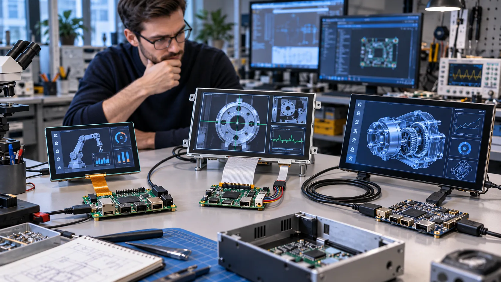
Native MIPI DSI is a sensible choice when the host processor, panel, driver and FPC are already aligned. A DSI-to-LVDS or DSI-to-HDMI bridge is more suitable when the host and panel use different interfaces, an existing controller-board architecture must be retained, or a standard video input simplifies system integration. Neither architecture is automatically suitable. OEM teams should verify physical connection, interface and signal behavior, software support, and complete-system operation before releasing a display design.
What Symptoms Point to an Architecture or Compatibility Problem?
The first symptom often appears before the architecture is fully understood:
-
A display works on a development board but remains black on a custom carrier board.
-
An HDMI monitor works, while a native MIPI DSI panel does not initialize.
-
An LVDS panel has backlight but no image.
-
The image is stable at a lower refresh rate but fails at the target rate.
-
Video works, but touch input does not.
-
The display fails or flickers only after the module is installed in its enclosure.
These symptoms do not necessarily mean that the panel is defective. They can indicate a mismatch between the host output, bridge configuration, panel timing, FPC, power sequence, driver, or mechanical installation. Classify the symptom before ordering a replacement module.
Quick Judgment—When Does Each Architecture Fit?
The following decision logic provides a starting point. Final compatibility still depends on the selected host, panel and software configuration.
| Arquitectura | Suitable starting condition | Key checks | Riesgo principal |
|---|---|---|---|
| MIPI DSI nativo | The host has a usable DSI display output and the panel is designed for that host class | Lane count, lane rate, PHY, timing, initialization, driver, FPC | Similar connectors can conceal different electrical and software requirements |
| DSI-to-LVDS bridge | The host provides DSI but the selected panel or installed base uses LVDS | LVDS channel, VESA/JEIDA mapping, pixel clock, bridge setup, power and reset | The bridge and panel must be configured as one signal path |
| DSI-to-HDMI bridge | The system benefits from a standard HDMI input or an existing HDMI controller board | Input/output direction, resolution, EDID or configuration, power, touch path, enclosure | HDMI input does not mean that a bare TFT panel accepts HDMI directly |
Choose Native MIPI DSI When the Host and Panel Are Directly Compatible
Native MIPI DSI can reduce conversion hardware in a compact embedded product when:
-
The exact SoC or carrier board provides a DSI Display Host, rather than only MIPI CSI.
-
The host and panel support compatible lane counts, data rates, PHY behavior, resolution, refresh rate and pixel format.
-
A panel driver, initialization sequence and Device Tree configuration are available for the operating system.
-
The FPC length, connector orientation and installation distance are practical for the enclosure.
The tradeoff is bring-up responsibility. A DSI label on both devices does not prove that initialization commands, timing values, reset behavior or software support will match.
Choose a DSI-to-LVDS Bridge When LVDS Is the Practical Panel-Side Interface
A DSI-to-LVDS bridge can be considered when the host processor has DSI output but the preferred industrial panel uses LVDS. This may fit a product that already has LVDS controller-board knowledge, panel availability or an established internal cable route.
Confirm single- or dual-channel operation, VESA or JEIDA mapping, connector pinout, pixel clock, timing, bridge configuration, power rails and reset sequence. Cable distance, electromagnetic environment and panel size can also influence the architecture. The bridge is not a universal compatibility layer; its input, output and configuration must match the complete system.
Choose a DSI-to-HDMI Architecture When Standardized Video Input Matters
A DSI-to-HDMI architecture may be useful when the product needs a standard HDMI input or when an existing HDMI controller board simplifies the host-side connection. This approach is closer to a display device with control electronics than to a bare panel.
Check whether the HDMI path is an external input, a bridge output or a controller-board interface. Confirm resolution, refresh rate, power, configuration method and the separate touch connection. USB or I²C may carry touch data while HDMI carries video. These paths should be specified independently.
Build a Fault Tree Before Replacing the Module
Host-Side Branch
Confirm the exact processor and board design:
-
Is the interface DSI Display Host or MIPI CSI?
-
Are the DSI pins routed to an accessible connector?
-
Are pin multiplexing, clock sources and lane settings enabled?
-
Does the selected BSP support the display controller?
A processor datasheet can show silicon capability, but the carrier-board schematic and software configuration determine whether the interface is usable in the product.
Bridge and Panel-Side Branch
Check the complete signal chain:
-
Is the bridge direction correct?
-
Do panel timing and pixel format match the output?
-
Are LVDS channel selection and mapping correct?
-
Are initialization, reset and backlight sequences configured?
-
Does the controller board require a defined configuration or EDID behavior?
Touch, FPC and Mechanical Branch
Treat touch as a separate branch. Check its I²C or USB path, address, power and driver independently from video. Then inspect FPC contact direction, pitch, pinout, lock position and bend path. A module that works on a bench can fail after a connector is loaded by the enclosure or the FPC is bent around a sharp route.
Test Method—Verify Four Compatibility Layers in Order
Physical Connection
Record the connector type, pitch, pinout, contact direction, FPC length, power pins, reset pins and ground arrangement. Physical mating only proves that the parts can be connected. It does not prove signal, driver or system compatibility.
Interface and Signal
Compare:
-
DSI lane count and lane rate
-
PHY requirements
-
Resolution and refresh rate
-
Pixel format and timing table
-
LVDS channel and mapping
-
HDMI input/output path
-
Power and reset behavior
Use the panel specification and host documentation together. A correct connector with incorrect timing can still produce a black screen, corrupted image or refresh-rate failure.
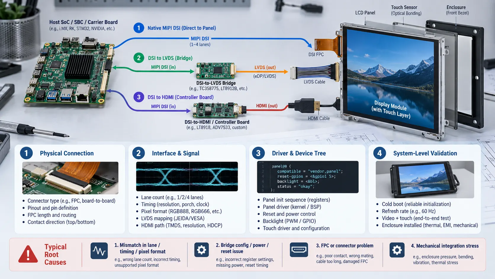
Driver and Device Tree
Review the panel driver, Device Tree node or overlay, initialization commands, reset sequence, backlight control and touch-controller driver. A panel can be electrically connected yet remain uninitialized because the operating system does not know its timing or startup sequence.
System-Level Validation
Repeat the test during cold boot, warm reboot and target refresh rate. Test video and touch together, then repeat with the final FPC route and enclosure installed. The final decision should be based on the intended product configuration rather than a single development-board result.
Root Causes Behind a Failed Display Architecture
Lane, Timing or Pixel-Format Mismatch
A lane-count or bandwidth mismatch can appear only at a higher resolution or refresh rate. Pixel format, porch values, sync width and initialization commands also affect whether the image is stable.
Bridge Configuration, Power or Reset Failure
A bridge may require specific input and output settings, power sequencing, reset timing or backlight control. These details should be checked against the bridge and panel documentation.
FPC, Connector or Signal-Integrity Problem
Incorrect pinout, contact direction, cable length, locking, bending or grounding can cause intermittent operation. The enclosure may change the result by adding mechanical stress or electromagnetic interference.
Touch Works on the Bench but Fails in the Product
Touch communication can fail while video remains normal. Check the touch controller supply, I²C or USB path, address, FPC contacts and mechanical pressure separately.
Mechanical Integration Changes the Electrical Result
Mounting points, cover-glass pressure, connector loading and cable routing can affect both signal integrity and touch behavior. Mechanical review belongs in the display architecture, not only at final assembly.
Which Fix Is Appropriate—Parameter, Module, FPC, PCBA or Structure?
Repair Parameters First
Adjust timing, lane settings, pixel format, reset, backlight or Device Tree configuration when the hardware boundary is correct and the mismatch is documented.
Change the Module When the Interface Boundary Is Wrong
Select another module when the panel interface, resolution, touch method or host capability cannot be aligned through configuration.
Change the FPC When the Panel Is Suitable but the Interconnect Is Not
Revise the FPC or connector arrangement when pinout, length, orientation, contact direction or bend routing is the problem.
Change the PCBA When Conversion or Control Logic Is Required
A modified or new PCBA may be needed for signal conversion, power control, backlight management, touch aggregation or bridge configuration.
Change the Structure When Integration Creates the Failure
Revise brackets, mounting holes, cable paths, grounding or enclosure clearances when the final mechanical assembly introduces pressure, bending or interference.
From Standard Module to Modular HMI—Which Kadi Solution Level Fits?
A standard Touch Display Module can fit a project when the interface, mechanical envelope and touch path are already defined. Kadi’s Raspberry Pi display range includes MIPI DSI-oriented modules that can be evaluated against the selected host specification.
For example, the 7.0-inch 1024×600 MIPI DSI display may be a candidate for a Raspberry Pi project, but compatibility should still be verified against the exact board, software and mechanical design.
Una Custom Display Assembly becomes more appropriate when the project requires coordinated changes to the touch layer, cover glass, optical bonding, FPC, connector, controller board or housing. Kadi’s customized display solutions describe this broader integration boundary.
When display, touch, controller electronics, cables and mechanical parts must be evaluated together, the project can move toward a Modular HMI Solution. The final scope should distinguish display hardware from host-side software, certification and system-level validation.
RFQ Checklist for a Production-Ready Display Architecture
For an architecture review, provide the information that controls the signal path:
-
Host SoC, SBC or carrier-board model
-
Operating system, BSP, kernel and current driver status
-
Display size, resolution, brightness and target refresh rate
-
MIPI DSI, LVDS or HDMI interface details
-
Lane count, timing table and pixel format
-
Touch interface and controller information
-
FPC length, connector drawing and pinout
-
Power input, reset and backlight requirements
-
Enclosure drawing, mounting points and cable route
-
Operating temperature and application environment
-
Target quantity, project stage and required validation scope
-
Fault photos or boot logs when diagnosing an existing design
Conclusión
Native MIPI DSI, DSI-to-LVDS and DSI-to-HDMI architectures can each be appropriate in different OEM designs. The practical choice is the signal path that can be verified across physical connection, interface behavior, software initialization, touch integration and final mechanical assembly.
If you are comparing a standard module with a modified assembly or a broader HMI configuration, contact Kadi Display’s technical team with the host platform, display size, resolution, interface, brightness, touch details, operating conditions, relevant drawings and any failure photos. This allows the required solution level to be evaluated without assuming compatibility from the connector name alone.
Preguntas frecuentes
Is a MIPI DSI connector enough to prove display compatibility?
No. Lane configuration, PHY behavior, timing, initialization, driver support, power sequencing and system validation must also be checked.
Does a DSI-to-HDMI bridge make every HDMI display compatible?
No. The bridge, controller board, power requirements, video timing and separate touch path must match the product architecture.
When should an OEM change the FPC instead of the display module?
Change the FPC when the selected panel and interface are suitable but the pinout, length, contact direction, connector position or mechanical route is incorrect.
What should be included in a custom display RFQ?
Include the host platform, OS and BSP, display and touch specifications, interface and timing information, FPC and connector details, mechanical drawings, operating conditions and validation requirements.
PREVIOR
No más
Siguiente
MIPI DSI Display Driver Development for Embedded Linux What Hardware Buyers Need to Confirm
Deja un comentario

Últimos blogs y noticias
- Native MIPI DSI vs LVDS or HDMI Bridge: An OEM Display Architecture Decision Guide
- MIPI DSI Display Driver Development for Embedded Linux What Hardware Buyers Need to Confirm
- Why LCD Screens Go Black Through Polarized Sunglasses and How to Prevent It
- How to Diagnose an LCD That Is Slow Flickers or Fails to Start in the Cold
- Why PCAP Touchscreens Need Retuning After Cover Glass Coating or Optical Bonding Changes
Blog y Noticias Relacionadas