




Inicio
-
Blog & Noticias
-
MIPI DSI Works on the Development Board but Not on the Custom Carrier Board: A Step-by-Step Debugging Checklist
MIPI DSI Works on the Development Board but Not on the Custom Carrier Board: A Step-by-Step Debugging Checklist
2026-08-28
00:00
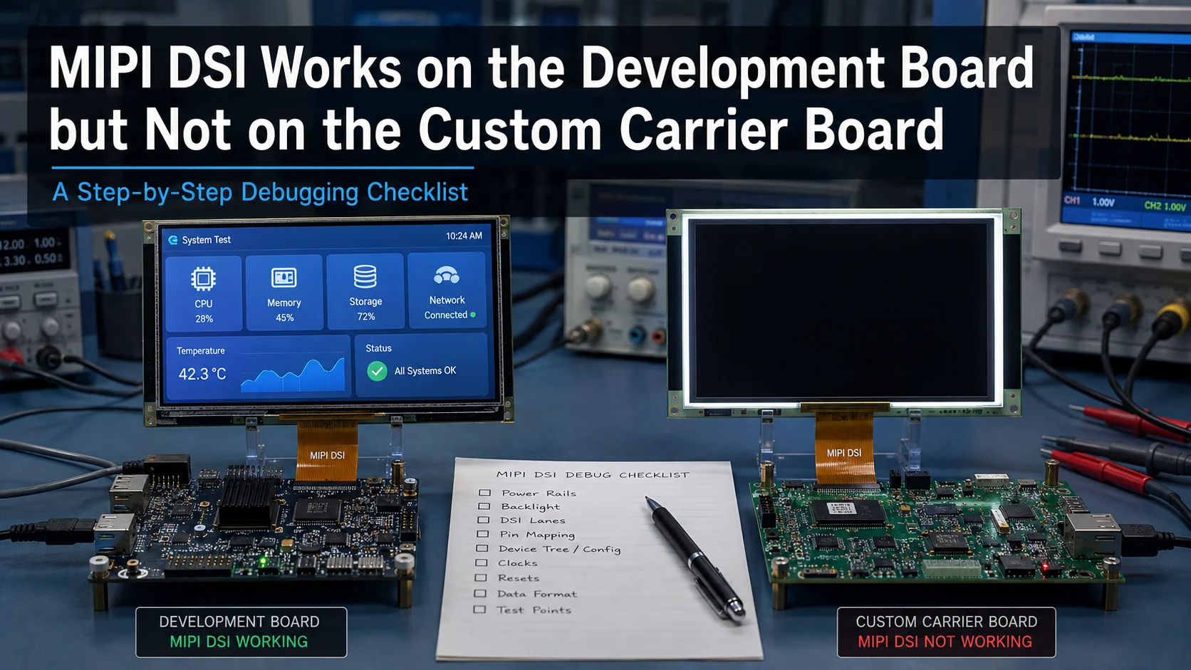
If a MIPI DSI display works on the development board but not on the custom carrier board, do not restart the entire display bring-up process. The working board is already a useful reference. The more efficient approach is to identify what changed between the known-good development platform and the failing production hardware.
Start with the physical connection, then check power and control signals, the DSI signal path, board-specific software configuration, and final mechanical integration. A matching connector or the same MIPI DSI label does not establish system compatibility; lane configuration, pinout, timing, power, initialization, driver support, and board-level implementation still need to match.
First Check: What Changed Between the Development Board and the Custom Carrier Board?
Before modifying the panel driver or trying different display timings, create a comparison between the working and failing platforms.
Keep as many variables constant as possible. Ideally, test with the same display module, the same known-good FPC where the mechanical design allows it, the same software image, and the same panel configuration. Then list everything that changed when the system moved to the custom carrier board.
Compare:
-
SoM or processor revision
-
DSI port used
-
Connector type and orientation
-
FPC or adapter design
-
DSI lane count and mapping
-
Display power rails
-
Reset, enable, and backlight controls
-
PCB routing between the host and connector
-
Device Tree or board configuration
-
BSP or kernel version
-
Touch-controller connection
-
Mechanical routing and retention of the FPC
For Raspberry Pi Compute Module designs, the carrier board is an important part of the interface implementation. Raspberry Pi’s documentation specifically covers wiring and enabling peripherals such as displays through carrier hardware and Device Tree configuration.
The key question is not simply, “Why doesn’t the display work?”
It is:
What is different between the system that works and the system that does not?
Build the Fault Tree Before You Change the Driver
The symptom can tell you which layer to investigate first. Use it to narrow the search instead of changing hardware and software simultaneously.
| Síntoma | Check First | Next Area to Check |
|---|---|---|
| No image and no backlight | Connector, power, enable signals | Carrier-board control circuit |
| Backlight on, black screen | Panel power/reset and DSI path | Driver, Device Tree, initialization |
| Panel/driver appears in Linux but no image | DSI configuration and timing | PCB/FPC signal path |
| Touch works but display is black | Display/DSI path | Do not troubleshoot touch first |
| Display works intermittently | FPC, connector, power stability | Reset behavior and signal path |
| Works in one display mode but not the target mode | Lane/timing/data-rate configuration | PCB signal integrity |
A useful distinction is that the backlight, panel logic, DSI video link, and touch controller may be separate subsystems. A lit backlight therefore does not prove that MIPI DSI video is reaching the panel.
Likewise, capacitive touch commonly uses a separate control interface rather than sharing the MIPI DSI video path, so a working touch controller does not prove the display link is operating correctly.
Test the Custom Board Against the Working Reference
Once the fault tree identifies the likely layer, compare measurable evidence between the two boards.
Start With Low-Risk A/B Checks
Before changing source code, confirm basic differences:
-
Does the exact same display module still work when returned to the development board?
-
Is the FPC inserted in the same orientation?
-
Does the custom carrier use the same DSI port and lane configuration?
-
Are the software image, kernel/BSP, driver, and panel timing unchanged?
-
Does the operating system report the expected DSI host, panel, or DRM connector?
-
Are there new boot-log errors on the custom board?
This prevents a common debugging problem: changing the driver, timing, cable, and carrier configuration at the same time and losing the working reference.
Verify Power, Reset, and Control Signals
Compare the carrier board against the exact panel, bridge, or display-module documentation.
Verify the required:
-
panel logic supplies
-
I/O supplies
-
reset signal
-
enable or standby signals
-
backlight supply and control
-
bridge or converter supplies, if used
Do not apply a generic reset delay or power sequence simply because it worked with another display. The required values and sequence should be verified against the exact panel controller or module documentation. Kadi’s existing MIPI DSI bring-up guidance follows the same evidence-based approach rather than treating generic timing values as universal requirements.
Linux Device Tree bindings also show why board-level resources matter: DSI implementations may reference regulators, resets, GPIOs, clocks, backlights, and panel endpoints as separate resources.
Root Cause 1: Connector, FPC, or Lane Mapping Changed
A connector that physically accepts the cable is not enough to establish compatibility.
Compare the complete interconnect:
-
pin count and pitch
-
contact direction
-
connector orientation
-
pin 1 position
-
DSI clock-pair routing
-
data-lane mapping
-
ground arrangement
-
panel power pins
-
reset and enable pins
-
backlight control
-
touch power and control signals, where applicable
This becomes especially important when the development setup uses an adapter board but the custom carrier connects directly to the display. The adapter may do more than change connector format; depending on the design, it may also route control signals, provide power functions, or connect other display-related circuitry.
If the panel and host are otherwise suitable but their connector assignments differ, changing the FPC or adapter can be more appropriate than replacing the entire display.
For projects built around Raspberry Pi, Kadi currently lists several Raspberry Pi MIPI DSI display modules, including touch-display configurations using MIPI DSI for display and separate touch interfaces.
Root Cause 2: Power, Reset, Backlight, or Control Signals Were Not Reproduced
A custom carrier board may reproduce the high-speed DSI lanes correctly while missing another condition required by the display.
For example, investigate whether the production board provides every supply and control signal required by the exact module. Check voltage values and sequencing against the specification, verify reset and enable polarity, and confirm that the intended GPIO is actually connected and configured.
Treat the following as separate questions:
-
Is the display logic powered?
-
Is the panel released from reset?
-
Is the backlight powered and enabled?
-
Is the DSI host transmitting the expected configuration?
-
Is the touch controller powered and communicating?
If the backlight turns on but the screen remains black, do not immediately conclude that the panel is defective or that the driver must be rewritten. The backlight circuit can operate while the panel logic or DSI path is still unavailable.
Root Cause 3: The DSI Host Configuration or PCB Signal Path Changed
If the physical pinout and basic power sequence are correct, compare the DSI configuration.
Verify the exact project requirements for:
-
data-lane count
-
lane assignment
-
DSI operating mode
-
pixel format
-
panel timing
-
initialization requirements
-
required data rate
The development board may already prove that a particular panel configuration can work with the host platform, but the custom carrier creates a new electrical path between the host and display.
That path should be reviewed against the processor or SoM vendor’s hardware design guidance, the display specification, connector documentation, and the actual PCB stack-up. Avoid relying on a universal trace-length, impedance, or skew number when the relevant hardware documentation specifies project-dependent requirements.
For Compute Module designs, this distinction matters because the MIPI interface must ultimately be implemented through the carrier hardware. Raspberry Pi’s CM5 documentation, for example, specifies the available MIPI interfaces and provides hardware design information for carrier-board implementation.
If you are still choosing the display architecture rather than debugging an existing board, Kadi Display provides TFT, touchscreen, Raspberry Pi, embedded, and customized-display product paths that can be evaluated against the host and application requirements.
Root Cause 4: The Panel Driver Is the Same, but the Board Configuration Is Not
A driver that works on the development board is useful evidence, but it does not prove that the new carrier requires no software changes.
On Linux-based systems, the panel driver and board-specific configuration have different responsibilities. The Device Tree may describe how the panel is attached to the DSI host and how regulators, GPIOs, backlight controls, or other resources are connected. The Linux DRM documentation explicitly includes mechanisms for matching DSI hosts and devices described through Device Tree.
For a custom carrier board, verify:
-
Is the intended DSI host enabled?
-
Is the panel attached to the correct endpoint?
-
Are regulator references valid?
-
Do reset and enable GPIOs match the new PCB?
-
Is GPIO polarity correct?
-
Is the correct backlight node referenced?
-
Does the design include a bridge or converter that needs its own configuration?
-
If touch is present, is its I²C or USB path configured independently?
This is where “the same display and the same driver” can still produce different behavior on two boards.
A practical example of a more integrated path is Kadi’s 10.1-inch 1200×1920 MIPI DSI display for Raspberry Pi CM4/CM5, whose current product page describes a converter-board architecture and Linux driver/Device Tree setup for that specific product. It should be treated as a product-specific implementation, not as proof that the same configuration applies to another panel or custom carrier.
Root Cause 5: Touch or Mechanical Integration Is Hiding the Real Problem
If display operation changed only after the assembly moved into a prototype enclosure, inspect the physical installation as well.
An FPC may follow a different bend path, sit under tension, or lose reliable retention when the display is mounted in the final structure. A touchscreen can also introduce its own wiring, grounding, power, reset, and control requirements.
Separate these paths during diagnosis:
-
If the image works and touch fails, investigate the touch subsystem.
-
If touch works and the image fails, return to the DSI display path.
-
If the fault changes when the assembly is moved or pressed, inspect connector engagement, cable routing, and mechanical stress before changing display parameters.
The production device is the final compatibility test. Electrical operation on an open development bench does not validate the complete mechanical assembly.
Fix the Right Layer: Parameters, FPC, Display Module, PCBA, or Mechanical Design?
The objective of debugging is not only to identify the cause. It is to determine the smallest appropriate change.
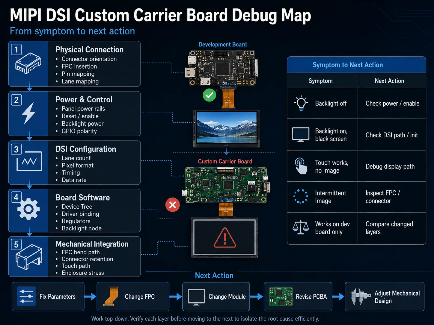
If the evidence points to incorrect lane count, timing, Device Tree resources, or initialization, correct the configuration before redesigning hardware.
If the panel is electrically suitable but the custom carrier uses a different connector or pin assignment, evaluate an FPC or adapter change.
If the project requires a different touch stack, connector arrangement, cover glass, interface arrangement, or mechanical format, a modified or customized display solution may reduce the number of separate adaptations around a standard panel. Kadi’s current customized-display page publicly lists options around interfaces, thickness, brightness, wide-temperature requirements, AD-board compatibility, and enclosure choices; the exact feasibility still depends on the project specification.
If the carrier board lacks a required bridge, power function, or interface circuit, the PCBA architecture may need revision instead.
And if the display works electrically but cannot be integrated reliably into the enclosure, solve the mechanical interface rather than continuing to tune software.
The important rule is simple: fix the layer where the evidence points.
Which Display Integration Level Fits the Project?
Not every carrier-board problem requires a fully custom display.
A standard touch display module can be appropriate when the host interface, pinout, software support, mechanical envelope, and environmental requirements already align.
A modified or custom display assembly becomes more relevant when the project needs changes around FPC routing, connector placement, touch integration, cover glass, or mechanical arrangement.
A more modular HMI or display-system architecture may be worth evaluating when the project is accumulating several interface adaptations around the panel—for example a display, touch controller, converter or controller PCBA, Linux/SBC platform, and enclosure that all need to work together.
The decision should be based on the exact host, display specification, mechanical constraints, software environment, and production architecture rather than the connector label alone.
What Information Should You Prepare Before Requesting a Display or Integration Review?
If the fault cannot be resolved within the existing architecture, prepare the information that defines both the working reference and the failing system.
Useful project information includes:
-
host processor, SoC, or SoM model
-
development-board model
-
custom carrier-board revision
-
display or module part number
-
target display size and resolution
-
available connector and pinout information
-
MIPI DSI lane configuration
-
OS, BSP, or kernel version where relevant
-
exact symptom on the custom carrier board
-
whether display and touch fail together or independently
-
available display datasheet, timing, or initialization information
-
mechanical drawing or available installation space if the assembly may need modification
There is no need to disclose information that cannot be shared. Provide the relevant project details that are available.
Conclusión
When a MIPI DSI display works on the development board but fails on a custom carrier board, use the working platform as the baseline instead of restarting from zero. Compare the changed layers in order: physical connection, power and control, DSI configuration, board-specific software, and mechanical integration.
The result should guide the next action—change parameters, modify the FPC, select a different display module, revise the carrier PCBA, or reconsider the display assembly architecture.
If your project requires a different FPC, connector arrangement, display module, or integration approach, you can contacto con Kadi Display with the host platform, display specification, available pinout information, software environment, failure symptom, and relevant mechanical constraints to discuss suitable display options. Compatibility and required modifications should be verified against the exact host, display, carrier-board design, and software configuration.
Preguntas frecuentes
Why does a MIPI DSI display work on an evaluation board but not on my custom PCB?
The custom PCB may have changed the connector pinout, lane routing, power rails, reset or enable controls, board-specific Device Tree configuration, or high-speed signal path. Use the working evaluation board as the reference and compare only the variables that changed.
Does the same MIPI DSI connector mean the display is compatible?
No. Physical mating is only one part of compatibility. The host and display must also be checked for pinout, lane configuration, supported data rate and timing, power and reset requirements, initialization, software support, and complete-system operation.
If the backlight is on but the display is black, is the MIPI DSI link working?
Not necessarily. Backlight power can be separate from panel logic and DSI video transmission. Check panel power/reset, driver binding, Device Tree configuration, DSI initialization, and the physical signal path before assuming that the panel is receiving valid video.
Should I redesign the FPC or change the driver first?
Follow the evidence. If the carrier-board pinout or physical signal routing differs from the working reference, investigate the FPC or board interconnect. If the physical and electrical paths match but the panel is not binding or initializing correctly, investigate software and board configuration first.
When should I consider a custom display assembly instead of a standard MIPI DSI module?
A custom or modified assembly becomes more relevant when a suitable panel still requires changes such as a different FPC or connector arrangement, touch integration, cover glass, or mechanical format. If the only problem is a software parameter or Device Tree error, changing the display assembly may add unnecessary complexity.
PREVIOR
MIPI DSI Image Is Present but Corrupted: Pixel Format, Timing, Driver, and Signal-Path Checks
Siguiente
MIPI DSI Worked Before the Linux Update but Is Black Now: Driver, Device Tree, and Kernel Checks
Deja un comentario

Últimos blogs y noticias
- Electronic Component Obsolescence Management for Industrial Displays: An OEM Guide
- How to Develop a Production Ready Custom Display Assembly TFT Module Touch Cover Glass FPC Bonding and Mounting
- 15 Pin vs 22 Pin Raspberry Pi DSI Connectors Cable Pinout and Compatibility
- Native MIPI DSI vs LVDS or HDMI Bridge: An OEM Display Architecture Decision Guide
- MIPI DSI Display Driver Development for Embedded Linux What Hardware Buyers Need to Confirm

