




Accueil
-
Blog & Actualités
-
How to Read a MIPI DSI Timing Table: Pixel Clock, Porches, Sync Width, and Refresh Rate
How to Read a MIPI DSI Timing Table: Pixel Clock, Porches, Sync Width, and Refresh Rate
2026-08-07
00:00
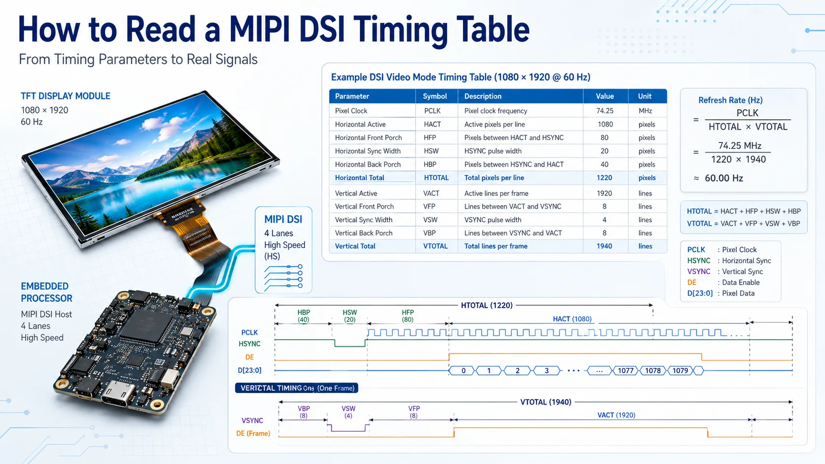
To read a MIPI DSI timing table, identify the active horizontal and vertical resolution, then add the front porch, sync width, and back porch to calculate the complete horizontal and vertical totals. Those totals allow you to verify the stated pixel clock and refresh rate before configuring the host processor, Linux panel driver, or Device Tree.
A timing table is ready for use only when its values are complete, mathematically consistent, and supported by the host. Resolution alone is not enough, and two panels with the same resolution may require different timing.
What Should a Complete MIPI DSI Timing Table Contain?
A usable panel timing table should identify both the visible image area and the blanking periods around it.
Look for:
-
HACT or HActive
-
HFP, or horizontal front porch
-
HSW, HSA, or horizontal sync width
-
HBP, or horizontal back porch
-
VACT or VActive
-
VFP, or vertical front porch
-
VSW, VSA, or vertical sync width
-
VBP, or vertical back porch
-
Pixel clock
-
Refresh rate
-
Minimum, typical, and maximum values where applicable
-
Units for every parameter
HACT and VACT define the active resolution. The remaining values define the timing intervals between active lines and frames.
The timing table should be reviewed together with the panel’s lane count, pixel format, video or command mode, driver IC, and initialization requirements. Those parameters are not all part of the timing calculation, but they determine whether the timing can be used on the intended MIPI DSI link.
A datasheet that lists only “1024 × 600 at 60 Hz” does not provide enough information to configure a panel reliably.
How to Read the Horizontal Timing
Horizontal timing describes one complete display line.
The sequence is generally:
-
Active image pixels
-
Front porch
-
Horizontal sync interval
-
Back porch
-
The next active line
HACT
HACT is the number of visible pixels in each line. For a 1024 × 600 display, the horizontal active value is normally 1024.
HFP
The horizontal front porch is the number of pixel-clock periods between the end of the active image and the beginning of horizontal sync.
HSW
Horizontal sync width is the duration of the horizontal synchronization interval, measured in pixel-clock periods.
Some datasheets use HSA instead of HSW. The exact terminology may vary, but the function is similar.
HBP
The horizontal back porch is the number of pixel-clock periods between the end of horizontal sync and the start of the next active line.
Calculate the total horizontal timing with:
HTotal = HACT + HFP + HSW + HBP
The host must generate the complete HTotal, not only the active width. Changing any porch or sync value changes the total number of pixel periods in every line.
That can affect:
-
Required pixel clock
-
Actual refresh rate
-
MIPI DSI bandwidth
-
Image position
-
Link stability
Do not copy horizontal timing from another panel merely because the active resolution is the same.
How to Read the Vertical Timing
Vertical timing follows a similar structure but is measured in lines rather than individual pixel clocks.
The sequence is generally:
-
Active display lines
-
Vertical front porch
-
Vertical sync interval
-
Vertical back porch
-
The next active frame
VACT
VACT is the number of visible lines in each frame. For a 1024 × 600 display, the vertical active value is normally 600.
VFP
The vertical front porch is the number of lines between the final active line and the beginning of vertical sync.
VSW
Vertical sync width is the number of lines occupied by the vertical synchronization interval.
VBP
The vertical back porch is the number of lines between the end of vertical sync and the first active line of the next frame.
Calculate the total vertical timing with:
VTotal = VACT + VFP + VSW + VBP
Vertical blanking cannot be ignored. A higher VTotal increases the number of pixel periods required for each complete frame, even though the visible resolution does not change.
Reducing a porch value may appear to lower the required clock or increase the refresh rate, but the change is acceptable only when the panel specification permits it.
How to Verify Pixel Clock and Refresh Rate
Once HTotal and VTotal are known, the timing can be checked in both directions.
Calculate Pixel Clock
Use:
Pixel Clock = HTotal × VTotal × Refresh Rate
The result is expressed in hertz and is often converted to megahertz.
For Linux DRM, the mode’s clock field is generally expressed in kilohertz. The DRM display-mode structure also uses fields such as hdisplay, hsync_start, hsync_end, htotal, and the corresponding vertical values to describe the complete timing.
Calculate the Actual Refresh Rate
When the datasheet provides a pixel clock, verify its relationship to the timing:
Refresh Rate = Pixel Clock ÷ (HTotal × VTotal)
This calculation helps identify:
-
A pixel clock that does not match the claimed refresh rate
-
A timing value entered in the wrong unit
-
A missing porch or sync interval
-
A typical clock that produces 59.9 Hz rather than exactly 60 Hz
-
A host clock that is slightly different because of PLL limitations
Worked Example
The following values are for calculation practice only. They are not specifications for a Kadi product.
| Paramètre | Example value | Calculation role |
|---|---|---|
| HACT | 1024 | Active horizontal pixels |
| HFP | 160 | Horizontal front porch |
| HSW | 20 | Horizontal sync width |
| HBP | 140 | Horizontal back porch |
| VACT | 600 | Active vertical lines |
| VFP | 12 | Vertical front porch |
| VSW | 3 | Vertical sync width |
| VBP | 20 | Vertical back porch |
| Target refresh rate | 60 Hz | Desired frame rate |
The totals are:
HTotal = 1024 + 160 + 20 + 140 = 1344
VTotal = 600 + 12 + 3 + 20 = 635
The required pixel clock is:
1344 × 635 × 60 = 51,206,400 Hz
The result is approximately 51.21 MHz.
If the host generates 51.20 MHz instead, the resulting refresh rate is approximately 59.99 Hz. Whether that difference is acceptable depends on the panel’s permitted clock range and the host configuration.
How to Interpret Minimum, Typical, and Maximum Values
Panel datasheets may provide minimum, typical, and maximum values for pixel clock, porch intervals, sync widths, or refresh rate.
The typical configuration is usually the safest starting point, but it should not be treated as a universal rule. The datasheet may define a recommended mode separately or specify which parameters can vary.
Avoid combining unrelated extremes, such as:
-
Minimum HFP
-
Maximum HBP
-
Typical HSW
-
Maximum pixel clock
That mixture may create a timing combination the panel supplier did not intend.
Supplier clarification is appropriate when:
-
The typical pixel clock does not match the typical timing
-
The minimum and maximum columns do not form complete modes
-
The permitted refresh-rate range is unclear
-
Timing units are missing
-
Sync polarity is not defined
-
The timing table conflicts with the reference driver
-
The initialization file appears to use another display mode
Do not approve the panel based on an internally inconsistent table.
Can Porch and Sync Values Be Adjusted?
Porch and sync values can sometimes be adjusted, but only within the panel’s supported limits.
An adjustment may be considered when:
-
The host cannot generate the exact pixel clock
-
The display controller has register limits
-
A supported refresh rate requires a different total
-
The platform documentation recommends a specific timing arrangement
Any adjustment can change:
-
HTotal or VTotal
-
Pixel clock
-
Actual refresh rate
-
Required MIPI DSI data rate
-
Blank-packet behavior
-
Panel stability
The MIPI interface specification does not replace the exact panel timing requirements. The division of horizontal blanking into front porch, sync, and back porch remains dependent on the panel and host configuration.
If the datasheet does not provide an acceptable range, request confirmation rather than treating blanking intervals as arbitrary values.
How to Map the Timing Table to Linux DRM
A panel timing table can be translated into a Linux drm_display_mode as follows:
-
hdisplay = HACT
-
hsync_start = HACT + HFP
-
hsync_end = HACT + HFP + HSW
-
htotal = HACT + HFP + HSW + HBP
-
vdisplay = VACT
-
vsync_start = VACT + VFP
-
vsync_end = VACT + VFP + VSW
-
vtotal = VACT + VFP + VSW + VBP
-
clock = pixel clock in kHz
Linux defines these fields as part of its internal display-mode structure, which specifies the timing attached to the display pipeline.
For example, a panel driver may define one preferred drm_display_mode and expose it through get_modes(). Another integration may represent the timing through Device Tree fields such as:
-
clock-frequency
-
hactive
-
hfront-porch
-
hsync-len
-
hback-porch
-
vactive
-
vfront-porch
-
vsync-len
-
vback-porch
The exact implementation depends on the panel driver and host architecture. Some MIPI DSI panels keep the mode inside the C driver because they also require panel-specific initialization commands.
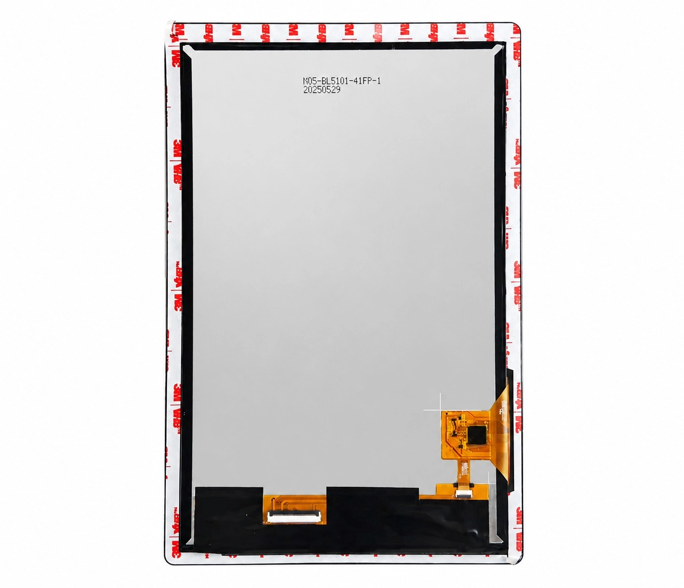
Le 10.1-inch 1200×1920 MIPI DSI touchscreen for Raspberry Pi CM4 is relevant as an integration example because its product page identifies the resolution, MIPI DSI display interface, and Raspberry Pi-oriented configuration. Its exact timing should still be taken from the applicable panel documentation or driver rather than inferred from the resolution.
How to Check Whether the Host Can Use the Timing
A timing table may be internally correct and still be unsuitable for the target host.
Confirm:
-
Minimum and maximum supported pixel clock
-
Whether the host PLL can generate the required clock accurately
-
Maximum horizontal and vertical totals
-
Supported refresh-rate range
-
Lane count
-
Pixel format
-
Per-lane bandwidth
-
Video or command mode
-
Supported sync behavior
Timing approval should therefore produce two separate conclusions:
-
The panel timing is internally consistent.
-
The host can generate and transport that timing.
Readers evaluating embedded Linux, LVGL, Qt, or other processor-based projects can review embedded MIPI DSI display solutions when comparing available integration paths. Kadi’s product structure includes embedded solutions alongside display modules, Raspberry Pi products, accessories, and customized-display options.
Timing Compatibility Is Not Complete-System Compatibility
Correct timing is necessary, but it does not confirm that the complete display system will operate.
The project must also check:
Physical connection
-
Connector pitch and contact direction
-
FPC pinout
-
Clock- and data-lane mapping
-
Cable routing and enclosure space
Electrical requirements
-
Panel and I/O voltage
-
Reset and enable signals
-
Backlight supply
-
Power sequence
Software support
-
Panel driver
-
Initialization commands
-
Device Tree
-
Kernel or BSP support
-
Touch-controller driver
System validation
-
Cold boot
-
Restart
-
Image stability
-
Suspend and resume
-
Touch mapping
-
FPC clearance
If incorrect timing produces a black screen, shifted image, flicker, or unstable startup, the MIPI DSI display troubleshooting guide provides a broader path covering interface, driver, initialization, and system-level checks.
How to Approve or Reject a Timing Table Before Ordering
Classify the result before approving a panel.
Ready for Host Configuration
Use this result when:
-
All required timing fields are present
-
HTotal and VTotal are correct
-
Pixel clock and refresh rate agree
-
The host supports the required clock and totals
-
Lane, format, and operating mode are defined
Supplier Confirmation Required
Use this result when:
-
Minimum, typical, and maximum values are unclear
-
The driver and timing table disagree
-
The host clock is close to the panel limit
-
Sync polarity or units are missing
-
The initialization mode is not identified
Do Not Approve Yet
Use this result when:
-
Only the active resolution is provided
-
Porch or sync values are missing
-
Pixel clock and refresh rate conflict
-
The panel model or driver IC is unidentified
-
The host clearly cannot generate the required timing
Standard Module, Custom Assembly, or Modular Solution?
A standard module is appropriate when the timing, driver, interface, FPC, touch, and mechanical format already match the host platform.
A modified module or custom display assembly may be more practical when the core MIPI DSI interface is suitable but the project requires:
-
A different FPC or pinout
-
Modified panel-driver timing
-
Another touch controller
-
Cover glass or optical bonding
-
Mechanical adaptation
-
A project-specific adapter board
When low-level timing and driver integration are outside the project scope, a controller-based or modular display solution can provide a more standardized system interface.
Affichage Kadi offers product paths spanning TFT and touch modules, Raspberry Pi displays, embedded solutions, accessories, and customized displays rather than limiting development to a bare panel.
Conclusion
A MIPI DSI timing table should be read in a fixed sequence: identify the active resolution, add the horizontal and vertical porch and sync values, calculate HTotal and VTotal, and verify the relationship between pixel clock and refresh rate.
The result must then be mapped to the host or Linux display mode and checked against the processor’s clock, lane, format, and bandwidth limits. A correct timing table does not by itself prove physical, electrical, driver, touch, or complete-system compatibility.
When a timing table is incomplete or inconsistent, use review a MIPI DSI panel timing requirement and submit the host or mainboard model, exact panel model, timing table, pixel-clock range, target refresh rate, lane count, pixel format, connector information, operating system, application, and expected quantity.
Questions fréquentes
How Do I Calculate Pixel Clock from a MIPI DSI Timing Table?
Add the active area, front porch, sync width, and back porch to calculate HTotal and VTotal. Multiply both totals by the target refresh rate.
What Is the Difference Between Front Porch and Back Porch?
The front porch occurs after the active image and before sync. The back porch occurs after sync and before the next active image area.
Can I Change Porch Values to Reach 60 Hz?
Only when the values remain within the panel’s permitted range and the resulting pixel clock, bandwidth, and host configuration remain valid.
Why Does a Panel with the Correct Resolution Show a Shifted Image?
The active resolution may be correct while the pixel clock, porch, sync width, or total timing does not match the panel.
Is a Correct Timing Table Enough to Approve the Panel?
No. Lane count, bandwidth, connector pinout, power, initialization commands, driver support, Device Tree, touch, and system validation must also be checked.
Précédent
Can You Reuse a MIPI DSI Display Across SBCs and SoMs? A Host Migration Checklist
Suivant
Existing Driver, Driver Modification, or New Driver? How to Check a Raspberry Pi CM4 MIPI DSI Panel Before Ordering
Laisser un commentaire

Derniers blogs et nouvelles
- MIPI DSI Display Works at Room Temperature but Fails After Warm-Up: A Troubleshooting Workflow
- LCD Prototype Passed but Pilot Units Fail: A Display Integration Isolation Workflow
- VESA vs JEIDA LVDS Mapping: Evidence-Based Color Diagnosis and Release
- eDP LCD Panel Integration: Power, AUX, Link Training, Video and Backlight
- How to Choose an LCD Controller Board: Architecture, EDID, Timing and Latency

