Casa
-
Blog & Notizie
-
USB Touchscreen Keeps Disconnecting in an Industrial HMI: A Fault-Isolation Workflow
USB Touchscreen Keeps Disconnecting in an Industrial HMI: A Fault-Isolation Workflow
2026-09-25
00:00
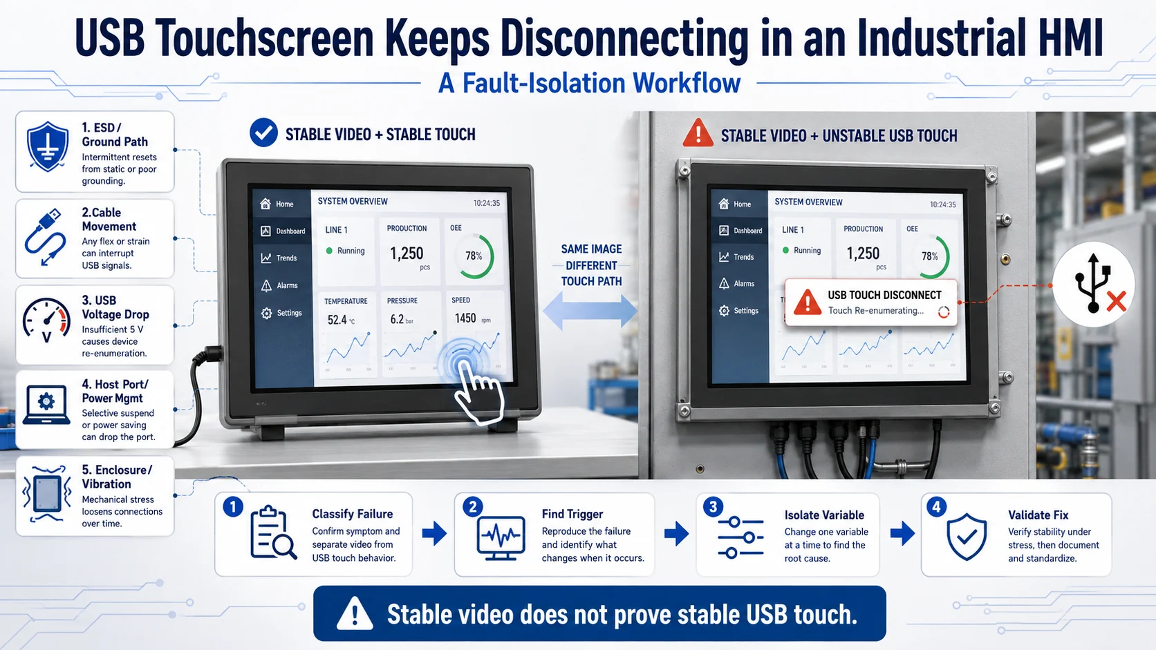
If a USB touchscreen keeps disconnecting in an industrial HMI, do not replace the touch module before confirming what the host actually records. ESD, ground shift, cable movement, USB voltage drop, host-port behavior, or software power management can all reset the touch controller. First determine whether the USB device disappears, disconnects and re-enumerates, or remains connected but stops sending input events. Those symptoms require different tests and different corrective actions.
Is the USB Touchscreen Disconnecting or Only Becoming Unresponsive?
A touchscreen that no longer responds is not necessarily disconnected. Classify the failure before changing hardware:
-
USB disconnect: The device disappears from the host.
-
Disconnect and re-enumeration: The host reports removal followed by a new connection or reset.
-
Input-event failure: The USB device remains present, but no touch events reach the operating system.
-
Touch-performance fault: The controller remains connected but produces ghost touches, drift, dead zones, or incorrect coordinates.
Video and touch are normally separate paths. An HDMI, LVDS, eDP, or MIPI DSI image may continue normally while the USB touch controller resets. A stable image therefore does not prove that touch power, USB data, or grounding is stable.
Record the failure time, whether reconnecting the cable restores touch, whether the device identifier changes, and whether the fault occurs during sleep, load changes, enclosure contact, or cable movement.
Quick Check: Does the Fault Follow the Touch Device, Host, or Installation?
Use tools appropriate to the operating system to review USB connection events, enumeration messages, driver binding, device identity, input events, and power-management status. Follow the documentation for the exact Windows, Linux, or embedded platform version rather than applying unrelated commands.
Next, look for a repeatable trigger. Does the disconnect occur when an operator touches the cover glass or metal bezel? Does it coincide with a relay, motor, inverter, solenoid, backlight change, CPU load, sleep transition, vibration, or rising temperature?
A failure linked to touching the enclosure points toward an ESD or ground-path investigation. A failure caused by moving the cable suggests retention, strain, or conductor damage. A disconnect during peak system load may indicate USB power or shared-rail behavior. If only one host port is affected, the host PCBA becomes a stronger suspect.
Build the USB Touchscreen Fault Tree
USB touchscreen compatibility must be checked at four levels: physical connection, electrical interface, software support, and complete-system behavior.
Physical Connection
Confirm connector type, insertion, retention, cable length, routing, strain relief, adapters, hubs, and FPC transitions. Check whether the enclosure bends the USB cable, prevents complete insertion, or transfers vibration into the connector.
A matching USB connector confirms physical fit only. It does not establish cable quality, current margin, signal integrity, driver support, or assembled-system compatibility.
USB Power, Signal, and Grounding
Review the touch controller’s power requirements and the host port’s available supply. Check whether the controller voltage changes during the disconnect, especially when the backlight, processor, or another USB device changes load.
Map the relationships among USB signal ground, USB shield, controller ground, LCD frame, chassis ground, and the metal enclosure. Shield termination should be selected for the actual system. A single-ended or double-ended connection is not a universal solution.
ESD can enter through the cover glass, bezel, connector, or exposed metal and disturb the touch controller or host USB port. The important question is where the discharge current returns and whether that path crosses sensitive USB or touch circuitry.
Driver and Complete-System Support
Check driver binding, touch-controller firmware, USB autosuspend, sleep recovery, host-controller behavior, and recent OS or kernel changes. Temporarily changing a documented power-management setting may help isolate the fault, but it cannot correct unstable power, poor grounding, or cable problems.
Validation must use the intended host, controller board, display load, USB topology, cable route, enclosure, and application.
Test One Variable at a Time
Begin with a known-good baseline: a verified host port, short USB cable, stable power, unchanged software, and an open-bench assembly. Remove unnecessary adapters and hubs. Then introduce the production cable, controller board, power architecture, and enclosure individually.
| Test Result | Likely Fault Branch | Next Check |
|---|---|---|
| Device disappears and returns in USB logs | Reset, power, cable, ESD, or host port | Correlate the event with its trigger |
| Device remains present but events stop | Driver, firmware, application, or controller state | Inspect raw input events |
| Fault follows the USB cable | Cable, connector, shielding, or strain | Review cable and routing |
| Fault stays with one host port | Host power, protection, routing, or controller | Compare another verified port |
| Fault starts after enclosure assembly | Ground path, ESD, cable strain, or structure | Compare open and assembled units |
| Powered hub changes the result | Host-port power or ground relationship | Investigate the source condition |
A powered hub can help separate host-port power from touch-controller behavior, but it should be treated as a diagnostic tool unless it is intentionally included and validated in the final architecture.
When measuring power, observe the voltage at the touch controller during the event rather than relying only on the supply’s nominal rating. Measurement points and acceptable limits must come from the relevant controller and host specifications.
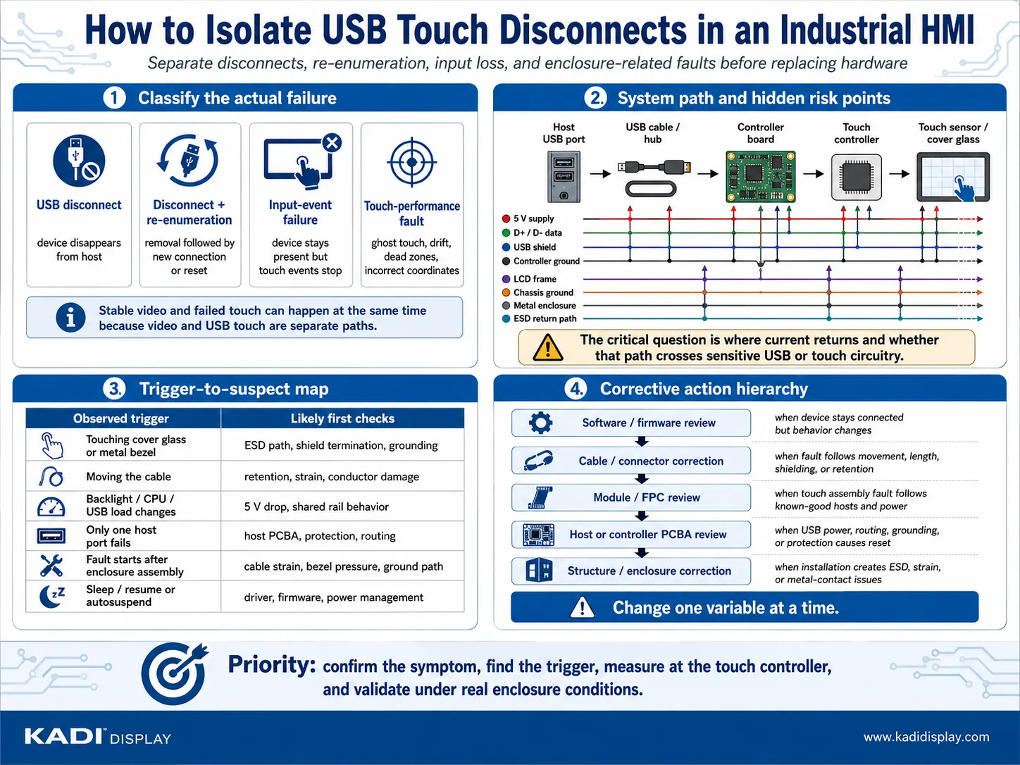
Match the Root Cause to the Correct Fix
For an ESD-related reset, review the discharge path, chassis connection, shield interface, protection placement, and separation from sensitive signals. Do not add grounding straps, ferrites, or protection components without considering the complete current path and PCBA layout.
When the failure follows the cable, correct its length, construction, routing, bend, connector retention, or strain relief as supported by the evidence. Keep USB wiring away from high-current switching loops where the mechanical design permits.
When the controller voltage drops, review shared power rails, connector loss, load transients, and host-port capability. A software workaround should not conceal inadequate power margin.
If the USB device remains enumerated but input stops, investigate the driver, firmware, application, and resume behavior before redesigning the structure. Conversely, repeated hardware resets in the system log should not be treated only as an application problem.
Il industrial display stack-up design guide provides additional context for coordinating the LCD, touch sensor, PCB, FPC, grounding interfaces, and enclosure.
When to Tune Parameters, Replace the Module, or Redesign Hardware
Choose the lowest change level supported by the test evidence:
-
Tune software or firmware: The electrical connection remains stable, and the fault follows driver binding, power management, controller settings, or sleep recovery.
-
Replace the USB cable or connector: The fault follows cable movement, length, retention, shielding, or connector condition.
-
Replace or modify the Touch Display Module: The failure follows the touch controller or assembly across known-good hosts, power, and cables.
-
Modify the FPC: Evidence identifies FPC strain, pinout, connector position, or the controller-to-sensor connection.
-
Modify the host or controller PCBA: The USB port, controller power, routing, grounding, protection, or connector placement causes the reset.
-
Modify the structure: The failure appears only after installation and follows bezel pressure, metal contact, cable strain, or an uncontrolled ESD return path.
After any correction, repeat cold-start, sleep-resume, full-load, cable-movement, assembled-system, and application-relevant ESD/EMC checks.
Choose the Appropriate Display Solution Level
A standard touch module can be appropriate when its controller, USB interface, cable, power, cover glass, and mechanical interfaces already match the equipment. The industrial TFT touch displays category provides configurations with capacitive or resistive touch and USB or I2C touch options.
A specific product should be considered only when its published specifications match the project. For example, the 10.1-inch HDMI monitor with USB touch lists a 1280×800 display, HDMI video input, USB touch interface, and 800-nit brightness. Compatibility with a particular host, enclosure, and operating environment still requires verification.
A modified module may address cable, connector, FPC, cover glass, bonding, or touch-controller requirements. When the LCD, touch, controller, cable, bracket, grounding, and enclosure interfaces must be controlled together, a Custom Display Assembly may be more appropriate.
A Modular HMI Solution or Complete Display System becomes relevant when the host interface, power architecture, controller board, mechanical mounting, and system validation are also part of the required boundary. Display Kadi should therefore be evaluated according to the integration level needed, not only as a bare-panel source.
Prepare the Technical Package for an RFQ or Failure Review
Useful project information includes:
-
Host platform and operating system
-
Touch-controller or USB device identification
-
USB logs around the failure
-
Display and touch specifications
-
USB cable length, connector, and routing
-
Power architecture
-
Video and touch interfaces
-
Grounding or stack-up drawing
-
Enclosure drawing
-
Repeatable fault trigger
-
Fault photos or videos
-
Application and expected quantity
Conclusione
A random USB touch failure should first be classified with USB and input-event evidence. Once the fault is shown to follow software, cable, power, host PCBA, touch assembly, or enclosure, the team can make a focused correction instead of replacing unrelated parts.
For a display-side review, contatto Kadi Display with the host platform, touch-controller information, USB logs, cable details, power architecture, stack-up drawing, fault trigger, application, and quantity.
Domande frequenti
Why Does the Display Keep Working When USB Touch Disconnects?
Video and touch commonly use separate interfaces. The image path may remain active while the USB touch controller loses power, resets, or disconnects from the host.
Can Disabling USB Autosuspend Fix the Problem?
It may help diagnose a power-management or resume problem. It does not fix ESD, grounding, cable, power-supply, or PCBA faults.
Does a USB Disconnect Mean the Touch Module Is Defective?
No. The cause may be the cable, host port, power rail, driver, PCBA, grounding arrangement, enclosure, or touch controller. Controlled substitution is needed before replacing the module.
Can a Matching USB Connector Confirm Compatibility?
No. The connector must be evaluated together with power, USB signaling, controller support, driver behavior, cable construction, and complete-system validation.
PREVIDENTE
Non più
Prossimo
HDMI Monitor Works on a Laptop but Not an SBC: EDID, HPD, and Timing Checks
Lascia un commento

Ultimi Blog & Notizie
- USB Touchscreen Keeps Disconnecting in an Industrial HMI: A Fault-Isolation Workflow
- HDMI Monitor Works on a Laptop but Not an SBC: EDID, HPD, and Timing Checks
- MIPI DSI Display Works at Room Temperature but Fails After Warm-Up: A Troubleshooting Workflow
- LCD Prototype Passed but Pilot Units Fail: A Display Integration Isolation Workflow
- Display Bridge IC Selection: Direction, Bandwidth, Features and Productization
Blog & Notizie correlate