




Huis
-
Blog & Nieuws
-
MIPI DSI Power Sequencing and Reset Timing Check: Why a Compatible Panel Can Still Show a Black Screen
MIPI DSI Power Sequencing and Reset Timing Check: Why a Compatible Panel Can Still Show a Black Screen
2026-08-21
15:39
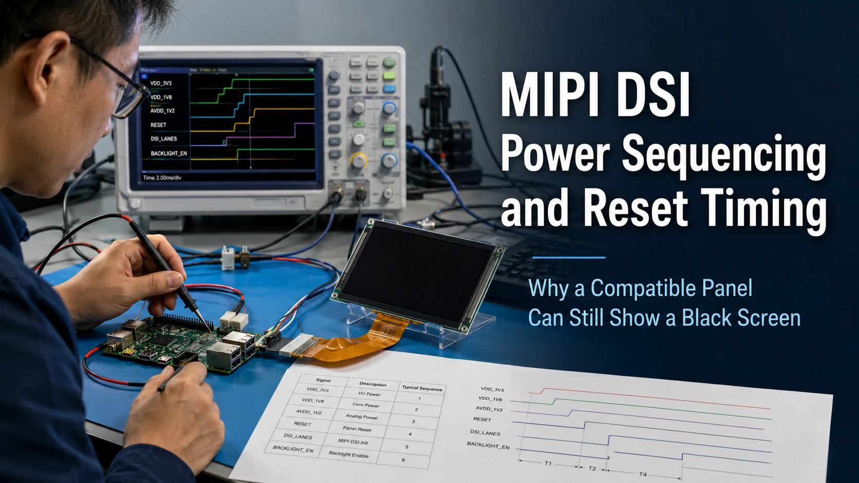
A panel can match the host connector, pinout, lane count, resolution, and timing yet remain black if the MIPI DSI power sequencing and reset timing are wrong. The startup path must coordinate panel rails, DSI-host readiness, hardware reset, initialization commands, video transmission, display enable, and backlight control. Required delays and signal levels are panel-specific, so they should come from the exact module specification, driver IC documentation, board schematic, and software implementation—not from a similar display.
First Confirm That the Failure Is a Startup-Sequence Problem
Before changing delays, classify the symptom and reconfirm the minimum compatibility conditions. A black screen can result from sequencing, but it can also come from a reversed FPC, wrong lane mapping, unsuitable timing, missing initialization commands, an incorrect Device Tree node, or a panel driver that does not bind. The complete MIPI DSI black-screen troubleshooting guide treats these as separate failure layers.
Classify What the System Actually Does
Record whether there is no power, backlight without an image, a brief image flash, operation only after warm reboot, operation only after a full power cycle, or different results after driver reload or resume. Also record whether touch works independently.
Backlight activity confirms only that part of the backlight path may be active. Touch activity may confirm an I²C, SPI, or USB path, but it does not confirm that DSI video is running.
Reconfirm the Minimum Compatibility Conditions
Verify the exact board revision, module part number, FPC orientation, pinout, DSI lane count, panel timing, operating mode, voltage rails, and software support. A matching connector or resolution does not establish system compatibility. The MIPI DSI display compatibility checklist separates compatibility into physical connection, electrical and signal configuration, software support, and complete-system operation.
If one of these conditions is unresolved, correct it before treating power or reset timing as the primary cause.
Build the Required Power-On Timeline from the Exact Specifications
Create a panel-specific timeline rather than applying a generic delay sequence.
Identify Every Event in the Startup Path
Map the sequence from the first valid supply to visible image output:
-
Host and panel rails become stable.
-
The DSI host or PHY enters the required state.
-
Hardware reset is asserted and released.
-
The specified post-reset interval expires.
-
Panel-specific initialization commands are sent.
-
Sleep Out is issued when required.
-
Video or command mode starts.
-
Display On is issued when required.
-
Backlight enable and PWM become active.
-
The touch controller is initialized.
The module specification may require a different order or additional events. Use the exact documentation as the controlling source.
Include Shutdown, Reboot, and Resume
Also map backlight-off, display-disable, sleep commands, reset assertion, DSI shutdown, and rail removal. A warm reboot may leave a rail charged or preserve bootloader state, while a cold boot starts from a discharged system. Suspend and resume may use another software path.
Verify the Power Rails Under Real Startup Conditions
Measure the panel rails and control signals during the actual failure. Code review cannot show whether a regulator rises slowly, drops under load, pulses unexpectedly, or leaves residual voltage after shutdown.
Measure Each Supply Separately
Relevant signals may include panel logic, I/O and backlight rails, regulator enables, hardware reset, panel enable, backlight enable, and PWM. Compare voltage, rise behavior, rail order, and discharge behavior with the product specification. Check whether GPIO or DSI signals become active while the panel is unpowered, which can create an unintended current path.
A software delay cannot correct an incorrect voltage, insufficient GPIO level, unstable rail, or unsuitable fixed regulator order. Those conditions may require a host-board, adapter-board, or power-control change.
Compare Cold Boot with Warm Reboot
Capture the same signals during a full power cycle, software reboot, driver reload, and suspend/resume. Align the waveforms with boot logs or GPIO timestamps.
If the panel works after reboot but not cold boot, investigate whether the DSI host, regulators, or reset line become ready in a different order. If it works only after a cold boot, the panel may not be fully reset or discharged during reboot.
Check Reset Polarity, Pulse Width, and Release Timing
Reset is both an electrical signal and a timed event. Confirm its active level, voltage thresholds, GPIO drive capability, pull state, pulse width, state while panel power is absent, and delays before and after release.
Measure at the module or connector where possible. Routing, level shifting, buffering, and default GPIO states can make the waveform at the panel different from the intended software state.
Separate Hardware Reset from Software Reset
A physical reset input resets panel or driver-IC hardware. A MIPI DCS software-reset command is transmitted only after communication is available. A software command may be part of initialization, but it should not replace a required hardware reset.
Also check whether the bootloader and kernel both toggle reset, whether two drivers reference the same GPIO, or whether resume uses a sequence different from cold boot.
Verify DSI Host Readiness and Panel Initialization Order
Some failures occur because the panel is powered correctly but the DSI host is not ready when commands are sent.
Determine When the DSI Host Must Be Prepared
Review low-power command communication, PHY state, lane assignment, and the transition to high-speed video. Linux DRM documentation includes a prepare_prev_first condition for cases where the preceding controller should be prepared before the panel; it notes this is largely required for DSI panels whose host must reach LP-11 before panel power-up.
The correct order is therefore not necessarily “power the panel, then initialize the host.”
Confirm the Complete Initialization Sequence
Check the required manufacturer registers, MIPI DCS commands, Sleep Out, pixel format, address mode, Display On, and video-mode activation. Do not copy an initialization table only because another display uses a similar driver IC. Glass timing, lane configuration, power design, and vendor programming may differ.
Driver logs and return codes show whether software attempted the sequence. Command traces, GPIO timing, or correlated current changes can provide additional evidence.
Map the Timeline to the Linux Panel Driver and Device Tree
For Linux systems, each startup event should belong to a defined driver stage.
Use the DRM Panel Lifecycle
The Linux DRM panel interface separates four operations: prepare() turns on and sets up the panel; enable() enables visible operation; disable() turns off visible output; and unprepare() powers the panel down.
This separation supports a controlled order between power/reset preparation and backlight enable. If the backlight starts before initialization completes, the user may see a black or unstable screen.
Check Device Tree and Bootloader Dependencies
Review the panel compatible string, DSI host status, data lanes, regulators, reset polarity, enable GPIO, backlight node, display timing, and touch-controller node. Device Tree describes hardware relationships but does not supply missing panel-specific commands.
Establish whether the bootloader initializes the display before Linux. The kernel may reset a panel that the bootloader left running, or it may assume a state that does not exist after cold power-on. Compare bootloader, kernel, shutdown, and resume paths separately.
Keep Backlight and Touch Outside the DSI Image Diagnosis
| Observed condition | What it may confirm | What it does not confirm |
|---|---|---|
| Backlight on | Backlight power and enable are active | Panel initialization or DSI video |
| Backlight off | Backlight path is inactive | DSI commands are absent |
| Touch works | Touch power, bus, and driver may be active | DSI image path is correct |
| Image works, touch fails | Panel image path is operating | Touch wiring and driver are configured |
| Brief image flash | Some display activity occurred | Stable, repeatable startup |
A platform-oriented module such as the 10.1-inch MIPI DSI touch display for embedded SBCs combines a defined display interface with an I²C touch path. Its published information supports initial evaluation for the named platforms, but the exact board revision, power architecture, driver, and startup sequence still require project-level confirmation.
Decide Whether to Change Software, Hardware, or the Display Architecture
Choose the next action from measured evidence.
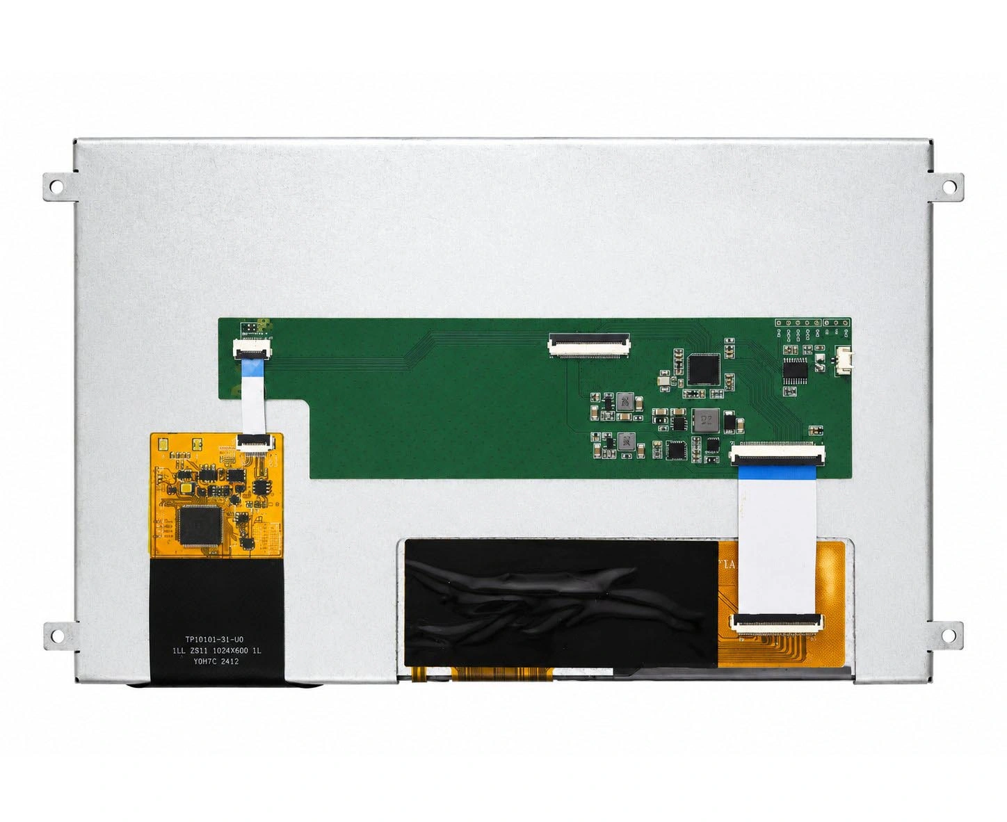
A driver or Device Tree update is appropriate when electrical signals meet the specification and the host can control the sequence. Changes may include GPIO polarity, regulator order, driver delays, initialization commands, or lifecycle callbacks.
A host-board or adapter-board change may be needed when reset voltage is unsuitable, rails cannot be controlled independently, the backlight starts too early, or the panel is back-powered through signal lines.
A modified module or custom display assembly may be more suitable when the DSI link is usable but the project needs a revised FPC, connector, touch arrangement, backlight architecture, PCBA, cover lens, bonding, or mounting structure.
Where native DSI integration creates an unsuitable dependency on host drivers or power control, a modular HMI or controller-based route may provide a clearer system boundary. Kadi Display’s industrial display and integration solutions can be reviewed according to the host interface, software environment, mechanical constraints, and required integration level.
Validate the Complete Startup and Shutdown Cycle
After implementing a change, test cold boot after full discharge, warm reboot, repeated power cycling, shutdown and immediate restart, suspend/resume, backlight changes, and touch initialization. Where required by the device specification, also review startup at intended voltage and temperature limits.
Record the board and panel revisions, driver and Device Tree versions, measured timing, boot logs, failure frequency, and differences between cold and warm startup. Stop adding arbitrary delays when the panel specification is unavailable, a rail is unstable, reset polarity is unresolved, initialization data belongs to another panel, or the host cannot control the required sequence.
The goal is not merely to illuminate the screen once. It is to determine whether the Touch Display Module, host board, power architecture, software, and mechanical assembly form a repeatable Complete Display System.
Conclusie
MIPI DSI power sequencing should be verified as a complete timeline: power integrity, host readiness, hardware reset, panel initialization, video transmission, display enable, backlight, touch, and shutdown behavior. Connector, pinout, lane, and timing matches do not establish reliable startup by themselves.
If a panel works only after reboot, shows backlight without an image, or fails during cold boot or resume, discuss your MIPI DSI startup requirements with Kadi Display. Useful inputs include the host platform and board revision, exact display part number, connector or schematic, power/reset timing information, operating system and BSP version, boot logs, and failure photos or waveforms.
Veelgestelde vragen
Why does a MIPI DSI display work after reboot but not cold boot?
A warm reboot may preserve regulator charge, bootloader initialization, GPIO state, or DSI-host configuration that is absent during cold boot. Compare power rails, reset, host readiness, and command timing across both states.
How long should reset be held on a MIPI DSI panel?
There is no universal duration. Use the exact module or driver-IC specification and measure the pulse at the panel input. Also verify the delays before reset release and before the first initialization command.
Should the backlight turn on before or after panel initialization?
Backlight control is normally treated as a separate visible-output stage. The required order should follow the module and system documentation. Early backlight enable can expose a black screen without identifying whether the panel or DSI link initialized.
Can adding a longer delay fix a MIPI DSI black screen?
It can reveal or mask a race condition, but it cannot correct an unsuitable voltage, wrong reset polarity, missing initialization command, incompatible timing, unavailable driver, or uncontrolled regulator sequence. Tie delay changes to documented requirements or measured dependencies.
Voorgaande
MIPI DSI Worked Before the Linux Update but Is Black Now: Driver, Device Tree, and Kernel Checks
Volgende
Can Your Host and Panel Support MIPI DSI Command Mode? An Embedded HMI Selection Checklist
Laat een reactie achter

Laatste Blog & Nieuws
- MIPI DSI Display Driver Development for Embedded Linux What Hardware Buyers Need to Confirm
- Why LCD Screens Go Black Through Polarized Sunglasses and How to Prevent It
- How to Diagnose an LCD That Is Slow Flickers or Fails to Start in the Cold
- Why PCAP Touchscreens Need Retuning After Cover Glass Coating or Optical Bonding Changes
- Why Outdoor LCDs Fog Inside: Condensation, Sealing, Vents, and Heaters

