




Can Industrial LCD Screens Burn In? Myths and Facts About LCD Image Retention
2026-07-19
05:45
Can Industrial LCD Screens Burn In?
Myths and Facts About LCD Image Retention
A plain-language explainer separating the real physics of LCD image retention from the OLED and CRT burn-in folklore it is often confused with — and what that distinction actually means for industrial HMI and kiosk displays.
Por Equipe Técnica da Kadi Display | www.kadidisplay.com
A Question That Gets the Wrong Answer Most of the Time
“Can an LCD burn in?” is one of the most commonly searched questions about industrial displays, and it almost always gets answered with information borrowed from OLED or plasma technology — display types that genuinely do burn in, through a completely different physical process than anything happening inside an LCD panel. The confusion is understandable. “Burn-in” became a household term in the plasma TV era and was reinforced by years of OLED smartphone and television marketing warning about the same phenomenon. When a fixed mark eventually shows up on an LCD-based industrial HMI after years of continuous service, it is natural to reach for the same explanation.
The honest answer is more nuanced and more useful: LCD panels do not burn in the way OLED, plasma, or CRT displays do, but they are capable of a related-looking phenomenon called image retention, also called image sticking or transient ghosting, that has an entirely different cause, a different relationship to permanence, and different prevention strategies. Conflating the two leads to two opposite mistakes — assuming an LCD is immune to any static-image risk, or assuming an LCD will suffer the same permanent pixel damage an OLED does under the same usage pattern.
This guide separates the physics carefully: how true burn-in actually destroys material in CRT, plasma, and OLED displays; how LCD image retention works through a completely different and usually reversible mechanism; why industrial HMI and kiosk applications are the use case where this distinction matters most in practice; and the specific design choices that keep LCD-based industrial displays free of visible retention across a multi-year service life.
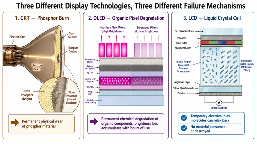
How Real Burn-In Actually Works in CRT, Plasma, and OLED Displays
The term “burn-in” earned its name honestly in CRT and plasma displays, where the failure mechanism involves literal, permanent consumption or alteration of the material that produces light. Understanding this mechanism by contrast is what makes the LCD distinction clear.
CRT — Phosphor Wear
A cathode ray tube produces an image by firing a focused electron beam at a phosphor-coated screen, causing the phosphor to fluoresce. Phosphor compounds have a finite number of fluorescence cycles before their light-emitting efficiency degrades — a property called phosphor aging. When the same image, such as a station logo, a paused video frame, or a software toolbar, is displayed in the same screen position for thousands of hours, the phosphor in that specific location wears down measurably faster than phosphor elsewhere on the screen. The result is a literal, permanent, physical change to the phosphor coating. There is no software fix and no amount of time will reverse it, because the phosphor compound itself has been consumed.
Plasma — Similar Phosphor Mechanism
Plasma displays use a related but distinct phosphor-based light emission process, and they inherited the same fundamental vulnerability: sustained, localized excitation of phosphor cells causes those specific cells to degrade in luminous efficiency faster than the rest of the panel. Plasma burn-in became infamous in the 2000s specifically because uniform content such as news tickers, network logos, and video game HUDs was displayed in fixed positions for the typical multi-hour viewing sessions that drove plasma TV adoption.
OLED — Organic Material Degradation
OLED displays use organic compounds that emit light directly when current passes through them — no backlight, no phosphor, and each pixel self-illuminating. These organic compounds degrade chemically with cumulative current exposure, a property the display industry tracks formally through luminance half-life ratings. A pixel that has been illuminated more cumulative hours than its neighbors literally emits less light per unit of drive current than those neighbors — a permanent, irreversible reduction in luminous efficiency that becomes visible as a ghost image when uniform content is displayed.
All three of these mechanisms — CRT phosphor wear, plasma phosphor wear, and OLED organic degradation — share one structural feature: the light-producing material itself is permanently altered or consumed by use. This is why true burn-in does not recover with time, software reset, or any non-physical intervention. The compound that used to emit light efficiently has been chemically or physically changed, and no amount of waiting restores it.
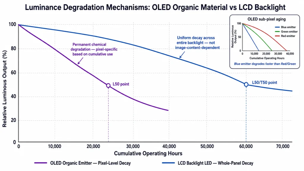
Why LCD Panels Work on a Completely Different Principle
An LCD does not produce its own light at the pixel level at all — this single architectural fact is the root of every difference described in this guide. A liquid crystal display consists of a backlight that produces uniform white light, and a liquid crystal layer in front of it that acts as a controllable optical shutter, twisting polarized light to allow more or less of that backlight through at each pixel location. The liquid crystal molecules themselves do not emit anything. They only modulate light that is already there.
This means the failure mode that defines true burn-in — light-emitting material being consumed or chemically altered by use — has no direct equivalent in an LCD’s actual image-forming layer. The liquid crystal compound used in industrial TFT panels does not fluoresce, does not carry current as an emitter, and is not chemically transformed by the act of displaying an image. What can happen to an LCD, and what is responsible for the image retention this guide focuses on, is a much more limited and largely reversible phenomenon involving electrical bias rather than material consumption.
The Mechanism: Ion Migration and Capacitive Bias
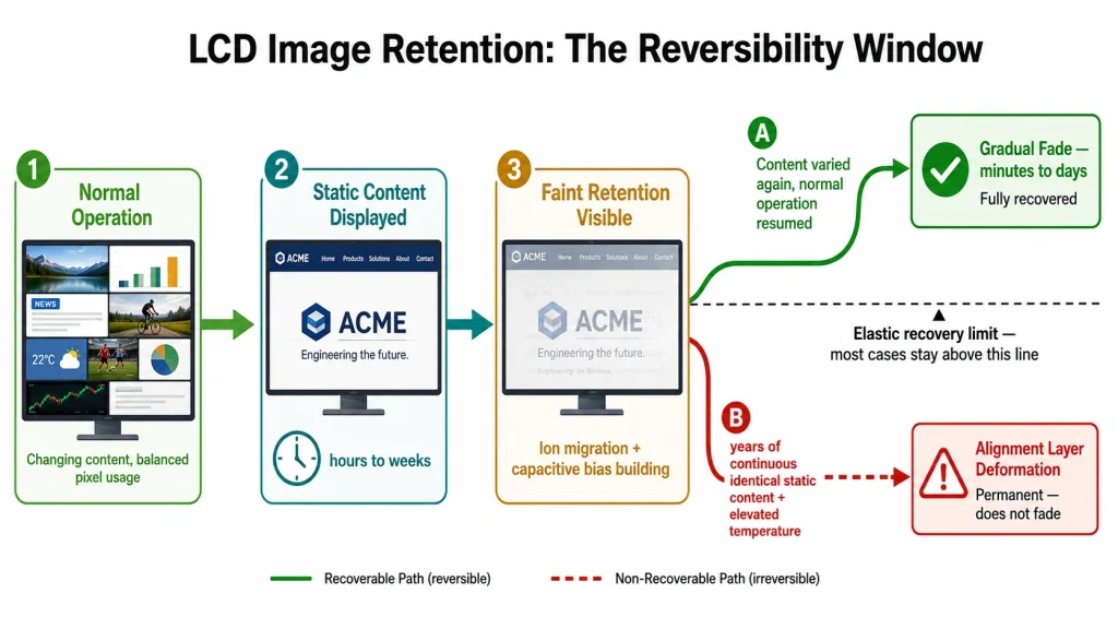
Each LCD pixel is driven by a voltage applied across the liquid crystal layer to achieve a specific tilt angle, which determines how much light passes through. When the exact same voltage pattern is held at the exact same pixel for an extended period — a static UI element, a fixed logo, or a navigation bar that never changes — two related effects can occur. First, trace ionic impurities naturally present in the liquid crystal fluid can slowly migrate toward one electrode under sustained directional electrical bias, accumulating into a residual charge distribution that persists briefly even after the driving voltage changes. Second, the pixel’s thin-film-transistor storage capacitor can experience a small, gradual shift in its effective threshold voltage from prolonged identical charge cycling.
Both effects bias the liquid crystal’s resting state toward whatever it was most recently and consistently asked to display. When the displayed content then changes, that lingering bias shows up as a faint shadow of the old image — the visual symptom that gets called LCD “burn-in” in casual usage, even though nothing has burned, melted, or been chemically consumed.
Why It Is Usually Reversible — and Sometimes Is Not
The critical practical difference from true burn-in: ion migration and capacitive bias are electrical and chemical equilibrium effects, not material destruction. If the static image is removed and normal varying content resumes, the ionic distribution gradually re-equilibrates and the capacitive bias relaxes, typically over a period ranging from several minutes to a few days depending on how long the static condition was sustained. This is why LCD image retention is frequently described as “it went away after I left it off overnight” — a description that would never apply to genuine OLED or CRT burn-in.
The exception, and the reason image retention prevention still matters for industrial HMI design, is sustained exposure beyond the liquid crystal alignment layer’s elastic recovery limit. Years of continuous identical static content, particularly combined with elevated operating temperature, can eventually cause the microscopically grooved polyimide alignment layer that orients the liquid crystal molecules to suffer a small, localized, non-recoverable deformation. At that point the retention becomes effectively permanent — not because anything was chemically consumed the way OLED material is, but because a mechanical or electrical equilibrium was pushed past the point of full recovery.
Five Myths About LCD Burn-In, Corrected
MYTH 1: LCD screens burn in exactly the same way OLED screens do
FACT: LCD and OLED share a visual symptom — a faint ghost image — but not a mechanism. OLED burn-in is permanent chemical degradation of organic light-emitting compounds; the affected pixels physically emit less light per unit of current forever. LCD image retention is a temporary electrical or ionic bias in a layer that does not emit light at all. The backlight does that separately and uniformly. The LCD’s liquid crystal material is not consumed by displaying an image, however static.
MYTH 2: If you see a faint mark on an LCD, it is permanently damaged
FACT: In the substantial majority of reported LCD retention cases, the mark fades within minutes to a few days once varied content resumes, because the underlying ionic and capacitive bias relaxes back toward equilibrium. Genuinely permanent LCD retention is a real but less common outcome, typically requiring years of continuous identical static content combined with elevated operating temperature — not the kind of static content exposure a typical user encounters in days or weeks.
MYTH 3: LCDs are completely immune to any static-image risk
FACT: This is the opposite overcorrection, and it is also wrong. While LCD retention is usually reversible, industrial HMI displays running 24/7 with truly static UI elements for years — common in factory control panels and kiosk navigation bars — do carry a real, non-zero risk of eventually crossing into the less-reversible category, particularly in elevated-temperature enclosures. This is precisely why industrial display engineering practices like periodic pixel-shift and frame or column inversion driving schemes exist as standard mitigation.
MYTH 4: A higher-resolution or more expensive LCD panel will not show retention
FACT: Resolution and price have no direct bearing on retention resistance. What matters is the liquid crystal fluid formulation, the TFT driving scheme, and the panel’s qualification for sustained static-image use. A premium consumer 4K monitor optimized for color accuracy can show retention faster than a lower-resolution industrial panel specifically engineered with retention-resistant driving electronics for HMI applications.
MYTH 5: Turning the screen off occasionally prevents all retention risk
FACT: Powering off does not address the root cause — sustained identical voltage at specific pixels — it only interrupts exposure time. Software-level mitigation that actually changes pixel content periodically, such as subtle pixel-shift routines or scheduled inversion of static UI elements, is significantly more effective than simple power cycling, because it reduces the cumulative duration of identical bias at any single pixel rather than just pausing the clock on a fixed schedule.
Why the LCD-vs-OLED Distinction Matters Specifically for Industrial HMI
Industrial HMI and kiosk applications are, structurally, the worst-case scenario for any retention-prone display technology — and simultaneously the application where understanding the LCD/OLED distinction has the most practical consequence. A factory SCADA panel, a payment kiosk navigation frame, or an equipment status display commonly shows the same fixed layout elements continuously for years, running 24 hours a day without the content variation that naturally protects consumer displays used for browsing, video, or gaming.
This is exactly the usage pattern that would make OLED burn-in a serious, fast-developing concern — which is one practical reason OLED remains uncommon in industrial HMI applications despite its superior contrast and viewing angle characteristics. LCD’s fundamentally different, largely reversible retention mechanism is part of why LCD-based TFT panels remain the dominant industrial display technology for fixed-content, long-duty-cycle HMI applications, alongside LCD’s other industrial advantages: wider proven temperature ranges, simpler and more mature supply chains, and backlight degradation that is uniform and gradual rather than image-content-dependent.
Practical Prevention — Keeping LCD Retention in the Reversible Zone
Because LCD retention risk scales with cumulative static exposure time and operating temperature, the practical engineering goal for a long-life industrial HMI is not eliminating risk to zero — it is keeping any retention that does develop comfortably inside the reversible zone, so it never has the opportunity to progress toward the rare but real permanent outcome.
- Specify a retention-resistant LC driving scheme. Frame inversion or column inversion driving — which periodically reverses pixel voltage polarity — directly counteracts the sustained directional bias that drives ion migration. This should be confirmed explicitly with the panel supplier rather than assumed from a general “industrial grade” label.
- Build periodic pixel-shift into the HMI application software. Shifting static UI elements by a pixel or two on a scheduled interval meaningfully reduces cumulative identical-bias time at any single pixel, without being visually perceptible to operators.
- Avoid maximum-contrast static elements where the UI design allows it. A pure-white icon on pure black, held in a fixed position, represents a worst-case driving condition; muted contrast in static UI elements reduces both the underlying bias magnitude and the visibility of any resulting artifact.
- Respect the panel’s rated operating temperature with margin. Ion mobility increases with temperature, so a panel run consistently near the top of its rated range accumulates retention risk faster than the same panel run with thermal margin — this is the same temperature sensitivity that governs LCD response time and contrast performance more broadly.
📌 Temperature Is the Hidden Multiplier on Retention Risk
Both the speed at which retention develops and the temperature at which an LCD operates are connected through the same underlying ion mobility physics — sustained operation near the top of a panel’s rated temperature range measurably accelerates the ionic migration responsible for image retention, in addition to its already well-documented effects on response time, contrast, and long-term liquid crystal alignment. Specifying a wide-temperature panel with comfortable thermal margin for the actual enclosure environment is one of the most effective, lowest-cost mitigations available at the hardware selection stage.
Sourcing LCD Panels Engineered Against Retention for 24/7 HMI Use
The driving scheme, temperature rating, and backlight quality that determine LCD retention resistance are specification details that do not always appear on a standard catalog listing, but they are exactly what separates an industrial-grade panel from a relabeled consumer part for any HMI application running continuously for years.
Kadi Display’s guide on wide-temperature TFT displays for industrial applications explains how sustained high temperature accelerates liquid crystal alignment degradation and contributes to the kind of image retention discussed in this guide, alongside the industrial-grade LC fluid and driving circuit choices that extend a panel’s safe operating margin to −30°C to +85°C. Their broader industrial display brightness selection guide notes specifically that sustained operation above 70°C at the glass surface leads to contrast loss, color shift, and eventually permanent image retention — underscoring why panel surface temperature, not just ambient temperature, is the figure that actually matters for retention risk management.
For HMI and medical-grade applications requiring confirmed 50,000+ hour backlight lifetime alongside retention-resistant panel construction, Kadi Display’s overview of industrial LCD displays in medical device applications covers the backlight longevity and wide-temperature specifications relevant to any 24/7 continuous-duty HMI deployment, not just medical-specific use cases.
Referência de produto e suporte técnico
For industrial TFT-LCD display modules engineered with retention-resistant driving schemes, wide-temperature LC formulations, and confirmed long-term backlight lifetime for 24/7 HMI and kiosk applications, contact Kadi Display at Sales@sz-kadi.comServiços OEM e ODM disponíveis. Browse wide-temperature industrial TFT-LCD displays →
Summary — Same Word, Different Physics, Different Stakes
“LCD burn-in” is a phrase borrowed from a different display technology to describe a phenomenon that works through a fundamentally different mechanism. CRT, plasma, and OLED displays burn in because their light-emitting material is permanently consumed or chemically altered by use — there is no recovery, ever. LCD panels experience image retention through a largely reversible ionic and capacitive bias in a liquid crystal layer that does not emit light at all, which is why most LCD retention fades on its own and why the failure mode only becomes genuinely permanent under sustained, multi-year static exposure combined with elevated temperature.
For engineers and procurement teams specifying displays for industrial HMI and kiosk applications, this distinction translates directly into design priorities: confirm the panel’s LC driving scheme, build pixel-shift mitigation into the application software, respect temperature margin, and treat LCD retention risk as a manageable engineering parameter rather than either an irrelevant myth or an unavoidable certainty borrowed from OLED folklore.
Isenção de responsabilidade: Technical explanations, lifetime figures, and degradation timelines in this guide are general industry reference information intended for educational purposes and must be verified against specific panel manufacturer datasheets for any given product. Actual retention behavior, recovery time, and backlight lifetime vary by manufacturer, LC fluid formulation, driving circuit design, and operating conditions. All brand and product names are the property of their respective owners. No affiliation with any third-party display technology provider is implied.
PRIVENTE
Automotive-Grade TFT LCD Displays: How to Choose a Rugged Screen for Harsh Vehicle Environments
NEXTO
ESP32-S3 RGB Display with GT911 and LVGL: A Practical Guide for Kiosk and HMI Applications
Deixe um comentário

Recent Blog & News
- Industrial LCD EOL: What Happens from Pre-Announcement to Replacement Mass Production?
- Electronic Component Obsolescence Management for Industrial Displays: An OEM Guide
- How to Develop a Production Ready Custom Display Assembly TFT Module Touch Cover Glass FPC Bonding and Mounting
- 15 Pin vs 22 Pin Raspberry Pi DSI Connectors Cable Pinout and Compatibility
- Native MIPI DSI vs LVDS or HDMI Bridge: An OEM Display Architecture Decision Guide

