GT911 Touchscreen Not Working with LVGL? A Hardware and Software Checklist
2026-06-28
13:09
GT911 Touchscreen Not Working with LVGL?
A Hardware and Software Checklist
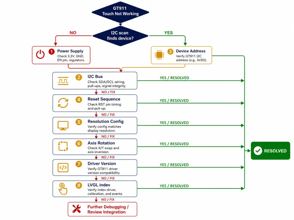
Eight diagnostic areas — power supply, I²C bus, device address, reset sequence, resolution mapping, axis rotation, driver version, and LVGL indev registration — with specific tests, error patterns, and verified fixes
Por Equipe Técnica da Kadi Display | www.kadidisplay.com
Introduction — Why GT911 + LVGL Debugging Feels Like Guesswork
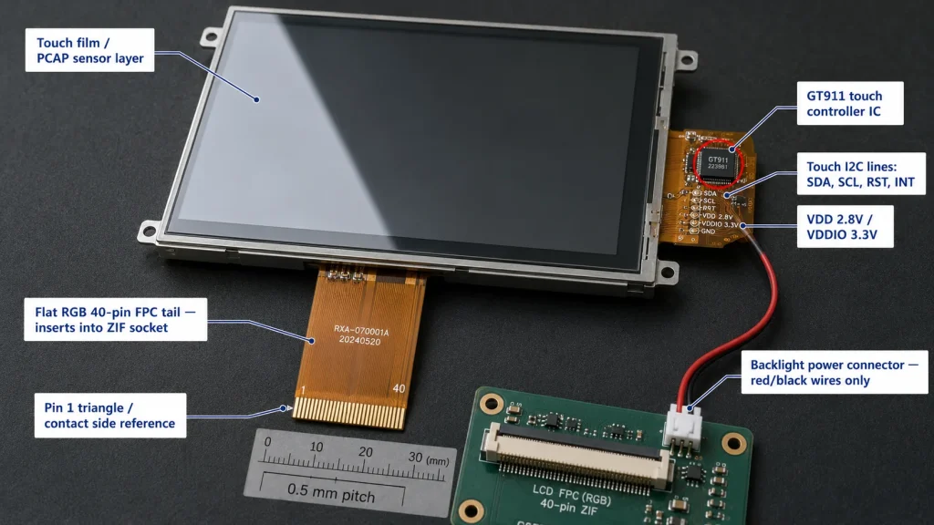
The GT911 capacitive touch controller is one of the most capable ICs in its class. It supports up to five simultaneous touch points, handles gesture recognition in firmware, communicates over a well-documented I²C protocol, and has been shipping in mass-market display modules for well over a decade. None of that stops it from being completely silent when something in the bring-up sequence goes wrong — and when it is silent, every symptom looks identical: no touch events, ever, regardless of what you press.
The LVGL side compounds this. LVGL’s input device abstraction (lv_indev_drv_t) cleanly separates the UI framework from hardware — which is architecturally correct but means a misconfigured touch registration, a missing mutex, or an incorrect coordinate mapping produces the same user-visible symptom as a completely dead touch controller. Touch works at the hardware level. LVGL sees nothing. The log shows no errors.
This checklist covers eight diagnostic areas in the order you should investigate them. Each area has a specific test that confirms or rules it out, the error pattern it produces, and the exact fix. Work through them in sequence — earlier failures often mask later ones, and jumping ahead wastes time.
CHECKLIST 1 Power Supply
VDD, VDDIO, rail noise, startup sequencing
Power problems are the least glamorous and the most commonly overlooked cause of GT911 failure. The chip has two separate supply pins with different voltage requirements, and both must be stable before the reset sequence begins.
1-A VDD Supply Voltage — Wrong Rail or Wrong Level
GT911 VDD is specified at 2.8 V ± 0.3 V (2.5 V to 3.1 V). Many display modules require a dedicated 2.8 V LDO fed from the system 3.3 V rail. If VDD is directly connected to 3.3 V without a regulator, the chip may operate intermittently — functioning at room temperature but failing at elevated temperature as internal protection engages.
→ Fix:
Measure VDD at the GT911 chip pin under operational load. Target: 2.8 V ±5%. If the module routes VDD directly from 3.3 V, consult your panel supplier for VDDIO-only 3.3 V operation compatibility notes.
1-B VDDIO Supply — Logic Level Mismatch
GT911 VDDIO controls logic thresholds for I²C SDA, SCL, RST, and INT. VDDIO 1.8 V is common in MIPI DSI display modules; VDDIO 3.3 V is standard in RGB LCD modules. If VDDIO is 1.8 V but the host drives RST and INT at 3.3 V logic levels, the GT911 may interpret both pins as permanently HIGH — causing incorrect address selection and potential pin stress.
→ Fix:
Verify VDDIO voltage at the GT911 pin. If VDDIO = 1.8 V, all GPIO connections must come from a 1.8 V GPIO bank or through a bidirectional level shifter. Use TXS0104E or equivalent for I²C level translation. Series resistors alone are insufficient for bidirectional I²C level shifting.
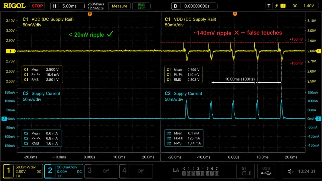
1-C Supply Rail Ripple — Noise During Active Scanning
GT911 active scanning draws 30–80 mA from VDD in bursts at the touch report rate (up to 100 Hz). On a shared switching regulator rail, this produces 50–150 mV of ripple. Ripple above ±100 mV causes false touch detections or complete loss of touch registration.
→ Fix:
Test: Probe VDD at the GT911 pin with a 200 MHz oscilloscope while touching the panel. Ripple > ±100 mV peak-to-peak = power problem. Fix: Add 10 Ω series resistor + 10 µF electrolytic + 100 nF ceramic to GND within 5 mm of the VDD pin. This ~1.6 kHz LPF attenuates switching noise by 40+ dB.
CHECKLIST 2 I²C Bus
Pull-up resistors, bus speed, signal integrity, scan test
I²C failures are the second most common GT911 bring-up issue. The protocol is simple on paper — two wires, address, data — but the physical bus has strict signal integrity requirements that a logic probe won’t reveal.
2-A Missing or Wrong Pull-Up Resistors
I²C is open-drain — without pull-up resistors, SDA and SCL float at indeterminate voltages and every transaction returns NACK. At 400 kHz, the spec requires max rise time of 300 ns. With 50 pF bus capacitance, minimum pull-up value ≈ 300 ns / 50 pF ≈ 6 kΩ. Resistors above 10 kΩ at 400 kHz produce slow rising edges that fail under any additional bus capacitance.
→ Fix:
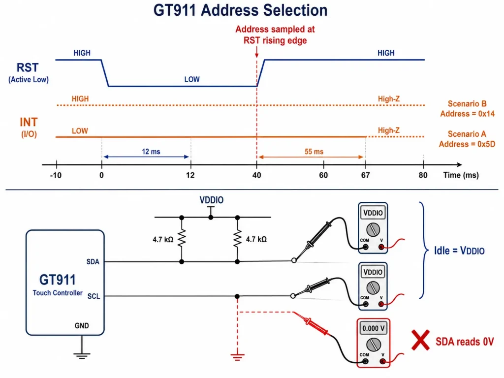
SDA and SCL must idle HIGH at VDDIO level when no transaction is in progress. If they idle LOW or float, pull-ups are missing or on wrong rail. Use 4.7 kΩ to VDDIO for 400 kHz; 2.2 kΩ if cable length exceeds 150 mm.
2-B Eu²C Bus Scan Returns Nothing
Run an I²C bus scan. Expected: response at 0x5D ou 0x14. If scan finds nothing at either address, GT911 hasn’t completed initialization or I²C signals aren’t reaching the chip.
→ Fix:
- First: Confirm power stable (CL1) before assuming I²C fault.
- Second: Measure SDA and SCL with a multimeter. Both must read VDDIO at idle. If either reads 0 V, open circuit or GPIO misconfiguration.
- Third: Slow I²C to 100 kHz and retry. Marginal pull-up that fails at 400 kHz often passes at 100 kHz — confirms pull-up issue.
2-C Intermittent I²C NACK During Touch Read
Touch reads succeed most of the time but occasionally return NACK — typically 1–5 errors per thousand reads. This is almost always EMI coupling: a motor drive, switching supply, or fluorescent ballast inducing noise onto the I²C cable during data phase.
→ Fix:
Add 22 pF series capacitors on SDA and SCL at the host PCB edge connector. This slows edge rate from the host side without violating I²C timing compliance, significantly reducing susceptibility to radiated interference. Also ensure I²C cable routing doesn’t parallel power supply cables for more than 50 mm.
CHECKLIST 3 I²C Device Address
0x5D vs 0x14, INT pin boot state, address conflicts
3-A Wrong I²C Address — The Boot-Time Address Trap
GT911’s I²C address is not set by a solder jumper — it is sampled from the INT pin at the moment RST transitions LOW→HIGH. INT LOW at that instant → address 0x5D. INT HIGH → address 0x14. If your firmware drives RST and INT incorrectly during initialization, GT911 locks onto the wrong address for the entire power cycle. I²C scans at only one address find nothing.
→ Fix:
Scan both 0x5D and 0x14. If GT911 is at 0x14 when code expects 0x5D, INT is HIGH during reset release. In esp_lcd_touch_new_i2c_gt911(), set int_gpio_num correctly — the driver holds INT at the correct level during reset and releases it to interrupt-input mode afterward.
3-B Address Conflict with Another I²C Device
If other I²C devices share the bus, verify none respond at 0x5D or 0x14. An address conflict produces erratic behavior: GT911 receives partial reads intended for another device, or another device receives a GT911 read command and returns garbage data that corrupts coordinate parsing.
→ Fix:
Run a full I²C bus scan (0x03–0x77) and document every address. If 0x5D conflicts, switch GT911 to 0x14 by holding INT HIGH during reset sequence. Use ESP_LCD_TOUCH_IO_I2C_GT911_ADDRESS_BACKUP (0x14) in the panel IO config.
CHECKLIST 4 Reset Sequence
RST timing, INT hold period, GPIO direction, product ID verification
4-A Reset Timing Too Short
GT911 requires RST held LOW for a minimum of 10 ms. A naive GPIO low/high with no delay completes in microseconds — 1000× too short. The GT911 may ACK I²C transactions but return 0x00 for all touch data registers because the internal state machine never completed power-on sequencing.
→ Fix:
Use ≥12 ms for RST LOW, then ≥55 ms INT hold after RST releases, before switching INT to interrupt-input mode. In FreeRTOS with CONFIG_FREERTOS_HZ=1000: vTaskDelay(pdMS_TO_TICKS(12)) gives exactly 12 ms. Verify with a logic analyzer if timing is in doubt.
4-B GT911 Product ID — The Definitive Alive Test
After reset, read GT911 register 0x8140 (4 bytes). A correctly initialized GT911 returns ASCII ‘9’,’1′,’1′,’\0′. If this returns 0x00 or NACK, the GT911 did not initialize. This test bypasses all driver abstraction and confirms hardware-level communication.
→ Fix:
Add this before calling any esp_lcd_touch API:
4-C RST or INT GPIO Not Configured as Output Before Reset
Calling gpio_set_level() on a pin not configured as GPIO_MODE_OUTPUT is undefined behavior on ESP32-S3. The GPIO peripheral ignores the level command, the pin stays floating, and GT911 receives no reset pulse. The I²C bus still functions; the GT911 just never initializes properly.
→ Fix:
Always call gpio_set_direction(RST_PIN, GPIO_MODE_OUTPUT) before the first gpio_set_level(). The esp_lcd_touch component handles this internally when rst_gpio_num is set correctly — but any custom reset code must do it explicitly.
CHECKLIST 5 Resolution Configuration
GT911 active area registers, panel dimension mismatch, x_max/y_max
5-A GT911 Dimension Registers Don’t Match Panel Resolution
GT911 stores active touch area in registers 0x8068–0x806B (16-bit little-endian). If a 7-inch 800×480 panel has GT911 registers reporting 1024×600, touch events near the edges appear significantly offset while center is roughly correct — a classic dimension mismatch signature.
→ Fix:
Read current active area:
If values don’t match, request the correct baseline config binary from your panel supplier. Patching individual registers requires updating the checksum at 0x80FF (two’s complement of 0x8047–0x80FE) — an invalid checksum causes GT911 to revert to factory defaults on next boot.
5-B esp_lcd_touch x_max / y_max Don’t Match Display Resolution
O esp_lcd_touch_config_t fields x_max e y_max normalize raw GT911 coordinates to screen space. If left at defaults (e.g., 480×272 for an 800×480 panel), touch coordinates are systematically offset — a touch at the bottom-right corner reports as roughly screen center.
→ Fix:
Set tp_config.x_max = LCD_H_RES e tp_config.y_max = LCD_V_RES matching your panel’s exact pixel dimensions. These must also match esp_lcd_rgb_panel_config_t.
CHECKLIST 6 Axis Rotation and Mirroring
swap_xy, mirror_x, mirror_y, four-corner diagnostic test
Rotation problems are cosmetically obvious — touch events are visibly offset from where you pressed — but diagnosing which flag combination fixes them requires a systematic test rather than random trial-and-error across eight possible combinations.
6-A Toque Events Rotated 90° Relative to Display
Pressing top-left produces touch in bottom-left or top-right. This indicates X and Y axes are swapped in hardware — common when touch film is bonded with a 90° rotational offset to position the FPC connector on a convenient side.
→ Fix:
Set flags.swap_xy = true em esp_lcd_touch_config_t. Then verify by pressing each of the four screen corners and confirming the reported coordinate matches the corner position. Apply mirror_x ou mirror_y independently if needed after swapping.
6-B Toque Events Mirrored on One Axis
Pressing left edge registers as right edge, or top/bottom swapped, but the perpendicular axis is correct. The touch film origin is at the opposite corner from the display driver IC’s pixel origin.
→ Fix:
Press the four corners one at a time and log reported X, Y. Build a 2×2 matrix. Set mirror_x = true for X-axis inversion, mirror_y = true for Y-axis inversion. The four-corner test takes 30 seconds and eliminates all ambiguity.
CHECKLIST 7 Driver and SDK Version
esp_lcd_touch_gt911 component, ESP-IDF v5.x API changes, version pinning
7-A Using v4.x API Patterns with ESP-IDF v5.x
O esp_lcd_touch component was significantly restructured between ESP-IDF v4.x and v5.x. Code partially ported from v4.x that suppresses compiler warnings may run but produce incorrect touch event behavior. Most common symptom: touch events fire once at startup then stop, or LVGL receives (0, 0) for all input events.
→ Fix:
Verify with idf.py –version. For v5.x, use esp_lcd_touch_new_i2c_gt911() from the espressif/esp_lcd_touch_gt911 component and register input through esp_lvgl_port or the v5.x lv_indev_drv_t API. Mixing v4.x patterns with v5.x produces subtle runtime failures that look like GT911 hardware faults.
7-B Component Version Not Pinned — Silent Breaking Changes
O esp_lcd_touch_gt911 component has had breaking changes between minor versions, particularly around flags struct fields for axis orientation. Without a pinned version, idf.py update-dependencies can pull in a version that changes default flag behavior, causing touch that worked in v1.0.3 to produce mirrored coordinates in v1.1.0.
→ Fix:
Pin all display-related components in idf_component.yml:
CHECKLIST 8 LVGL Input Device Registration
lv_indev_drv_t, thread safety, mutex, callback, polling vs interrupt
The LVGL layer is where everything looks correct — GT911 alive, I²C works, coordinates correct — but LVGL widgets still don’t respond to touch. These are firmware architecture problems, not hardware problems, and they leave no error messages in the log.
8-A Toque Input Device Registered to Wrong Display
If your application creates multiple LVGL displays, the touch indev must be registered to the specific display it’s physically attached to. Registering to lv_disp_get_default() when the default display is not the one with the touch overlay produces silent failure — LVGL receives touch events but dispatches them to a display with no widgets at the touched coordinates.
→ Fix:
When calling lvgl_port_add_toque(), pass the specific lv_disp_t * returned by lvgl_port_add_disp() for the display that has the GT911 connected. For manual registration, set indev_drv.disp = your_specific_display before lv_indev_drv_register()
8-B Missing Thread Lock — lv_ API Called Without Mutex
LVGL is not thread-safe. Any lv_ API call from a task other than the LVGL rendering task — updating a label from a network callback, changing a button state from a timer ISR — can corrupt LVGL’s internal state. Typical symptom: touch triggers one correct response then stops working, or random widget state changes with no touch input.
→ Fix:
Wrap every lv_ call from outside the LVGL task:
8-C Toque Read Callback Never Called — Polling vs. Interrupt Architecture
LVGL calls read_cb on its timer tick. Inside read_cb, the driver calls esp_lcd_touch_read_data(tp_handle) which triggers an I²C read. If GT911 is configured for interrupt mode but the INT handler never posts a semaphore that read_cb waits on, or INT GPIO has no interrupt handler, every read_cb call returns LV_INDEV_STATE_REL regardless of touch state.
→ Fix:
For initial bring-up use polling mode — call esp_lcd_touch_read_data() unconditionally inside read_cb and let the driver read the status register. This eliminates the interrupt architecture entirely and confirms whether the issue is touch data or event delivery. Convert to interrupt-driven mode after polling mode is verified working.
8-D point_count Not Checked — Perpetually Pressed Screen
If your read callback doesn’t check point_count and always sets data->state = LV_INDEV_STATE_PR, LVGL sees a perpetually pressed screen — buttons fire continuously without any touch input. GT911 register 0x814E bits [3:0] report active touch point count; when no finger is present, point_count = 0.
→ Fix:
Ensure read_cb maps esp_lcd_touch_get_coordinates() return value to LV_INDEV_STATE_PR when touch_cnt > 0 and LV_INDEV_STATE_REL when touch_cnt == 0. esp_lvgl_port handles this correctly when used through its standard API.
Quick Reference — All Checks at a Glance
Match your symptom to the correct checklist area:
Getting a GT911 Module with Proper Documentation
Many GT911 bring-up problems traced through this checklist ultimately originate at the hardware sourcing stage: a display module shipped without a GT911 configuration binary, without confirmed VDD rail architecture, or without timing documentation for the RGB interface. Modules from suppliers who treat these as standard deliverables eliminate most of the diagnostic work in this guide before it starts.
Kadi Display s industrial TFT touch display modules include factory-calibrated GT911 configuration for each panel size, confirmed VDD/VDDIO supply architecture documentation, and RGB interface timing tables — the three specification items that prevent the majority of failures in Checklists 1, 5, and 6. For teams selecting display technology for a new embedded HMI or kiosk product, their TFT LCD display guide for industrial and medical use covers panel technology selection criteria and interface trade-offs in depth.
Still stuck? Engineering Support
For GT911-equipped industrial TFT-LCD touch display modules with factory calibration and full bring-up documentation for ESP32-S3, contact Kadi Display at Sales@sz-kadi.com. Browse industrial TFT touch display modules →
Isenção de responsabilidade: Code examples, register addresses, and diagnostic procedures are provided for educational reference. Behavior may differ across ESP-IDF versions, GT911 firmware revisions, and display module hardware variants. Always consult the official GT911 datasheet and your specific module documentation. GT911 is a trademark of Shenzhen Goodix Technology Co., Ltd. ESP32-S3 é uma marca registrada da Espressif Systems. LVGL is open-source software under MIT license. All other trademarks belong to their respective owners.
PRIVENTE
Não mais
NEXTO
Como a vida útil da retroiluminação LED afeta a confiabilidade dos displays LCD TFT industriais
Deixe um comentário

Recent Blog & News
- GT911 Touchscreen Not Working with LVGL? A Hardware and Software Checklist
- Como a vida útil da retroiluminação LED afeta a confiabilidade dos displays LCD TFT industriais
- Colagem por ar versus colagem óptica: como escolher para telas sensíveis ao toque industriais
- O que é um visor LCD de ampla faixa de temperatura e quando os dispositivos industriais precisam de um?
- IPS vs TN vs VA: Monitores para Equipamentos Industriais e Médicos: Como Escolher o Painel LCD Ideal