




Casa
-
Blog & Novas
-
LCD Controller Board Black Screen: A Safe Diagnostic Flow for EDID, Boot Order, Panel Timing, and Backlight
LCD Controller Board Black Screen: A Safe Diagnostic Flow for EDID, Boot Order, Panel Timing, and Backlight
2026-09-22
10:51
LCD Controller Board Black Screen: A Safe Diagnostic Flow for EDID, Boot Order, Panel Timing, and Backlight
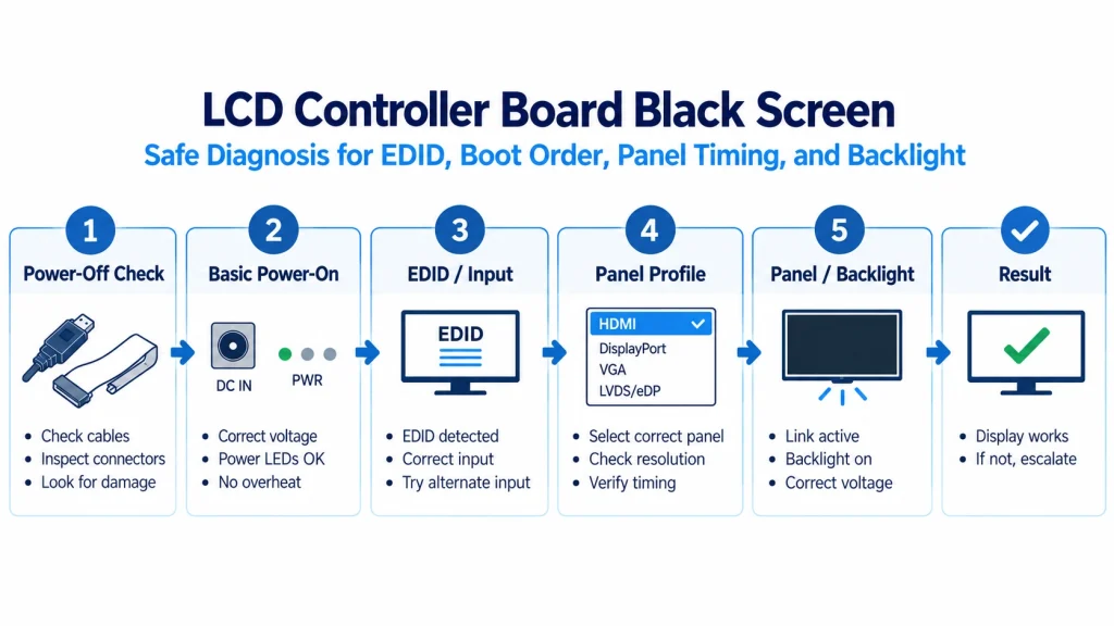
A symptom-led workflow that separates power, light, input, processing, panel link, initialization, and mapping
Safety gate — stop before testing
This flow is for trained technicians working on low-voltage display systems with exact documentation. LED backlight boost outputs and mains-powered equipment can be hazardous. Do not hot-plug unsupported panel connectors, short pins, change protection components, or probe high-speed/floating/boost nodes with unsuitable instruments.
Quick answer
A black LCD does not identify one failed part. First make the setup safe and freeze its configuration. Then separate no power, no backlight, no accepted input, bad EDID or source mode, wrong controller firmware/profile, incorrect panel timing or LVDS/eDP mapping, missing panel initialization, cable/contact failure, boot-order sensitivity, and environmental intermittence. Use low-risk observations and documented status before electrical probing.
Classify the Symptom Before You Probe
Black screen is an appearance, not a diagnosis. The display may be completely unpowered, the LCD cell may be active with no light, the backlight may be on with black pixel data, the source may be absent, the controller may not lock, the panel link may be misconfigured, or the image may be outside the visible active area. More than one fault can coexist after a board or panel substitution.
Begin by identifying the exact known-good configuration: source and mode, controller-board part and revision, firmware or panel profile, EDID, panel part and revision, LVDS/eDP cable, backlight cable, touch cable, key board, power supply, dimming setting, and boot order. Photograph connector orientation and labels with power removed. A troubleshooting result is not reusable if the configuration changes between steps.
Separate light from image without declaring a cause. Observe whether the backlight visibly illuminates, whether brightness control changes it, and whether the controller indicates a backlight fault. A faint-image inspection may be useful on some transmissive LCDs when performed safely, but it is not conclusive and does not apply to emissive OLED. Never disassemble an energized backlight or probe its boosted output casually.
On the source side, confirm that the source detects a display, what mode and format it selected, and whether a known-good monitor or capture path confirms output. Read the controller’s EDID where supported and archive the bytes. A valid EDID shows that one low-speed information path responded; it does not prove the receiver locked the video or the panel output is correct.
Trace the custom TFT controller signal chain from the source-facing input through the controller and bridge functions to the panel-side link. Naming each boundary prevents a source handshake symptom from being mistaken for a failed panel or backlight.
On the panel side, verify firmware/profile identity before changing settings. The board must generate the exact native timing, interface configuration, mapping, bit depth, power sequence, and backlight behavior required by the panel. Loading a similar profile or swapping cables experimentally can create new faults or damage. Escalate when the exact configuration is unavailable.
A useful baseline is not a shopping list of headline specifications. It is a controlled comparison record in which every requirement has a source, a unit, a tolerance or condition, and an owner. Mark each entry as mandatory, preferred, negotiable, unknown, or not applicable. Unknown values should become questions or sample tests; they should never be silently copied from a similar part.
Use the following matrix as a working gate. The entries describe what the project team must verify, not universal pass values. An approved result should point to the exact drawing, datasheet revision, configuration file, inspection record, or measurement report that supports it.
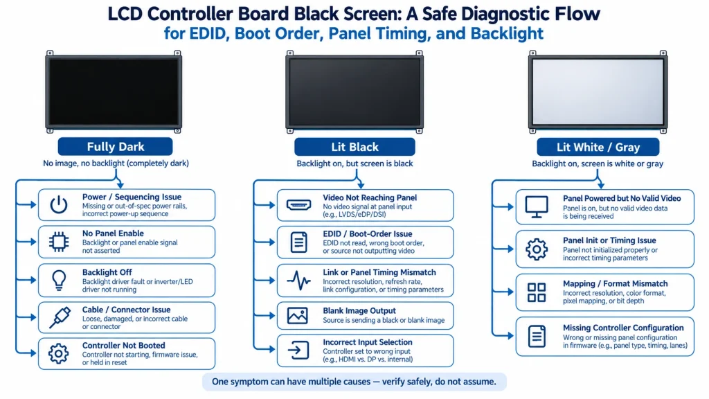
Phase 0 — Freeze the Test Configuration
Run the work in a fixed order so that inexpensive document mismatches are found before hardware is modified or samples are committed. Keep the original configuration available as a reference until the new path has passed the same acceptance tests. A step may be repeated after new evidence arrives, but it should not be skipped merely because the display produces an image once.
- Make the equipment safe, disconnect unsupported hot-plug paths, apply ESD controls, and obtain the exact board, panel, and power documents.
- Freeze and record source, mode, board/revision, firmware/profile, EDID, panel, cables, settings, supply, enclosure state, and symptom timing.
- Inspect with power removed for reversed or partial connectors, latch damage, FPC contact side, cable strain, contamination, corrosion, and visible damage.
Freeze the approved state as a package: full orderable part number, suffix, drawing, datasheet, connector and cable drawing, firmware or register configuration, host software version, optical stack, touch stack, backlight settings, mechanical stack, acceptance limits, and photographs of markings. Store hashes for binary files and identify which files are supplier-controlled versus customer-controlled.
A golden sample is useful only when it is linked to written limits and protected from uncontrolled use. It can show a visual or mechanical reference, but it cannot reveal hidden firmware, material, or process changes. Keep at least one approved unit, its lot identity, and the measurements that made it acceptable. Use written specifications for repeatable production decisions.
When a deviation is proposed, classify it before deciding the depth of review. A connector-vendor change may be mostly mechanical and reliability-related; a timing-controller revision may affect initialization, color, power, or boot order; an optical film change may affect brightness and uniformity without changing the electrical drawing. The classification determines the regression plan, not the supplier’s description of the change as minor.
Phase 1 — Separate Board Power from Backlight State
- Verify the documented low-voltage input supply, polarity, board indicators, current behavior, and configured panel/backlight output without probing hazardous nodes.
- Separate backlight and pixel-path symptoms; confirm brightness/enable settings and whether the panel shows any controlled test pattern.
Interpret power and light as separate gates. Stable board input does not prove that the panel logic rail, backlight driver, enable, dimming command, or LED load is correct. Conversely, visible illumination does not prove that valid pixel data reaches the panel. Use documented low-voltage status and safe observations before any qualified measurement.
Phase 2 — Prove Source Detection, EDID, and Input Lock
- Validate the source using a known-good display, then check controller detection, EDID, selected timing/format, input lock, and error/status logs where supported.
Use the earliest failed gate to narrow the next test, not to declare a failed component. If the board has no stable input power, later EDID or panel checks are not meaningful. If EDID is readable but the receiver never locks the selected mode, investigate source timing, cable, receiver limits, firmware, and format. If input locks but the panel path fails, focus on profile, output, power, sequence, cable, and panel requirements.
Use o industrial display interface selection guide to distinguish HDMI or DisplayPort source negotiation from LVDS or eDP panel delivery. A connector name alone does not establish direction, protocol role, accepted timing, mapping, or bridge behavior.
EDID symptoms can be subtle. A source may cache old information, select a non-native mode, reject a corrupt checksum, or behave differently across operating systems and boot orders. Record raw EDID and source-reported mode. Restore only the approved vendor file or a controlled override. Do not invent blocks or advertise modes the board cannot process and the panel cannot display.
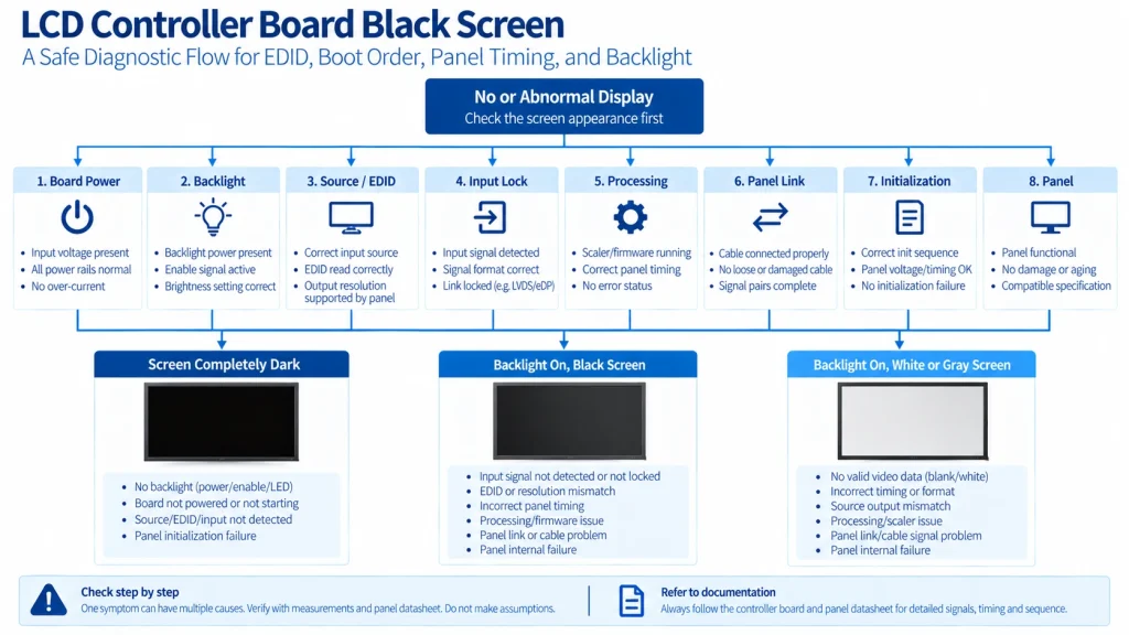
Phase 3 — Verify the Panel Output, Profile, and Initialization
- Confirm exact firmware/profile, native panel timing, output interface, lane/channel mapping, cable, panel power sequence, and initialization.
Wrong or absent panel timing can resemble a dead panel. Confirm complete totals, porches, sync/DE mode, polarity, pixel clock, refresh tolerance, LVDS mapping or eDP link, color depth, and output format from controlled documents. A resolution label does not define these values. Do not sweep clocks or load unrelated profiles into production hardware without panel and controller limits.
If the symptom is flicker, intermittent color, or unstable LVDS rather than a consistently black state, branch to the LVDS flicker diagnostic guide. Do not collapse those symptoms into this no-image path or assume that the same corrective action applies.
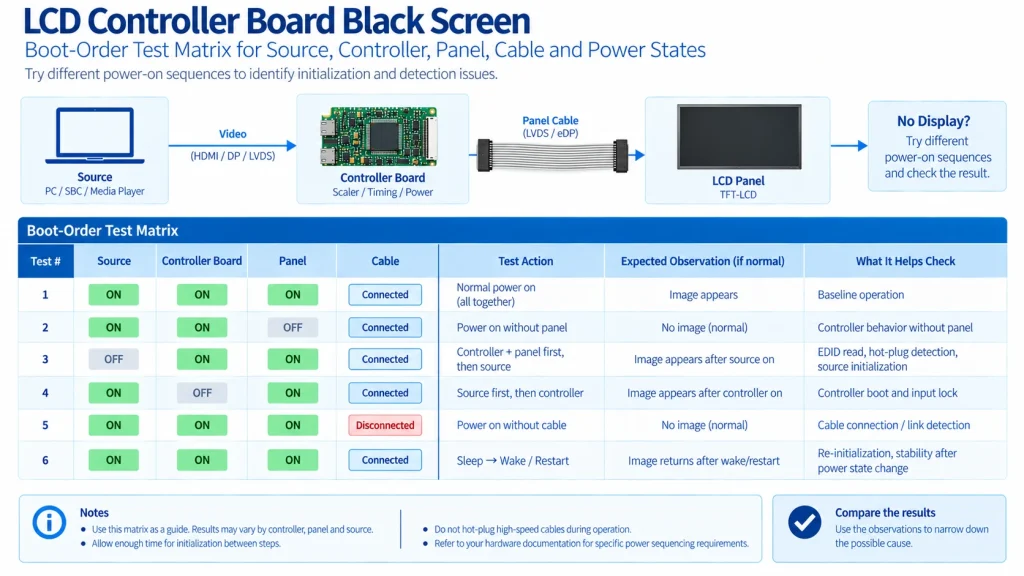
Phase 4 — Reproduce Boot-Order and Intermittent States
- Run a controlled boot-order, sleep/wake, mode, temperature, and cable-position matrix; escalate with captured evidence before component-level changes.
Boot-order sensitivity is valuable evidence. Build a matrix for source off/on, controller off/on, panel power cycle where supported, cable present/absent at startup, sleep/wake, restart, and brownout recovery. Record time and state indicators. The goal is to locate HPD/DDC/EDID timing, receiver lock, reset, firmware, panel sequence, or backlight dependencies, not to institutionalize a fragile ritual as the fix.
Keep known-good controls honest. A spare board, panel, cable, or power supply is useful only when its identity and compatibility are verified. Label controls, protect them from casual production use, and periodically retest them. A control that has unknown firmware or a different panel profile can falsely implicate a healthy component or conceal the original problem.
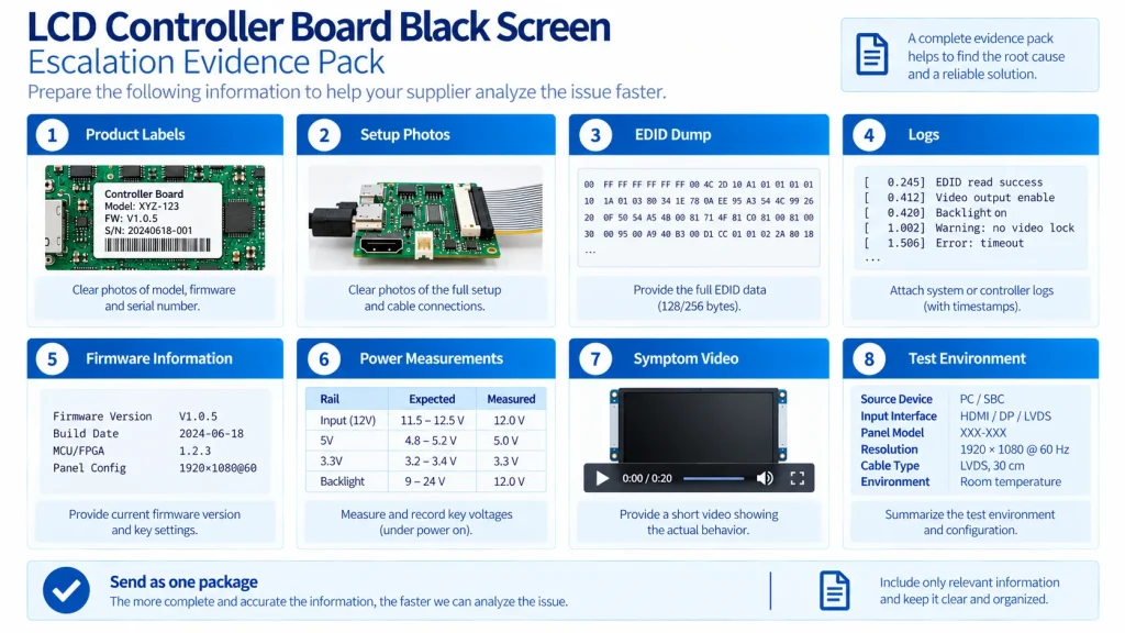
Interpret Evidence and Prepare Escalation
Escalate when safe evidence is exhausted. Provide symptom video, configuration photos, full part/revision labels, EDID dump, source modes, firmware/profile, power-cycle matrix, controller logs/status, environmental conditions, and changes from known good. This package lets the board or display supplier reproduce the state and reduces pressure for risky trial-and-error repair.
Send questions with the exact project configuration attached. Ask for document numbers and revision dates rather than a simple yes or no. Where the answer depends on a sample, ask the supplier to state the proposed test method and which party owns approval. This turns a sales exchange into a traceable engineering handoff.
- What exact board revision, firmware/panel profile, EDID, cable, panel revision, key board, and power supply form the approved set?
- What indicators, logs, status registers, test patterns, and recovery functions are supported and documented?
- Which source modes and formats are accepted, and which EDID bytes should the approved configuration expose?
- What panel native timing, LVDS/eDP configuration, mapping, power sequence, initialization, and backlight control are required?
- Which connectors are safe to mate only when powered off, and what ESD or service procedure applies?
- Are LED backlight outputs isolated or boosted, and what qualified measurement method and test points exist?
- What boot-order, hot-plug, sleep/wake, brownout, and temperature states were validated by the supplier?
- What evidence should be returned for RMA, and which settings or seals must not be altered before analysis?
Verify the Fix Before Closing the Issue
Validation should reproduce the states that matter in the finished equipment: cold start, warm restart, brownout recovery, representative content, brightness extremes, touch operation, expected cable routing, enclosure loading, and the intended software image. Separate engineering verification from supplier outgoing inspection. Both are useful, but they answer different questions.
Define pass criteria before testing. Record sample identity, lot, revision, firmware, test equipment, environmental condition, configuration, and raw observations. A result such as ‘looks good’ is not reusable evidence. A result tied to a controlled pattern, measurement setup, limit, and reviewer can support release and later change analysis.
After recovery, perform a fix-verification matrix. Reproduce the original failure condition, apply the controlled correction, repeat cold and warm starts, required modes, dimming, touch, sleep/wake, cable routing, temperature points, and production programming. Record negative tests where practical. Closing the issue after one successful reboot invites recurrence.
Unsafe Shortcuts and False Conclusions
Most late failures come from an unsupported inference: one matching attribute is treated as proof that the whole signal, mechanical, optical, or lifecycle path is equivalent. The corrections below deliberately replace certainty with the next piece of evidence the team should collect.
- Backlight illumination does not prove the LCD pixel data, timing, mapping, or initialization path is correct.
- A readable EDID does not prove the input receiver is locked or the panel link is active.
- A faint image or one current reading cannot uniquely identify backlight, panel, controller, cable, or firmware failure.
- Swapping similar panel cables can short rails or misroute signals even when the connectors fit.
- Random firmware or panel profiles can create damage, corrupted settings, or a misleading second fault.
- Probing LED boost or high-speed differential lanes with unsuitable equipment can be hazardous or invalidate the measurement.
Perguntas Frequentemente Fazidas
Why is the LCD backlight on but there is no image?
Possible paths include black source content, no input lock, wrong firmware/profile, incorrect native timing, LVDS/eDP configuration or mapping, missing panel initialization, panel logic power or sequence, cable/contact failure, or a panel fault. Confirm source mode, controller status, exact configuration, test pattern, cable, power, and panel requirements before assigning a cause.
Can a bad EDID cause an LCD controller board black screen?
Yes, it can cause the source to see no display or select an unsupported mode, but EDID is only the source-facing description path. Even a valid EDID does not prove receiver lock, scaling, panel timing, output link, power sequence, backlight, or initialization. Archive the raw EDID and compare it with the approved configuration.
Why does the display work only when devices power on in a certain order?
The behavior can indicate timing dependencies involving HPD, DDC/EDID, source mode selection, receiver lock, reset, firmware initialization, panel power sequence, or backlight enable. Reproduce it with a controlled state matrix and logs. The durable fix should address the documented dependency rather than relying on a manual startup ritual.
Is it safe to swap an LVDS or eDP cable during troubleshooting?
Do not hot-plug unless every involved product explicitly supports it. With power removed, a cable should still be used only after its pinout, contact orientation, connector, mapping, current paths, shielding, and panel/board compatibility are verified. Similar connectors can route power and signals differently and may damage the equipment.
Close the Engineering Handoff
Diagnose a controller-board black screen as a sequence of states. Make the setup safe, freeze its identity, separate power, backlight, source discovery, input lock, processing, panel link, initialization, mapping, and boot order, then collect controlled evidence. Avoid random cables, firmware, clock sweeps, and hazardous probing. Release a fix only after the original symptom and required recovery matrix pass.
If the controlled evidence still does not isolate the failed gate, contact KadiDisplay engineering with the board and panel revisions, firmware or profile ID, EDID dump, source modes, cable identity, photos, logs, boot matrix, environmental state, and symptom video. Exact indicators, test points, recovery procedures, backlight topology, and RMA requirements must be confirmed for the specific board-and-panel set.
Primary Sources and Technical References
Confirm each source revision and the exact supplier documents for the production configuration; these references do not create universal supplier terms.
Engineering disclaimer
This article is a verification framework, not a substitute for the exact panel, controller, bridge, connector, power, mechanical, software, supplier, and compliance documentation used in a production design. Confirm the full part number and revision, use appropriate ESD and measurement practices, and validate the final system under its real mission profile before release.
PRIVENTE
LCD Prototype Passed but Pilot Units Fail: A Display Integration Isolation Workflow
NEXTO
VESA vs JEIDA LVDS Mapping: Evidence-Based Color Diagnosis and Release
Deixe um comentário

Recent Blog & News
- MIPI DSI Display Works at Room Temperature but Fails After Warm-Up: A Troubleshooting Workflow
- LCD Prototype Passed but Pilot Units Fail: A Display Integration Isolation Workflow
- LCD Controller Board Black Screen: A Safe Diagnostic Flow for EDID, Boot Order, Panel Timing, and Backlight
- VESA vs JEIDA LVDS Mapping: Evidence-Based Color Diagnosis and Release
- eDP LCD Panel Integration: Power, AUX, Link Training, Video and Backlight

