




الصفحة الرئيسية
-
مدونة & أخبار
-
Common ZIF Connector Problems in Industrial Touchscreens and How to Fix Them
Common ZIF Connector Problems in Industrial Touchscreens and How to Fix Them
2026-07-28
16:33
Common ZIF Connector Problems in Industrial Touchscreens and How to Fix Them
A symptom-led troubleshooting guide for touch failure, garbled image, white screen, backlight out, and intermittent contact — organized to distinguish ZIF connector root causes from the electrical and firmware problems they’re most often confused with
Why ZIF Connector Problems Look Like Software Problems
The most telling sign of a ZIF connector failure in an industrial touchscreen is not the connector — it’s the symptom. A half-inserted LCD ribbon cable doesn’t announce itself as a mechanical problem. It announces itself as a white screen, a garbled image, a touch that stopped responding, or a backlight that won’t come on. Every one of those symptoms also has a software, firmware, or electrical explanation, which is exactly why a team will spend hours in device tree overlays, touch driver code, and backlight PWM settings before someone finally touches the FPC cable and everything starts working again.
This pattern repeats so consistently in industrial display field service — and in embedded display bring-up — that it has its own informal diagnosis rule: before deep-diving into firmware for any display symptom that appeared after a physical handling event (installation, cable re-routing, enclosure closure, shipping), check the connectors first. The rule saves more debugging time than any single firmware technique.
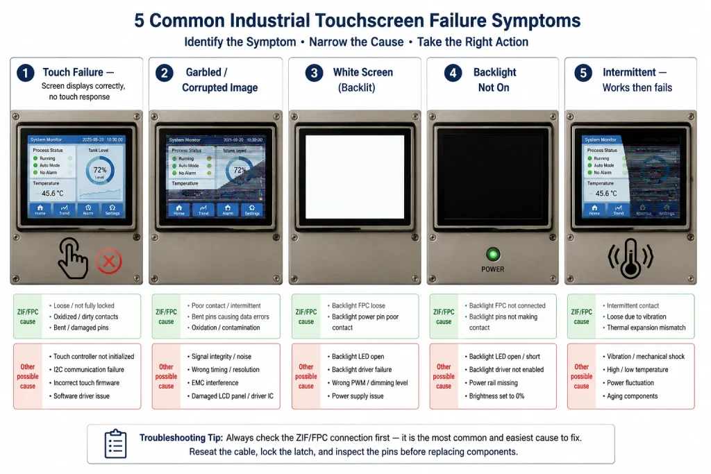
This guide is organized around the five specific symptoms most frequently caused by ZIF and FPC connector problems: touch failure, garbled or corrupted image, white screen, backlight failure, and intermittent contact that appears and disappears correlated with temperature or vibration. For each symptom, the guide explains how to identify when the connector is the cause versus when something else is responsible — because misidentifying connector problems as electrical problems wastes time, and misidentifying electrical problems as connector problems can damage a working display during unnecessary reseating attempts.
How ZIF Connectors Work — and the Two Ways They Most Commonly Fail
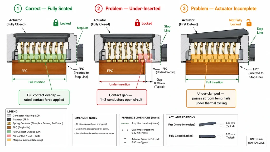
A ZIF (zero insertion force) connector accepts an FPC (flexible printed circuit) ribbon cable by opening a hinged or sliding actuator, receiving the cable with essentially no resistance, then clamping the cable firmly against a row of spring contacts when the actuator is closed. In theory, this is a reliable mechanism that protects both the cable and the contacts from damage during repeated insertion. In practice, two failure patterns account for the vast majority of field problems.
The first is under-insertion: the cable is physically inside the connector body but hasn’t traveled the full distance to the contact zone. At 0.5mm pitch (the most common pitch in industrial touch display cables), the conductor pads are only 0.25mm wide with roughly 0.2mm of contact overlap. A cable that’s 0.3mm short of full insertion — less than a third of a millimeter — may leave one or two conductors outside the contact zone. That’s enough to interrupt a data lane, a power rail, or a touch I²C line. The symptom looks like an electrical failure because it is one: the circuit is genuinely open. The fix is purely mechanical.
The second is actuator not fully closed: the cable is fully inserted but the locking actuator was closed only to its first detent rather than its final position. Many ZIF actuators have a two-stage closure — a soft stop that feels complete but leaves contact force below rated value, and a firm final close that applies the specified 0.3–1.0 N per contact depending on connector grade. An actuator in the first-stage position may pass initial testing at room temperature, then lose contact when the panel heats up by 20°C and the slightly different thermal expansion of cable and connector body shifts their relative positions by the fraction of a millimeter that the under-clamped spring contacts cannot compensate.
Symptom: Touch Not Responding — Screen Displays Correctly
A touchscreen that displays a correct, stable image while completely ignoring all touch input is one of the most common presentations of a touch FPC connector problem. The display’s data path (LCD cable, LVDS, MIPI DSI, or RGB parallel) is unaffected, meaning everything about the image is normal, but the capacitive touch controller’s I²C communication lines (SDA, SCL), power supply pins (VDD, GND), or control signals (INT, RST) are broken at the connector.
S-01 Touch Failure — Display Normal
When ZIF/FPC is the cause: GT911 or other capacitive touch controller is not responding on I²C — bus scan returns nothing at 0x5D or 0x14. SDA, SCL, VDD, or GND conductor on the touch FPC is open at the connector. Typical cause: touch module on a separate FPC connector from the display, and that connector wasn’t fully seated after installation.
Clues pointing away from connector: Touch failure present from initial bring-up with no physical disturbance; I²C bus wiring confirmed correct; firmware issue (wrong address, timing bug); GT911 VDD absent from power supply design.
- Connector fix: Run an I²C bus scan and confirm whether the touch controller appears at either 0x5D or 0x14. If it appears at neither address: Open and reseat the touch FPC connector. The touch module often uses a separate, smaller ZIF connector near the display module’s edge — not the main display data connector. Confirm the actuator closes fully to its final position, not just its first detent.
- Mark the insertion depth on the cable with a permanent marker before reseating, so the mark’s position relative to the connector body edge confirms full insertion after the actuator is closed.
- After reseating, re-run I²C bus scan before powering on the full system — a working touch controller should appear within milliseconds of power application.
One important clarification for GT911-based touch panels: a GT911 that was previously detected at 0x5D but now appears at 0x14 (or vice versa) is not a connector open-circuit problem — it’s an INT pin state change during reset, typically caused by the INT conductor being marginal rather than fully open. Marginal contact on the INT pin lets it float during the reset sequence rather than being held at the level the firmware drives it to, causing the address latch to sample a floating level that happens to register as the opposite level. The distinction matters because this symptom sometimes appears after reseating a connector that was only slightly under-inserted, and it can be confused for a firmware reset-sequence bug.
Symptom: Garbled, Corrupted, or Banded Image
A garbled image — horizontal bands, vertical color stripes, checkerboard noise, diagonal tearing, or a correct image over part of the screen with corruption elsewhere — is the symptom most directly tied to a partial connection on the display data path rather than the touch path. The specific corruption pattern often encodes which data lines are affected, making garbled image cases one of the more tractable connector symptoms to diagnose if you know the mapping.
S-02 Garbled or Banded Image
When ZIF/FPC is the cause: One or more display data conductors on the main FPC ribbon cable are making marginal or intermittent contact. For RGB parallel displays, each data lane carries 1-2 bits of color depth per channel — a single open lane shifts the affected color channel’s value by a fixed bit, producing characteristic color banding. For MIPI DSI or LVDS, a lane failure produces much more severe corruption because differential data streams require both conductors.
Clues pointing away from connector: Corruption present from first power-on with confirmed correct firmware/device tree; corruption pattern doesn’t change with cable movement or pressure; corruption matches known driver IC bug pattern.
- Connector fix: Identify the corruption pattern: uniform horizontal same-color bands suggest a specific color bit error (RGB data line fault). Severe random noise over full screen suggests a differential pair fault (LVDS/MIPI). Partial screen correct + rest corrupted suggests a data enable (DE) or sync signal fault.
- Gently flex the FPC cable while the display is powered on (with care). If the corruption changes or disappears during flexing, the cable or connector is the cause. If no change, the problem is elsewhere.
- Reseat the main display FPC connector and observe whether the corruption pattern changes. A different pattern after reseating confirms mechanical cause even if not fully resolved.
- Check cable routing for sharp bends — a crease in the cable produces conductor fractures that behave identically to a contact failure.
Symptom: White Screen — Backlight On, No Image Content
A uniformly bright white screen with no image content, where the backlight is clearly lit, is one of the ZIF connector symptoms most often misdiagnosed as a software problem. The engineer sees the backlight working and concludes power delivery is fine, then spends hours investigating device tree overlays, display driver configuration, and video signal timing before discovering that the display data cable wasn’t properly seated.
S-03 White Screen — Backlight Present, No Image
When ZIF/FPC is the cause: The display panel’s LCD data path is not receiving valid video data from the host, but the backlight driver is operating independently of the data path and remains lit. In this state, the LCD panel defaults to its un-driven state, which for most IPS panels is a white (fully transmissive) appearance. The FPC ribbon cable carrying the pixel data (RGB parallel bus, LVDS, or MIPI DSI) is partially inserted or the actuator is not fully closed.
Clues pointing away from connector: White screen with no prior physical disturbance; confirmed device tree or video driver issue; display worked previously without touching cables; MIPI DSI lane negotiation failure visible in dmesg output.
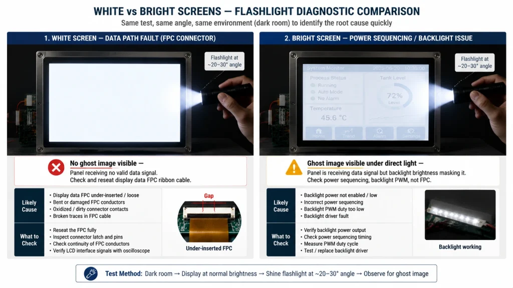
- Connector fix: First: confirm the symptom pattern: shine a bright flashlight at the panel surface from an extreme angle. If you see a faint ghost of the expected UI content, the panel’s backlight is too bright relative to the panel’s own light output (power sequencing issue). If the screen is purely white with no ghost image visible, the display data path is genuinely receiving no signal or incorrect signal.
- Reseat the display data FPC with the system powered off. This is the main ribbon cable connecting to the host board’s LCD/display interface, not the touch cable. After reseating, verify the actuator is firmly in its final locked position, not intermediate.
- Check the insertion depth mark as described in Section 2 — for white screen cases specifically, under-insertion of even 0.5mm on an 800×480 RGB panel can drop enough data lines to produce all-white output while keeping the backlight completely unaffected.
Symptom: Backlight Not On — Screen Completely Dark
A completely dark panel where no light is detectable even under a strong flashlight in a dark room is a harder connector diagnosis than the other symptoms, because the backlight circuit is usually a more robust, higher-current path than display data or touch I²C signals. In some display module designs, the backlight power connections share the same FPC cable as display data; in others, they’re on a separate, dedicated connector. Understanding which design your panel uses is the first diagnostic step.
S-04 Backlight Failure — Screen Completely Dark
When ZIF/FPC is the cause: The backlight LED string’s power or enable signal is interrupted at a connector. In modules where backlight and data share one FPC cable, severe under-insertion can interrupt the backlight power pins before impacting data lines (since power is often routed on outer pins). In modules with a separate backlight connector, that connector is the first thing to check.
Clues pointing away from connector: Dark screen present immediately with no prior handling; confirmed no backlight driver power supply; backlight driver IC thermal shutdown from overcurrent (check for heat); backlight enable GPIO not driven by host firmware.
- Connector fix: First: identify whether the panel uses a combined or separate backlight connector — check the module’s datasheet or FPC pinout. If separate, inspect and reseat the backlight connector specifically.
- Measure the backlight enable signal at the host PCB output pin. If the enable signal is present and correct but the backlight doesn’t light, the problem is between the enable pin and the backlight driver — possibly an FPC conductor for the backlight enable line.
- For combined cables: with system powered off, use a multimeter in continuity mode to check the backlight supply pins (VLED+, VLED−, or similar labeling) through the FPC to the display module connector. Open circuit on either confirms a connector or cable fault.
Symptom: Intermittent Failure — Correlated with Temperature or Vibration
Intermittent display or touch failures that appear and disappear in correlation with temperature changes, vibration events, or specific handling are the most difficult connector problems to diagnose because they’re invisible during inspection. The connector looks perfectly seated, the cable shows no obvious damage, and the system works perfectly during bench testing — then fails after installation, or after reaching operating temperature, or after road transport.
S-05 Intermittent Failure — Appears and Disappears
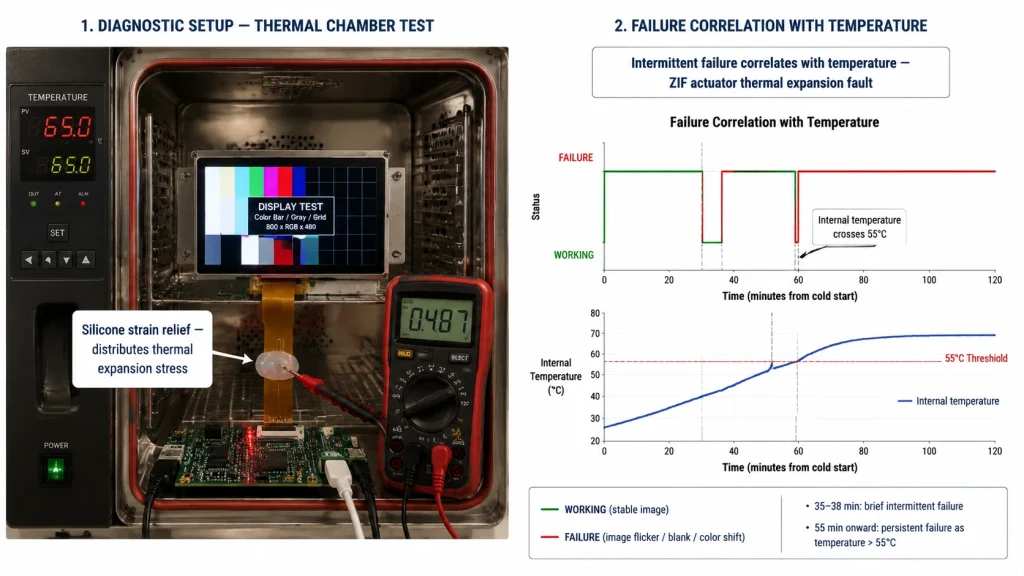
When ZIF/FPC is the cause: Actuator not at final lock position (first-detent false closure) — thermal expansion of connector housing shifts relative to cable conductor pads; CTE mismatch between polyimide FPC (~20 ppm/°C) and FR4 PCB (~17 ppm/°C) progressively works the cable backward; FPC cable crease causing a marginal fracture that opens and closes with bending.
Clues pointing away from connector: Failure appears randomly without temperature or vibration correlation; failure appears immediately and is constant from first power-on; failure resolves permanently after a single reseat without any other change.
- Connector fix: Log failure timestamps relative to operating temperature — even a rough correlation (“happens after 30 minutes of operation”) narrows the search significantly toward thermal expansion causes.
- Inspect the cable routing for any sharp bends or points where the cable is squeezed or strained by enclosure closure — these locations fatigue the copper traces over time and produce intermittent failures that worsen progressively.
- Apply silicone strain relief bead (Shore A 30-40) at the FPC cable exit from the ZIF connector housing — this distributes thermal expansion strain over a gentle bend radius rather than concentrating it at the connector edge.
- Verify actuator final position with a loupe or macro photograph — the actuator top surface should be flush with the connector body with no visible gap at either end when fully closed.
Prevention — What Happens at Assembly Determines What Happens in the Field
ZIF connector problems in industrial touchscreens are almost never random events — they’re overwhelmingly the result of a specific assembly step that wasn’t performed correctly, then scaled to whatever production volume shipped before the problem surfaced. Prevention is far cheaper than field service, and it concentrates in three places: assembly procedure, visual inspection, and production test.
- Write and enforce an explicit assembly procedure for every ZIF connector in the product. “Insert FPC cable and close connector” is not a procedure — it’s a description. A procedure specifies: open actuator fully, confirm FPC has the insertion depth mark, align cable straight to connector axis, insert until depth mark is at connector body edge, close actuator to audible/tactile final click, apply strain relief where specified. Operators who have been shown the procedure once and observed performing it correctly are significantly more consistent than operators relying on intuition alone.
- Mark every FPC cable with an insertion depth line. This practice, mentioned in Kadi Display’s guide on ZIF connectors in industrial LCD displays, is one of the simplest and most effective manufacturing controls available. A line drawn perpendicular to the cable at the correct insertion depth should sit flush with the connector body edge after closing — visible in a five-second visual check.
- Include connector inspection in the end-of-line test sequence. A display functional test that verifies the backlight, image quality, and touch response at room temperature catches the majority of ZIF insertion failures before shipment, since most under-insertion problems are consistent from the first power-on, not intermittent. Adding a brief thermal soak (15–20 minutes at 10°C above expected maximum operating temperature) before the final test catches actuator-not-fully-closed failures that only manifest under heat.
- Apply strain relief to every FPC connector in a vibration or thermal cycling application. A silicone bead at the cable exit from the connector is a standard assembly step in automotive and industrial display production specifically because it addresses the thermal-cycling failure mode at a labor cost of under 30 seconds per unit.
📌 Check Connector First — Especially After Any Physical Event
The single highest-yield change in industrial display troubleshooting workflow: before investigating firmware, drivers, or power supply for any display symptom that appeared after a physical event — installation, shipping, enclosure closure, cable rerouting — fully open and reseat every FPC ribbon connector in the assembly. This takes under five minutes and resolves the problem in a substantial fraction of cases, avoiding hours of unnecessary firmware investigation. For a deeper treatment of failure mode patterns by connector type, Kadi Display’s article on LCD display connector failure modes covers ZIF lock failures, cable fatigue, solder joint issues, and contact wear across the common industrial touchscreen connector types.
Quick Reference — Symptom to Connector Check to Resolution
مرجع المنتج والدعم الهندسي
For industrial TFT-LCD and touch display modules with fully documented FPC pinout, correct ZIF connector specifications for production assembly, and technical support for field connector failure diagnostics, contact Kadi Display at Sales@sz-kadi.com. Browse industrial touchscreen repair and integration guides →
تنصل: Diagnostic procedures, connector specifications, and troubleshooting steps in this guide are general engineering reference information and must be verified against your specific display module datasheet, FPC pinout documentation, and host platform characteristics. Actual failure modes and fixes vary by module design and connector manufacturer. Always follow appropriate ESD handling precautions when working with FPC connectors and display modules. All brand and product names are the property of their respective owners.
السابق
MIPI DSI LCD Platform Selection Guide: Match the Panel to the Host
التالي
ESP32-S3 RGB Display with GT911 and LVGL: A Practical Guide for Kiosk and HMI Applications
اترك تعليق

آخر مدونة وأخبار
- MIPI DSI Display Works at Room Temperature but Fails After Warm-Up: A Troubleshooting Workflow
- How to Choose an LCD Controller Board: Architecture, EDID, Timing and Latency
- Industrial Display RFQ Checklist: Build a Supplier-Ready Evidence Package
- Industrial LCD Drop-In Replacement Checklist: From Hard Stops to Release Evidence
- MIPI DSI in Industrial LCD Displays: What Engineers Should Know
مدونة ذات صلة وأخبار
-
 TN مقابل IPS2024-7-9
 -
TN مقابل IPS2024-7-9

