




MIPI DSI and Capacitive Touch: Why the Interfaces Are Separate
2026-08-06
13:08
MIPI DSI and Capacitive Touch: Why the Interfaces Are Separate
Display pixels travel over DSI; touch coordinates usually use I²C, SPI, or USB—plus separate reset, interrupt, power, and driver responsibilities
A touch display may look like one component, but its LCD and touch controller are separate endpoints with different bandwidth, direction, timing, and software needs. This guide explains the architecture without incorrectly describing DSI as strictly one-way or assuming every touch controller behaves like GT911.
The Question Every New Display Engineer Asks
Direct answer — DSI terminates at the display controller. Touch terminates at a separate controller, normally reached through I²C, SPI, or USB. One module can expose both paths through one connector, but the electrical and software interfaces remain separate.
Related Kadi Display reference: Kadi Display’s GT911-to-LVGL integration guide.
Engineers encountering MIPI DSI touch screen modules for the first time almost universally ask the same question: why does the display panel need two separate cable connections — one for the display image and one for touch input?
The question is reasonable. In a smartphone or tablet, the display and touch appear to be a single integrated unit — tap the screen and something happens. But the electrical architecture underneath involves two completely independent communication systems operating in parallel.
This architectural separation is not a legacy compromise or a cost-saving shortcut. It exists because the electrical requirements for pushing high-speed pixel data and reading low-speed touch coordinates are fundamentally incompatible within a single interface protocol.
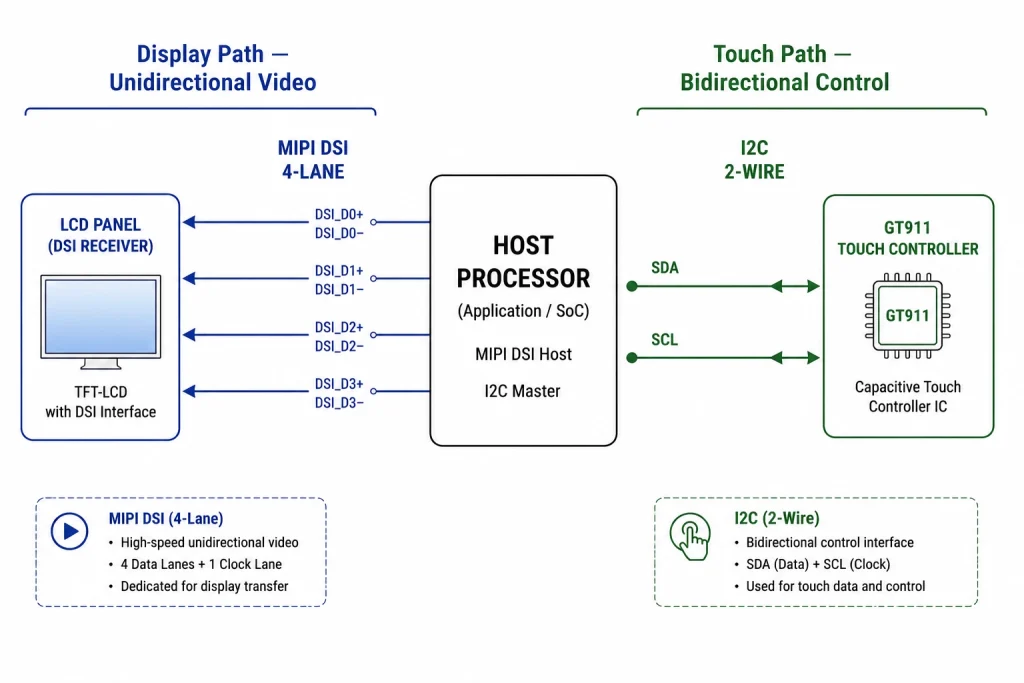
What MIPI DSI Actually Carries — And What It Cannot
Terminology correction — Do not call DSI strictly unidirectional. Conventional DSI can support bus-turnaround/read transactions on data lane 0, but that does not carry an independent touch controller’s event stream.
MIPI DSI is primarily a host-to-display interface for commands and pixel transport. Conventional DSI also supports low-power bidirectional transactions on data lane 0 through bus-turnaround mechanisms when the host and peripheral implement them. That limited readback capability does not make DSI a general-purpose bus for an independent touch controller.
The key mismatch is architectural: the display controller consumes image data and display commands, while a separate touch controller scans a sensor and reports events or coordinates. Even when both functions share one physical assembly or cable, they remain different logical endpoints and driver stacks.
What the Touch Controller Does — And Why I2C Is the Right Bus for It
A capacitive-touch controller scans the sensor matrix, filters noise, detects contacts, and reports coordinates. GT911 is one common controller, but the exact bus, addresses, report format, point count, firmware, and reset behavior belong to the module-specific controller and configuration.
GT911 modules commonly use one of two 7-bit I²C addresses, often selected by the INT/RST sequence. Implement the supplier-approved reset flow and test both documented addresses during bring-up; do not assume the same timing, pulls, or firmware image across modules.
The Noise Isolation Argument — Why Physical Separation Matters
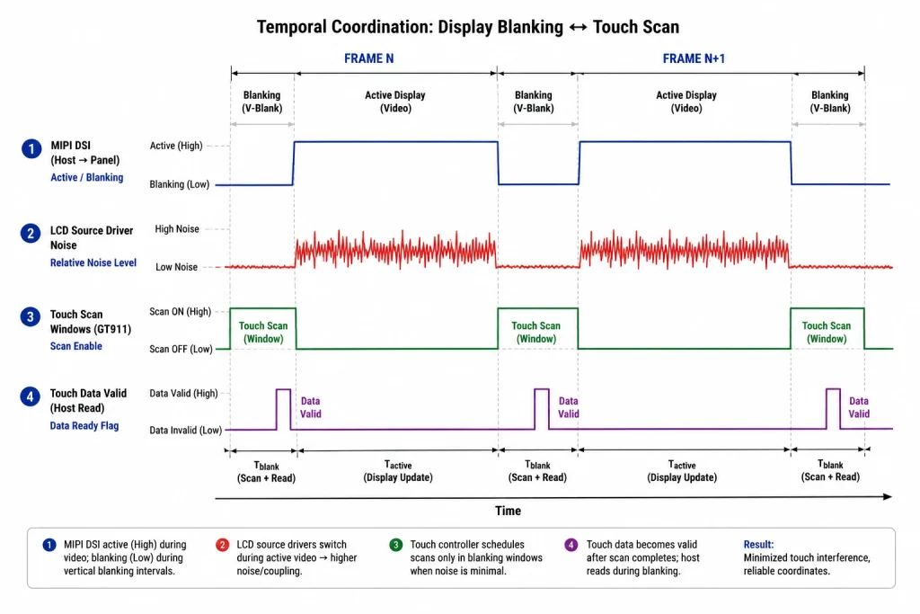
Coupling is system-specific — Do not prescribe one universal FPC spacing or scan window. Measure false-touch rate, coordinate jitter, baseline drift, and recovery while display, backlight, radios, chargers, and converters operate at worst case.
Beyond the bandwidth mismatch, there is a second compelling engineering reason for keeping display and touch interfaces physically separate: noise isolation. MIPI DSI signals switch at GHz frequencies, generating broadband electromagnetic interference that directly impacts capacitive touch sensing accuracy.
Physical separation can help, but it is not the only control. Robust touch performance may require reference conductors, power filtering, controller tuning, sensor-stack design, appropriate FPC routing, display/backlight noise testing, and firmware recovery. Scanning during blanking is implementation-specific, not a universal requirement.
Alternative Touch Interfaces — When SPI or USB Replaces I2C
While I2C is the dominant communication bus for capacitive touch controllers in industrial display modules under 15 inches, some applications require alternative interfaces for specific engineering reasons.
If the application requires SPI, USB HID, or another interface, select a controller and module that explicitly support it. Do not assume controller families share bus options; verify the exact datasheet and the firmware loaded by the module supplier.
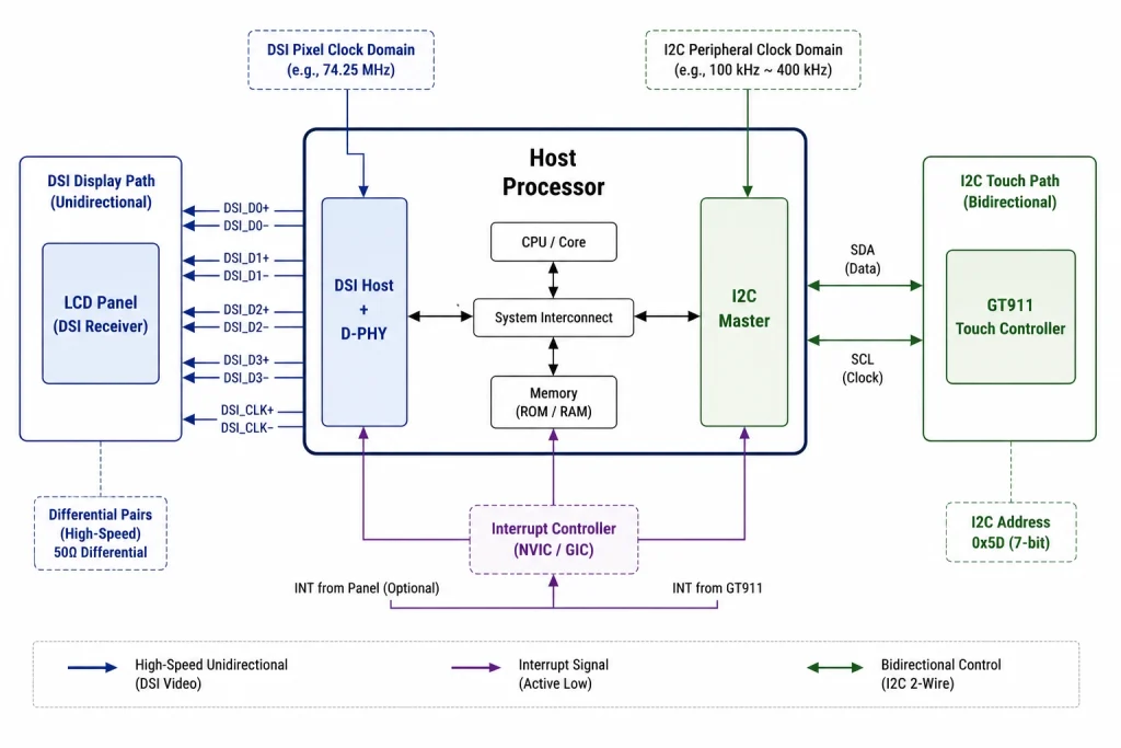
Host Processor Resource Allocation — Two Interfaces, Two Peripheral Blocks
The separation of display and touch interfaces has direct implications for host processor peripheral allocation during system design. Engineers must reserve independent hardware peripherals for each interface.
Separate interfaces improve diagnostic isolation, but the subsystems are not completely independent. They can share power, reset, grounding, connector mechanics, CPU resources, or EMI paths, so a fault in one can still disturb the other at system level.
Integration Checklist — Verifying Both Interfaces Work Independently
Related Kadi Display reference: Kadi Display’s GT911 troubleshooting guide.
Integration rule — Bring up display and touch independently, then validate them concurrently. Save separate logs so a DSI error, I²C fault, reset interaction, or noise event can be distinguished.
Given that display and touch are architecturally independent, the correct bring-up strategy is to verify each interface separately before expecting the integrated system to work.
Display and touch can be developed independently when resources allow, but the final validation must run both together under worst-case graphics, backlight, radio, charger, and environmental activity.
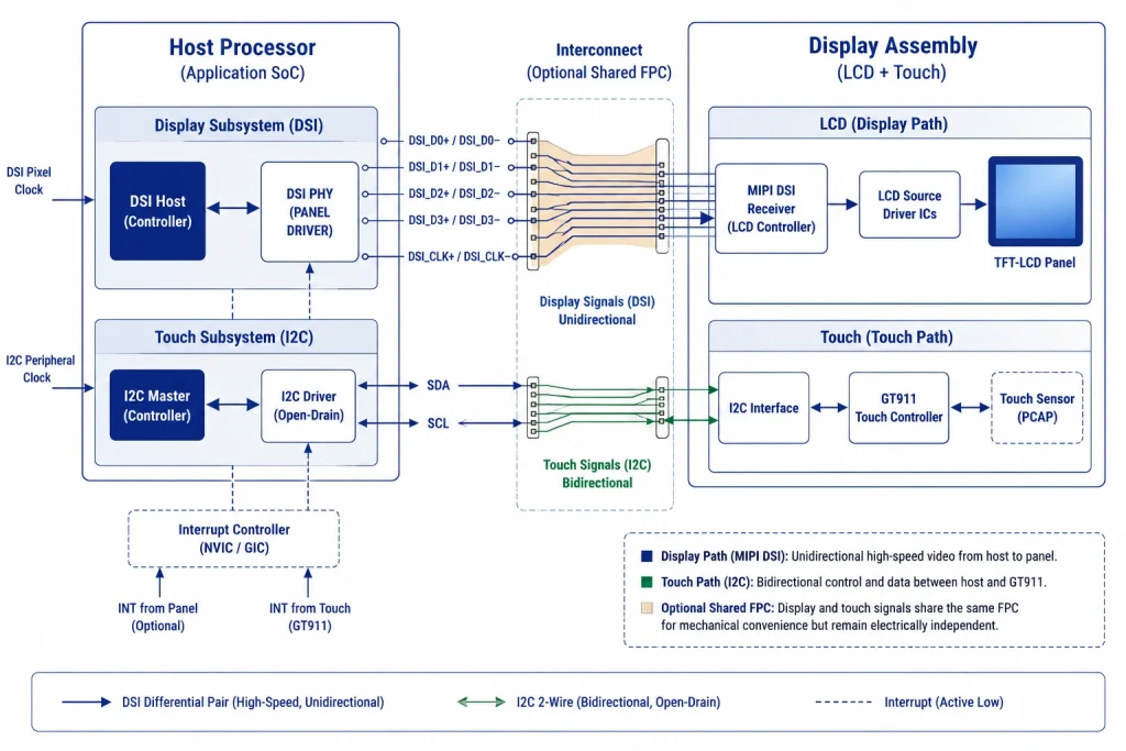
Some commercial display assemblies carry display, touch, and power through one physical FPC. That packaging choice does not merge the protocols. The host schematic still needs separate DSI and touch-controller endpoints, and the cable pinout must preserve both high-speed return paths and touch/noise requirements.
At software level, the panel driver, graphics compositor or LVGL display port, touch-controller driver, and input-device mapping should have explicit ownership. A rotation change is a good example: the display may rotate in the graphics pipeline while touch coordinates require a separate transform.
For 24/7 equipment, implement observable recovery. Count I²C timeouts, DSI host errors, panel resets, touch resets, and bus-recovery events. A self-recovered fault still belongs in the reliability data.
The power tree often creates the first hidden dependency. The LCD logic, D-PHY I/O, touch controller, backlight driver, and sensor analog section may use different rails or sequences even when the module exposes one connector. Verify which rails are internal, which are external, and whether a host reset leaves either controller partially powered through signal pins.
Reset nets deserve special attention. Some modules share a reset conductor, while others expose independent LCD and touch resets. If firmware resets the panel after the touch address has been selected, the touch controller may also restart or lose configuration. Scope both reset nodes and preserve the ordering in the production driver.
Interrupt design is touch-specific. Confirm active level, pulse or level behavior, pull direction, and whether the INT pin also participates in address selection. The driver should clear the controller’s status correctly and handle a missed edge without permanently losing input. Polling can be a useful diagnostic even if interrupts are used in production.
Coordinate mapping belongs to integration, not only the touch driver. The raw sensor coordinate space can differ from the displayed active area, especially with rotated panels, mirrored mounting, bezel dead zones, or a touch sensor shared across display variants. Store the transform and calibration evidence with the mechanical drawing.
Noise tests should use deliberate display aggressors. Alternate full white and black, high-contrast checkerboards, rapid color changes, maximum backlight duty, dimming transitions, and converter load steps while logging raw touch data. A quiet settings screen may hide coupling that appears during animation or charger operation.
I²C robustness is an electrical and software problem. Check pull-ups against bus capacitance and voltage, rise time at the controller, connector/FPC continuity, clock stretching behavior if used, timeout handling, and bus recovery. Lowering the bus frequency can diagnose margin but should not conceal a poor physical connection.
A combined connector still needs pin-group review. Place DSI pairs and their returns according to the channel design, keep noisy backlight conductors from sensitive touch paths where possible, and verify ESD discharge paths from the user-facing glass. Do not route a touch interrupt or reset through a pin that can be disturbed by the DSI return current.
System validation should include fault injection. Disconnect or disturb the touch bus without crashing the display path; force a panel reset without leaving touch coordinates stale; reboot the host with a finger on the glass; and recover from a brief rail dip. The product should return to a defined visual and input state.
Evidence Package and Release Control
Before releasing a display and touch interface architecture design, convert the article’s guidance into a requirements matrix. Give every requirement an owner, source, revision, unit, tolerance, verification method, sample quantity, and acceptance rule. This prevents an informative article from being mistaken for a product specification and makes unanswered questions visible while changes are still inexpensive.
Separate documented limits from planning assumptions. A datasheet value, vendor application note, calculated estimate, measured prototype result, and internal design target do not have the same authority. Label each one. When a value is only representative, record the condition that would make it change and identify the exact document or test that must replace it before production release.
Use production-intent samples for the final decision. Evaluation boards, hand-selected cables, open-bench wiring, laboratory power supplies, and debug firmware can hide tolerance and assembly problems. Repeat the relevant checks with approved component alternatives, final connector and flex routing, enclosure constraints, released clock and power settings, and the intended manufacturing process.
Define failure evidence before testing. Decide which measurements, logs, images, waveforms, error counters, and sample identifiers will be collected when a unit fails. If the team records only pass/fail, intermittent or environment-dependent behavior becomes difficult to reproduce. Good failure evidence should distinguish component, interconnect, firmware, assembly, and system-level causes without immediately blaming the most visible part.
Control changes after approval. A supplier substitution, firmware update, timing adjustment, coating change, connector revision, PCB stack-up change, or new assembly site can invalidate earlier evidence. The change process should state which reviews and tests repeat, who approves deviations, how old and new lots remain traceable, and what field or incoming data will be monitored after release.
For publication, keep MIPI DSI touch screen terminology consistent with the engineering record. Do not turn a conditional finding into a universal rule to make the prose sound decisive. Search engines and answer systems reward clear direct answers, but technical credibility depends on preserving scope, units, test conditions, and uncertainty. A qualified answer is more useful than a confident number that belongs to another component.
Complete the review with an independent reader. Ask someone who did not write the article or perform the first test to reproduce one calculation, locate each cited requirement, and challenge the main conclusion. Close any gap between the published guidance and the controlled engineering documents. This simple review often catches unit mistakes, stale revisions, hidden assumptions, and claims that cannot be verified from the evidence provided.
Archive the released package in a location shared by engineering, quality, procurement, and support. Include the article revision, approved drawings, links, calculations, test records, known limitations, and decision owner. That package gives later teams enough context to investigate a field issue or approve a controlled change without rebuilding the original reasoning.
Plan the transition from prototype to pilot build. Define which checks remain engineering measurements and which become manufacturing controls, incoming inspection, or end-of-line functional tests. Set escalation rules for intermittent results and retain representative failed samples. A design that works only when a specialist adjusts it by hand is not ready for production; the approved procedure must make correct assembly, configuration, diagnosis, and recovery repeatable for the people who will actually build and service the product.
FAQ: MIPI DSI and Capacitive Touch
Can DSI read data back from a panel?
Often yes in supported low-power bus-turnaround transactions on data lane 0. Support depends on host, panel, mode, and driver.
Why not send touch coordinates through that DSI readback path?
The touch controller is a separate endpoint with its own sensor, registers, interrupts, power, and driver. The display controller’s DSI link is not a general-purpose connection to that device.
Can display and touch share one cable?
Yes, one physical FPC can carry both sets of conductors, but the pin groups and logical buses remain separate and must be designed accordingly.
Is GT911 always at 0x5D or 0x14?
Those are common 7-bit addresses, usually selected during reset, but the module wiring and reset procedure must be confirmed from its documentation.
Should touch scanning always occur during DSI blanking?
No universal rule applies. Some systems coordinate timing, while others rely on shielding, filtering, controller algorithms, and layout. Validate the actual implementation.
Engineering source notes
Related Kadi Display reference: connecting GT911 touch to LVGL on ESP32-S3.
Related Kadi Display reference: common GT911 touch problems and fixes.
Related Kadi Display reference: making GT911 and LVGL touchscreens stable for 24/7 HMI use.
Primary technical references: MIPI D-PHY specification overview; STM32F469 DSI bidirectional feature description; LVGL display setup documentation.
Product Reference & Engineering Support — For industrial TFT LCD modules, interface documentation, application review, sample validation, and OEM/ODM support, contact Sales@sz-kadi.com or review the Kadi Display product range.
Product range: industrial TFT LCD modules and custom display solutions.
Representative architecture guidance only. DSI readback, touch bus, I²C address, reset sequence, report format, point count, scan behavior, and recovery method depend on the exact host, panel, controller firmware, and module wiring.
السابق
Industrial LCD Defect Classification: Spots, Lines, Mura, and Light Leakage
التالي
MIPI, LVDS, RGB, and Touch FPC Connector Design Guide
اترك تعليق

آخر مدونة وأخبار
- MIPI DSI Display Works at Room Temperature but Fails After Warm-Up: A Troubleshooting Workflow
- LCD Prototype Passed but Pilot Units Fail: A Display Integration Isolation Workflow
- VESA vs JEIDA LVDS Mapping: Evidence-Based Color Diagnosis and Release
- eDP LCD Panel Integration: Power, AUX, Link Training, Video and Backlight
- How to Choose an LCD Controller Board: Architecture, EDID, Timing and Latency
مدونة ذات صلة وأخبار
-
 TN مقابل IPS2024-7-9
 -
TN مقابل IPS2024-7-9

