




الصفحة الرئيسية
-
مدونة & أخبار
-
Can Your Host and Panel Support MIPI DSI Command Mode? An Embedded HMI Selection Checklist
Can Your Host and Panel Support MIPI DSI Command Mode? An Embedded HMI Selection Checklist
2026-08-20
15:26
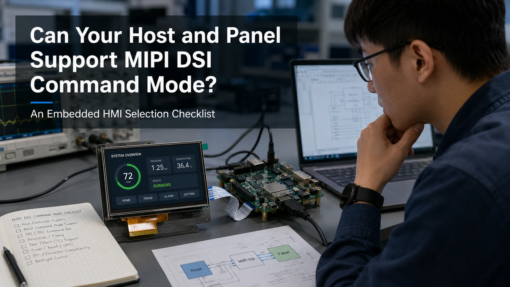
MIPI DSI Command Mode is suitable only when the display panel, host controller, software stack, and HMI update pattern support the same architecture. A MIPI DSI connector, lane count, or resolution does not confirm Command Mode capability. Before selecting it, verify the panel’s internal GRAM, memory-write commands, synchronization method, host DSI support, framebuffer strategy, initialization data, and required update rate. Otherwise, the project may need Video Mode, another panel, a modified display module, or a controller-based HMI solution.
Does the Display Panel Actually Support Command Mode?
Start with the exact display module and display driver IC. Do not infer the supported mode from screen size, resolution, connector shape, lane count, or the general description “MIPI DSI.”
Request or locate:
-
The complete display-module part number and revision
-
The display driver IC and revision
-
The panel or module specification
-
The initialization-command table
-
The declared DSI operating mode
-
Pixel formats
-
DCS and manufacturer-specific commands
-
Power and reset timing
-
TE or synchronization information
MIPI DSI defines the link between a host processor and a display module, while MIPI DCS defines standardized commands for display control and data transfer. The exact display implementation can still require panel-specific commands and operating conditions.
Confirm Internal GRAM and Memory-Write Support
A typical Command Mode design writes pixel data into display-side memory. Confirm that the panel or display controller provides the required GRAM and supports:
-
Column and page address windows
-
Full-frame memory writes
-
Partial-window writes
-
Memory-write start and continue commands
-
The required input pixel format
-
Defined behavior between host updates
ST’s TouchGFX Command Mode documentation specifically describes a display with DSI and GRAM and supports single, double, and partial-GRAM framebuffer strategies. This is a useful reminder that Command Mode is not simply a DSI configuration flag; the display-side memory architecture and driver functions must be available.
The final panel result may be Command Mode only, Video Mode only, both modes with different initialization sequences, or a more specialized implementation. Use the product specification as the controlling source.
Can the Host DSI Controller Generate Command Mode Traffic?
Panel support is only half of the decision. The selected MCU, MPU, SoC, SBC, or SoM must provide a compatible Command Mode data path.
Check the host documentation for:
-
DSI host-controller mode support
-
DSI PHY and lane availability
-
Low-power command transmission
-
Long-packet pixel transfer
-
Interrupt support
-
TE input support
-
DMA or display-controller integration
-
Maximum transfer rate
-
BSP, HAL, or kernel support
Separate processor capability from board-level availability. A processor may contain a suitable DSI controller while the production board does not route the required lanes, TE input, reset signal, or panel power controls.
Host support can also be limited by the current software implementation. Espressif’s ESP32-P4 documentation, for example, states that its video-stream output currently uses Video Mode and does not support Command Mode. The same documentation distinguishes DCS command transmission for initialization from the mode used to deliver continuous pixel data.
This is why the complete MIPI DSI compatibility checklist should be reviewed before the display is ordered. Mode support must be checked together with the host controller, lanes, timing, pinout, power, initialization, and operating system.
Do the Connector, FPC, Power, and TE Signals Support the Design?
A panel and host may both support Command Mode but still fail at the physical or electrical integration layer.
Compare:
-
Connector manufacturer and part number
-
Pin count and contact pitch
-
Pin 1 reference
-
Top-contact or bottom-contact FPC orientation
-
Clock and data-lane mapping
-
Ground positions
-
Panel logic and I/O voltage
-
Reset and enable pins
-
Backlight power, enable, and PWM
-
TE signal routing and voltage
-
Touch SDA, SCL, reset, and interrupt
-
FPC length, bend area, and exit direction
Do not treat a connector match as system compatibility. The connector can fit while the TE pin is absent, reset voltage is unsuitable, or the display supports only Video Mode.
TE is commonly used to coordinate pixel writes with the panel’s scan behavior and reduce visible tearing, but the requirement depends on the display driver IC, host architecture, and update method. Confirm whether TE is required, optional, or unsupported and how the host software is expected to use it.
Can the Driver Initialize and Write to the Panel Correctly?
A working Command Mode system requires more than host-controller support. The panel driver must perform the correct hardware reset, initialization, addressing, and pixel-transfer sequence.
Review whether the software provides:
-
Hardware reset and required delays
-
Sleep Out
-
Pixel-format selection
-
Address-mode or orientation settings
-
Column and page window setup
-
TE configuration
-
Display On
-
Memory-write commands
-
Manufacturer-specific register values
-
Suspend and resume handling
MIPI DCS standardizes many setup and control commands, including the supply of display data, but it does not remove the need to verify module-specific initialization.
Do Not Confuse Command Packets with Command Mode
A Video Mode display may still receive DCS commands for reset, Sleep Out, pixel format, brightness, or Display On. ST’s Video Mode example configures a continuously driven framebuffer path while still sending DCS initialization commands to the LCD controller.
The operating mode is determined by how pixel data reaches and refreshes the display, not merely by whether the host sends commands.
For Command Mode, the driver should also be able to:
-
Set the correct update rectangle
-
Send the selected pixel format
-
Start and continue memory writes
-
Coordinate transfers with TE or another timing method
-
Handle rotation and address mapping
-
Recover after reset, suspend, or interrupted transfers
If the initialization sequence or memory-write functions are unavailable, the panel should not be approved for Command Mode based only on its driver IC family.
Does Command Mode Match the HMI Update Pattern?
After confirming panel and host support, evaluate the application workload.
Command Mode is worth evaluating when most of the screen remains static and the application updates small regions such as:
-
Numeric values
-
Status indicators
-
Buttons
-
Warning icons
-
Progress bars
-
Periodic sensor readings
Potential benefits depend on the panel retaining the image in GRAM and the host efficiently writing only the changed area. The host driver, GUI framework, and synchronization path must support partial updates.
Video Mode may be a more practical starting point when the application uses:
-
Frequent full-screen animation
-
Smooth menu transitions
-
Camera preview
-
Video playback
-
Continuously changing graphics
-
A display pipeline designed around regular framebuffer scanning
ST documents separate TouchGFX workflows for Command Mode and Video Mode. Its Video Mode path uses LTDC and a framebuffer to transfer pixels continuously through the DSI host, while its Command Mode path is organized around transfers to display GRAM.
Do not reduce the decision to “static equals Command Mode” and “animation equals Video Mode.” A mostly static HMI may still require rapid full-screen transitions, while an animated interface may have a host and panel architecture that supports efficient command-based updates. The selection should follow the worst-case workload, not only the average screen state.
Can the Host Memory and Graphics Architecture Support the Mode?
Command Mode does not automatically eliminate host memory requirements. The GUI framework may still need a full, double, or partial framebuffer for rendering.
Calculate or review:
-
Framebuffer size
-
Pixel format
-
Single, double, or partial buffering
-
Internal versus external RAM
-
DMA support
-
Memory bandwidth
-
Cache behavior
-
Graphics accelerator support
-
Worst-case rendering time
-
Worst-case full-screen transfer time
Also verify the display-side limitations:
-
GRAM capacity
-
Maximum memory-write rate
-
DSI long-packet capability
-
Update-window overhead
-
TE timing
-
Maximum acceptable full-screen refresh time
A dashboard that usually changes only small values may still need a complete page transition. If that transition takes longer than the project permits, the average partial-update efficiency does not solve the user-experience problem.
Power should also be evaluated at the complete-system level. Command Mode may reduce DSI activity in some low-update applications, but total power also depends on host rendering, memory traffic, panel refresh behavior, lane rate, GUI activity, and backlight consumption.
MIPI DSI-2 supports GUI-oriented command modes, static modes, high-frame-rate video modes, and newer hybrid behavior. This broader architecture shows why one mode label is not enough to predict total power or performance.
Can the GUI Framework, BSP, and Device Tree Support the Design?
For an RTOS or MCU project, review how the GUI framework transfers completed regions to the display.
With LVGL, TouchGFX, or a custom GUI stack, check:
-
Flush-callback behavior
-
Full or partial framebuffer support
-
DMA transfer
-
TE synchronization
-
Update-window management
-
Rotation
-
Pixel-format conversion
-
Thread or interrupt coordination
TouchGFX provides separate configuration paths for MIPI DSI Command Mode and Video Mode. Its documentation also notes that a working LCD driver is required and that reference implementations do not cover every buffering strategy.
For Linux or Android, review:
-
DSI host driver
-
Panel driver
-
DSI mode flags
-
Initialization commands
-
Regulator controls
-
Reset GPIO
-
Backlight control
-
TE support
-
Display timing
-
Touch-controller driver
-
Suspend and resume
Device Tree can describe the hardware relationship, but it cannot create panel-side GRAM, add unsupported Command Mode functionality to the host, or replace an unavailable initialization sequence.
The BSP maintenance question is also important. Determine whether support is already available, can be adapted from an existing driver, depends on a vendor BSP, or would require a custom implementation that the OEM must maintain through future kernel or SDK updates.
What Failures Suggest the Selected Mode Is Wrong or Incomplete?
A mode or driver mismatch may produce:
-
A black screen after initialization
-
A panel that operates only in Video Mode
-
Successful commands but no visible pixels
-
Full-screen writes that work while partial updates fail
-
Tearing during regional updates
-
Incorrect update-window boundaries
-
Old pixels remaining on screen
-
Image shifts after rotation
-
Failure after suspend or resume
-
Backlight operation without GRAM updates
Check the panel mode declaration, initialization commands, pixel format, address window, transfer length, TE synchronization, reset sequence, and host DSI configuration.
These symptoms can also result from FPC, lane, power, or timing problems. Use broader troubleshooting before concluding that Command Mode itself is the cause.
Choose the Appropriate Display Integration Path
Proceed with a standard display module when the panel mode is documented, the host supports it, the connector and power design match, and the software path is available.
Consider a modified module when the Command Mode architecture is suitable but the project needs a different:
-
FPC length or exit direction
-
Connector
-
بيناوت
-
TE routing
-
Touch arrangement
-
Backlight configuration
A Custom Display Assembly may also integrate a cover lens, optical bonding, interface PCBA, brackets, or enclosure features.
When the host lacks a maintainable Command Mode implementation, or several processor platforms need a common display subsystem, a controller-based display or Modular HMI Solution may create a clearer hardware and software boundary.
عرض أيضًا embedded display solutions for FreeRTOS and Linux HMI include LVGL-, Qt-, MIPI DSI-, and touch-oriented product paths that can be evaluated against the host and application requirements.
إن 10.1-inch MIPI DSI touch display for embedded HMI is an example of a platform-oriented Touch Display Module with a published 1280×800 resolution, MIPI DSI interface, and I²C touch interface. Its public page does not identify Command Mode or Video Mode, so that property should be verified against the exact specification and driver documentation rather than inferred from the product category.
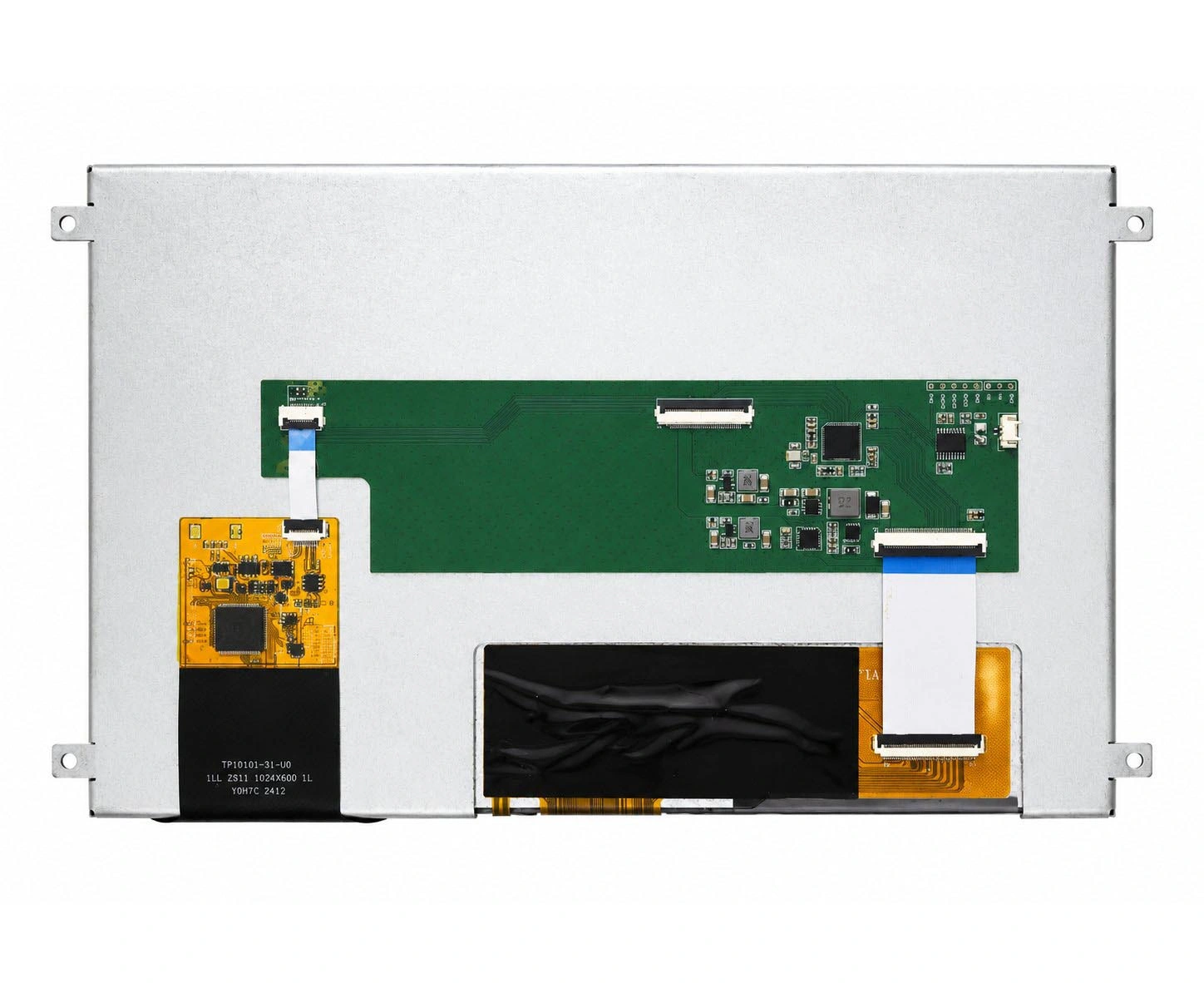
Kadi Display’s broader industrial display and integration solutions can support evaluation across the path from panel or touch module to custom assembly and embedded display architecture, depending on documented project needs.
استنتاج
Select MIPI DSI Command Mode in this order: verify panel architecture and GRAM, confirm host-controller support, check connector and TE routing, obtain the initialization and pixel-write driver, evaluate the GUI workload and memory architecture, and validate the complete system.
If Command Mode is being considered for a new HMI, discuss your embedded HMI display requirements with Kadi Display. Relevant inputs include the host processor or board, operating system or RTOS, GUI framework, display size and resolution, panel or driver IC, DSI mode documentation, lane count, typical update pattern, touch requirement, connector drawing, mechanical drawing, application, and expected project quantity. Kadi’s contact page accepts technical questions and custom-display requests.
أسئلة متكررة
Does MIPI DSI Command Mode Require Panel GRAM?
A typical Command Mode implementation writes pixel data into display-side memory, so GRAM and the required memory-write functions should be confirmed in the panel or driver IC documentation. Do not infer GRAM from the MIPI DSI interface label.
Can a Video Mode Display Receive DCS Commands?
Yes. A Video Mode display may use DCS commands for initialization and control while receiving pixel data through a continuous video stream. Command packets and Command Mode are different concepts.
Is Command Mode Better for a Static HMI?
It may suit a mostly static interface when the panel retains its image and supports efficient partial updates. Host support, full-screen transition time, software complexity, synchronization, and power still need to be evaluated.
Is a TE Signal Required?
The requirement depends on the panel and update architecture. TE can help synchronize pixel writes with panel scanning and reduce tearing, but the exact implementation should follow the display controller and host documentation.
Can Command Mode Be Enabled Only Through Device Tree?
Usually not. The panel architecture, host DSI controller, panel driver, initialization sequence, pixel-transfer functions, synchronization method, and GUI framework must all support the design.
السابق
MIPI DSI Power Sequencing and Reset Timing Check: Why a Compatible Panel Can Still Show a Black Screen
التالي
MIPI DSI Connector and FPC Pinout Check: How to Compare a Display Module with Your Host Board
اترك تعليق

آخر مدونة وأخبار
- MIPI DSI Display Driver Development for Embedded Linux What Hardware Buyers Need to Confirm
- Why LCD Screens Go Black Through Polarized Sunglasses and How to Prevent It
- How to Diagnose an LCD That Is Slow Flickers or Fails to Start in the Cold
- Why PCAP Touchscreens Need Retuning After Cover Glass Coating or Optical Bonding Changes
- Why Outdoor LCDs Fog Inside: Condensation, Sealing, Vents, and Heaters
مدونة ذات صلة وأخبار
-
 TN مقابل IPS2024-7-9
 -
TN مقابل IPS2024-7-9

