




الصفحة الرئيسية
-
مدونة & أخبار
-
Common MIPI DSI Display Problems: Black Screen, Flicker, No Backlight, and Driver Issues
Common MIPI DSI Display Problems: Black Screen, Flicker, No Backlight, and Driver Issues
2026-07-05
11:20
Common MIPI DSI Display Problems: Black Screen, Flicker, No Backlight, and Driver Issues
A Practical Troubleshooting Reference for Embedded Engineers
من إعداد الفريق الفني لشركة كادي ديسبلاي | www.kadidisplay.com
Introduction: Why MIPI DSI Display Failures Are More Common Than You Think
If you’ve ever stared at a powered-on embedded system with a completely dark panel and wondered where things went wrong, you’re not alone. MIPI DSI (Mobile Industry Processor Interface — Display Serial Interface) has become the dominant high-speed display protocol in embedded Linux, Android, and RTOS platforms. With lane speeds reaching up to 4.5 Gbps per lane in DSI-2 specification, it delivers the bandwidth needed for modern high-resolution panels. Yet that very complexity is why MIPI DSI black screen issues, display flicker, and driver initialization failures account for a disproportionate share of bring-up headaches in product development.
In a 2023 survey of embedded engineers across IoT and industrial display segments, display interface bring-up — including MIPI DSI — ranked as the second-most time-consuming hardware debugging task, trailing only power management. Typical bring-up time for a new DSI panel without a prior reference design ranged from 3 to 10 engineering days. This article walks through the most common failure modes, grouped by root cause, with actionable diagnostic steps for each.
Whether you’re working with a Raspberry Pi DSI display, a custom industrial TFT LCD module, or an AMOLED panel connected over MIPI DSI, the failure categories are consistently the same. Let’s break them down.
FPC Connector Problems: The Most Overlooked Cause of Black Screen
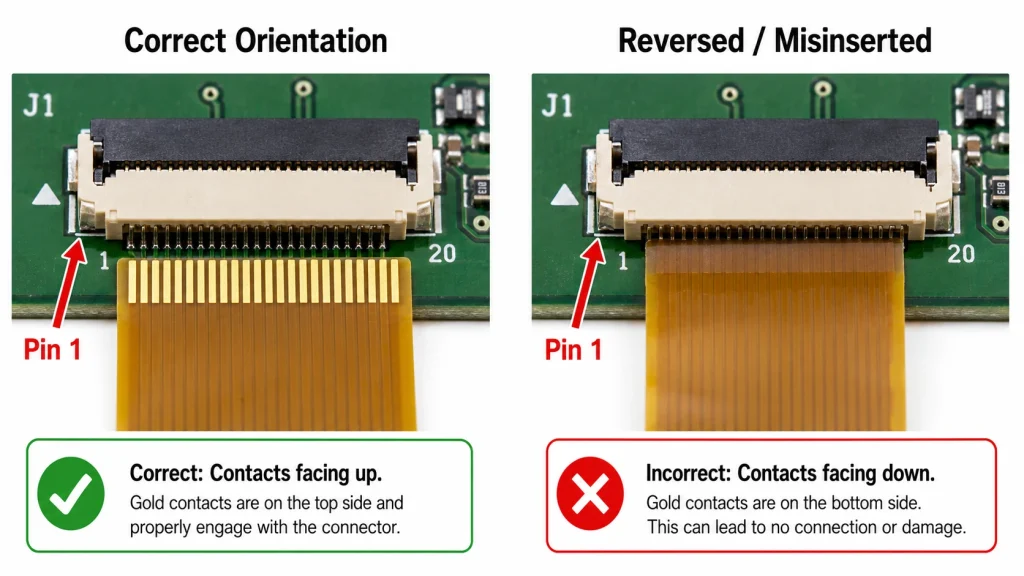
Before diving into software, always audit the physical layer first. Flexible Printed Circuit (FPC) connectors are physically reversible by design — a single 180-degree mistake means you’ve driven logic-level signals into power rails, or simply left data lines open. In production environments, FPC misinserts account for roughly 15–25% of display ‘no display’ failures on first assembly runs, according to manufacturing yield data from contract electronics manufacturers in Shenzhen.
How to check
- Locate pin 1 on both the FPC cable and the ZIF (Zero Insertion Force) connector. Pin 1 is usually marked with a small triangle, dot, or a color stripe on one edge of the FPC ribbon.
- Visually confirm that the metallic contact pads on the FPC face the correct direction — most ZIF connectors require contacts facing downward on bottom-contact designs. Check your display module datasheet.
- Inspect for partial insertion: the FPC should sit flush, with the retention bar fully clicked into the locked position. Even a 0.5 mm partial insertion can break contact on outer lanes.
- Check for pin contamination: oils from handling can cause intermittent contact on fine-pitch (0.5 mm or 0.3 mm) FPCs.
Pro tip: If the system shows a white screen, all-color screen, or random noise rather than black, the FPC is likely inserted but in an incorrect orientation — power and ground may have continuity, but data signals are swapped.
For MIPI DSI display modules with clearly marked FPC orientation guides, see the 5.0-inch 800×480 DSI MIPI Display for Raspberry Pi from Kadi Display.
Power Supply Issues: VDD, VDDIO, and Sequencing Failures
MIPI DSI panels typically require multiple supply rails operating within tight tolerances and — critically — a defined power-on sequence. Violating that sequence is a fast path to a black screen, even when all other configurations are correct.
Typical supply rails for a DSI TFT-LCD module
Measurement checklist
- Use an oscilloscope or precision multimeter to verify each rail under load, not just on the bench supply.
- Check power-on sequencing: most controllers require VDD to stabilize at least 1 ms before AVDD ramps, and the reset signal must be released only after all rails are stable.
- Verify current capacity: a 5-inch DSI display with backlight may draw 300–500 mA on AVDD alone. Undersized LDOs or long PCB traces can cause rail droop under load.
- Look for ripple: switching supplies feeding AVDD with more than 50 mV peak-to-peak ripple can cause periodic display flicker or color banding.
Common mistake: Engineers often set bench power supply current limiting too low. The panel fails to initialize because rush current during LCD charge pump startup triggers overcurrent protection — leaving a black screen with no obvious error in dmesg.
Backlight Not Working: LED Driver, PWM, and Enable Signal Faults
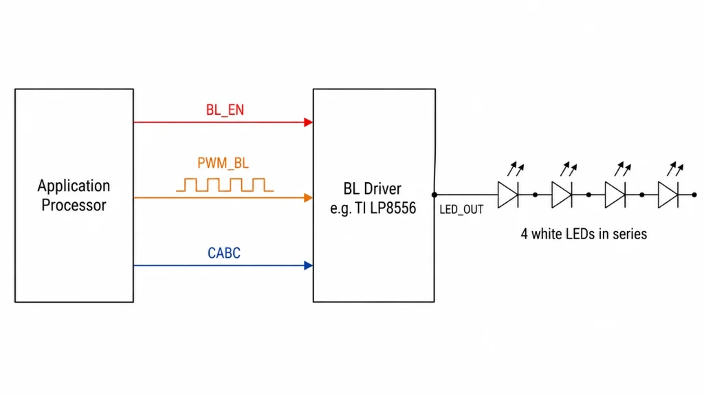
A dark panel with an otherwise working display is a backlight problem, not a MIPI DSI problem. These are two separate subsystems. If you can faintly see content by shining a flashlight at the panel at an angle, the LCD itself is displaying correctly — only the backlight LED driver has failed.
Step 1 — Check BL_EN (Backlight Enable)
This GPIO signal must be driven HIGH by the SoC before the LED driver IC activates. On Linux, confirm the GPIO state:
Step 2 — Check PWM signal
Most LED driver ICs (e.g., TI LP8556, Maxim MAX8831) require a PWM signal to set brightness. A duty cycle of 0% means zero brightness — effectively no backlight, even if BL_EN is asserted. Measure with an oscilloscope: frequency typically 1 kHz – 50 kHz, duty cycle non-zero at boot.
Step 3 — I²C register dump (if applicable)
Many modern LED drivers are controlled via I²C. Check that the bus is functional and the driver has written configuration registers:
Step 4 — CABC (Content Adaptive Brightness Control)
If CABC is misconfigured via DSI DCS commands, the panel controller may override PWM brightness to zero. Disable CABC temporarily during bring-up by sending the appropriate DCS command in your panel init sequence.
Device Tree Configuration: The Most Error-Prone Software Layer
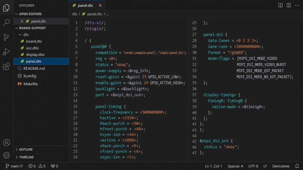
On embedded Linux systems — Yocto, Buildroot, or Android BSP — the Device Tree (DT) is the primary mechanism for communicating display panel parameters to the kernel MIPI DSI host driver. A misconfigured DT node is responsible for a large category of MIPI DSI not working situations where hardware is physically correct but the panel never initializes.
Example DT node structure
Most common DT mistakes and their symptoms
Debugging with dmesg
Look for: panel-simple: error -ENODEV, dsi host not found, failed to get DSI bus, or drm_bridge: failed to attach. These messages point directly to DT binding failures.
Panel Driver and DCS Command Sequence Issues
Even with correct hardware and Device Tree, many MIPI DSI panels require a specific initialization sequence — a series of MIPI DCS (Display Command Set) or vendor-specific commands sent via the DSI LP (Low Power) mode before the panel transitions to HS (High Speed) video mode. Getting this wrong produces a black screen that looks identical to a hardware failure.
Exit Sleep command timing
The DCS exit_sleep_mode command (0x11) requires a mandatory 5 ms delay afterward per MIPI DCS specification. Many panel ICs extend this to 120–200 ms. Sending display_on (0x29) before this delay expires results in no display output.
MIPI switch from LP to HS mode
The panel’s internal DSI receiver must complete initialization before the host switches from Low Power to High Speed video streaming. Premature HS mode entry causes DSI synchronization failures and a black screen.
Vendor-specific register unlocking
Many panel ICs (e.g., Novatek NT35521, Sitronix ST7701, Himax HX8394) require writing a manufacturer-specific ‘magic key’ to a command register before any other configuration can be applied. Missing this step means all subsequent commands are silently ignored.
Debugging approach
Use a MIPI protocol analyzer to capture the actual command stream and compare against the panel datasheet initialization sequence. Alternatively, add kernel trace statements inside the panel driver’s prepare() or enable() callbacks to confirm commands are being sent.
MIPI DSI Timing Configuration: Clock, Blanking, and Lane Settings
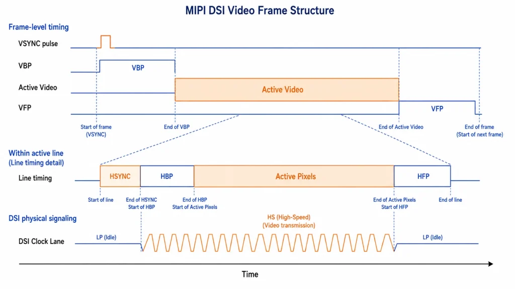
Timing misconfiguration is the root cause of display flicker, vertical tearing, and intermittent blanking on MIPI DSI displays — even when the panel initializes correctly and shows an image.
Pixel clock calculation
If the programmed DSI clock deviates from the calculated value by more than the panel IC’s tolerance (typically ±3%), you will see persistent display flicker, lane synchronization errors, or intermittent black frames.
Timing-related symptoms and causes
Step-by-Step MIPI DSI Debug Workflow
Phase 1 — Hardware sanity (Day 1, 0–2 hours)
- Verify FPC orientation and seating (Section 1).
- Measure all supply rails with oscilloscope under load.
- Confirm RESET signal is toggling correctly (logic analyzer).
- Check backlight BL_EN and PWM signals.
Phase 2 — Kernel driver confirmation (Day 1, 2–4 hours)
- Check dmesg for panel probe, DRM bind, and any error codes.
- Verify Device Tree node is correct and status = “okay”.
- Confirm panel driver is compiled and loaded: lsmod | grep panel
- Attempt manual framebuffer write: dd if=/dev/urandom of=/dev/fb0 bs=1M count=1
Phase 3 — Protocol-level debug (Day 2+)
- Capture DSI LP initialization traffic with protocol analyzer.
- Compare captured DCS command sequence against panel datasheet.
- Verify pixel clock and blanking parameters match panel spec.
- Enable DRM debug output and check for FIFO underrun errors:
Choosing the Right Display Module to Minimize Bring-Up Complexity
One practical way to reduce MIPI DSI bring-up time is to choose display modules from manufacturers who provide complete reference BSP packages, Device Tree examples, and verified driver code.
Kadi Display’s industrial TFT LCD and MIPI DSI display lineup includes modules targeted at Raspberry Pi, Rockchip, and Allwinner platform integration, with 1400 nit high-brightness options for outdoor use and wide-temperature variants for industrial environments.
Their Displays for Raspberry Pi category lists MIPI DSI panels pre-validated against Raspberry Pi 4 and Raspberry Pi 5, significantly reducing driver and DT bring-up burden.
For industrial TFT LCD modules with full documentation, see: https://www.kadidisplay.com/product_category/displays-tft-lcd/
Vendor evaluation criteria
- Availability of panel datasheet with complete initialization sequence.
- Reference DTS (Device Tree Source) file for your target SoC.
- Known good kernel version and driver tree.
- Clear FPC pinout documentation with pin 1 marking.
- Verified power sequencing diagram.
Quick Reference: MIPI DSI Troubleshooting Checklist
استنتاج
MIPI DSI display problems — whether a stubborn black screen, persistent flicker, a dead backlight, or a panel that simply refuses to initialize — are almost always traceable to one of the root causes covered in this guide: physical connector problems, power rail faults, backlight driver misconfiguration, Device Tree errors, incorrect panel initialization sequences, or timing parameter mismatches.
The structured, phase-based debug approach — starting with hardware and working up to protocol-level analysis — prevents engineers from spending days in driver code when the real problem is a reversed FPC or a drooping AVDD rail.
Selecting display modules with good documentation, reference drivers, and proven compatibility with your target platform remains the single most effective way to reduce MIPI DSI bring-up time. Investing 30 minutes reading a panel datasheet thoroughly before writing a single line of driver code will consistently pay dividends.
For display module inquiries, custom MIPI DSI panel solutions, and industrial TFT LCD sourcing, visit عرض كادي — a professional display manufacturer with over 20 years of industry experience.
السابق
Industrial LCD Failure Modes: Image Retention, Burn-in, Mura, Spot Damage and Backlight Aging
التالي
ZIF Connectors for Capacitive Touch Panels: Avoiding GT911 Touch Failures from FPC Contact Problems
اترك تعليق

آخر مدونة وأخبار
- Industrial LCD EOL: What Happens from Pre-Announcement to Replacement Mass Production?
- Electronic Component Obsolescence Management for Industrial Displays: An OEM Guide
- How to Develop a Production Ready Custom Display Assembly TFT Module Touch Cover Glass FPC Bonding and Mounting
- 15 Pin vs 22 Pin Raspberry Pi DSI Connectors Cable Pinout and Compatibility
- Native MIPI DSI vs LVDS or HDMI Bridge: An OEM Display Architecture Decision Guide
مدونة ذات صلة وأخبار
-
 TN مقابل IPS2024-7-9
 -
TN مقابل IPS2024-7-9

