




الصفحة الرئيسية
-
مدونة & أخبار
-
MIPI DSI Image Is Present but Corrupted: Pixel Format, Timing, Driver, and Signal-Path Checks
MIPI DSI Image Is Present but Corrupted: Pixel Format, Timing, Driver, and Signal-Path Checks
2026-09-03
00:00
If a MIPI DSI image is present but corrupted, the display has already passed several basic bring-up stages. Instead of restarting black-screen troubleshooting, classify what is wrong with the visible image. Wrong colors usually point you toward pixel-format or initialization settings; shifted or partial images make timing and mode configuration more important; changing or intermittent corruption raises questions about the FPC, connector, or signal path.
The objective is to identify the failed layer before changing the display module or carrier hardware.
Quick Check: What Kind of Image Corruption Do You Actually Have?
Start with the visible symptom. Different artifacts should not lead to the same troubleshooting path.
| Visible Symptom | Check First | الطبقة المحتملة |
|---|---|---|
| Geometry correct, colors wrong | Pixel format and panel color configuration | Driver / initialization |
| Image shifted, repeated, or stretched | Timing, active area, operating mode | DSI configuration |
| Partial or cropped image | Resolution, timing, addressing | Driver / panel configuration |
| Random or changing corruption | FPC, connector, signal path | Interconnect |
| Fixed vertical or horizontal line | Check whether defect follows panel coordinates | Panel / internal interconnect |
| Corruption changes when FPC is moved or reseated | Connector and FPC | Physical path |
This distinction matters because a fixed line at the same physical row or column can belong to a different failure class from data corruption that changes with content or cable position. Kadi’s published LCD defect classification treats lines as defects that should first be classified by appearance and location rather than automatically blamed on the video interface.
If the panel is completely black, does not probe, or has no backlight, this article is no longer the right troubleshooting path. Those symptoms belong to earlier bring-up stages.
Test With Simple Patterns Before Changing the Driver
Before editing timing tables or replacing the module, display a few controlled patterns:
-
solid red, green, and blue;
-
white and black;
-
simple color bars;
-
a grid or rectangles with known dimensions.
Then observe what changes.
Does the artifact stay in exactly the same physical location? Does it move when the image content changes? Are all colors wrong, or only some? Does the damaged area change after reboot? Does reseating the FPC change the pattern?
These tests turn a vague description such as “the image looks wrong” into more useful evidence.
A fixed line that remains in the same panel coordinate across several test patterns deserves a panel-defect investigation. A pattern that changes when the interconnect is moved deserves attention at the FPC or connector layer.
Root Cause 1: The Pixel Format Does Not Match the Panel Configuration
If image geometry is correct but the colors are obviously wrong, start with pixel format before investigating PCB signal integrity.
A MIPI DSI system can involve three related color-format settings:
framebuffer or host format → transmitted DSI pixel format → panel-controller pixel format
Those settings need to agree with the exact implementation.
Common MIPI DSI input formats include RGB565, RGB666, and RGB888. Espressif’s MIPI DSI documentation, for example, describes these formats and notes that the panel color depth can be configured through the DCS Pixel Format Set command, while the exact command parameter must be checked against the LCD controller datasheet.
That leads to a useful diagnostic rule:
If the geometry, refresh behavior, and active area look correct but the entire screen has incorrect colors, verify pixel-format agreement first.
Check:
-
framebuffer format;
-
host DSI output format;
-
DSI data type where applicable;
-
panel initialization setting for color depth;
-
whether the driver was originally written for the exact panel/controller variant.
Do not assume that a driver is correct simply because it produces a visible image.
Kadi’s MIPI DSI panel driver compatibility article similarly recommends checking pixel format together with timing, lane count, operating mode, initialization, reset, and power behavior when deciding whether an existing driver really matches a panel.
Root Cause 2: Timing or Display Mode Is Producing the Wrong Geometry
If colors are mostly correct but the image is shifted, compressed, repeated, cropped, or partially missing, investigate timing and operating mode.
Important parameters can include:
-
horizontal and vertical active resolution;
-
front and back porch values;
-
sync widths;
-
pixel clock;
-
refresh rate;
-
DSI operating mode;
-
panel addressing or initialization settings where relevant.
A timing mismatch does not have to produce a completely black screen. It can also produce a visible image with the wrong active area or geometry.
Kadi’s existing guide to MIPI DSI timing parameters explains pixel clock, active pixels, porches, sync widths, and refresh rate in more detail. It also notes that a correct timing table alone does not establish complete compatibility because lane count, bandwidth, connector pinout, power, initialization, driver support, and system validation still matter.
For this troubleshooting stage, do not change multiple timing parameters simultaneously. Compare the actual host configuration against the exact panel specification and isolate one difference at a time.
Root Cause 3: The Driver Loads, but the Panel Configuration Is Still Wrong
A working driver is not the same thing as a correct driver configuration.
If an image appears, the software stack is clearly doing useful work. But the panel may still be initialized with the wrong:
-
pixel format;
-
timing;
-
DSI mode;
-
lane configuration;
-
mode flags;
-
address or orientation settings;
-
controller-specific initialization sequence.
This becomes particularly important when a driver was adapted from another panel with the same resolution or a related controller.
Matching resolution does not establish panel compatibility. Even two displays with the same connector can require different electrical, initialization, timing, or software behavior.
When the existing driver is close to the correct configuration, modifying its panel-specific settings may be more appropriate than selecting another display. When the initialization or controller behavior differs substantially, the project may need a different driver path.
The decision should follow the exact panel and host documentation rather than the fact that “something appears on screen.”
Root Cause 4: Is That Vertical Line a Panel Defect or Data Corruption?
Vertical lines deserve their own classification because they can easily send troubleshooting in the wrong direction.
If one line stays at exactly the same physical column through red, green, blue, white, and black patterns—and remains unchanged when the source content moves—the problem is more consistent with a panel-coordinate or internal interconnect defect than with changing image data.
Kadi’s published LCD defect material separates line defects from other visual abnormalities and discusses row/gate and column/source drive paths as relevant categories.
The situation is different when you see:
-
changing bands;
-
random lines;
-
blocks of corrupt pixels;
-
corruption that changes after reboot;
-
artifacts affected by cable position.
Those symptoms justify moving toward the interface and signal path.
Do not use a rule such as “vertical lines mean a MIPI lane problem.” The visual evidence should decide which layer you investigate next.
Root Cause 5: The FPC, Connector, or Signal Path Is Intermittent
Once pixel format, timing, and panel configuration are reasonably understood, inspect the physical path if the corruption is unstable.
Check the FPC for correct insertion and orientation. Confirm that the locking mechanism is fully engaged and inspect the contact area for visible contamination or damage. Compare the pinout against the actual host and display documentation rather than relying only on connector pitch or pin count.
If possible, compare the same display module on known-working reference hardware.
Useful evidence includes:
-
corruption changes after reseating the FPC;
-
artifacts change when the cable is moved;
-
the reference platform works but the production carrier does not;
-
the fault appears only in the final cable or connector arrangement.
Kadi’s existing connector troubleshooting content also uses changing or intermittent display corruption as a clue for investigating FPC and connector integrity.
For PCB-level MIPI DSI analysis, avoid universal assumptions about trace length, skew, impedance, or maximum FPC length. Those requirements depend on the host, module, actual PCB stack-up, interconnect, and vendor hardware-design guidance.
Fix the Right Layer: Parameters, Driver, FPC, Module, or PCBA?
The purpose of troubleshooting is to identify the smallest justified change.
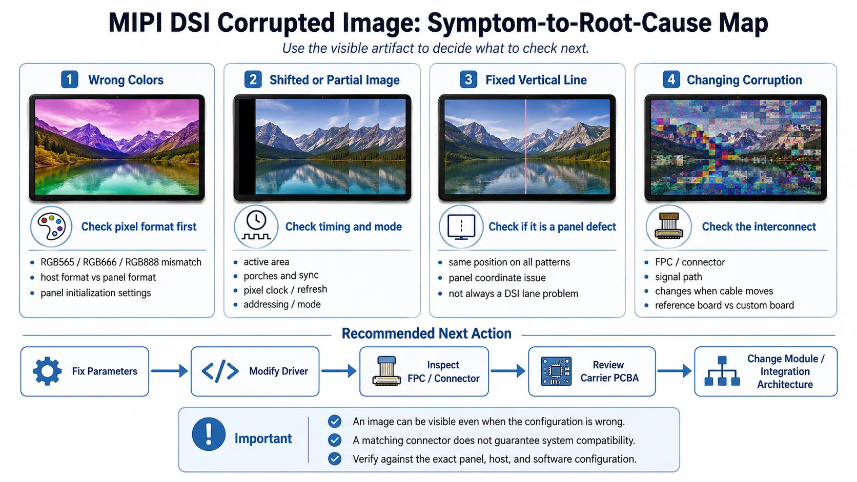
If colors are wrong but geometry is correct, start with pixel format and initialization.
If geometry is wrong, compare timing, mode, and addressing.
If the driver is close but does not match the exact panel behavior, modify the driver configuration.
If the corruption clearly changes with cable position or connector engagement, inspect or redesign the FPC/interconnect before replacing the display.
If the same display works on reference hardware but not on the production board, review what changed in the carrier-board signal and interface path.
A different display module becomes more relevant when the existing module is poorly matched to the host architecture or requires multiple adaptations across software, FPC, controller electronics, and mechanical integration.
For example, Kadi’s 10.1-inch 1200×1920 MIPI DSI display for Raspberry Pi CM4/CM5 is published as a specific MIPI DSI product with its own display architecture and Raspberry Pi integration information. It is useful as an example of a platform-specific implementation, not as evidence that one driver, timing table, or interconnect works across other panels.
The practical rule is:
Do not replace a display module to fix a pixel-format mismatch. Do not keep changing driver parameters when the corruption clearly follows the physical interconnect.
Which Display Integration Level Fits the Project?
A standard TFT or touch display module may still be appropriate when the interface already matches and the remaining problem is a correctable timing, initialization, or software configuration issue.
A custom display assembly becomes more relevant when the production design needs a different FPC, connector arrangement, touch integration, or mechanical interface.
A more modular embedded display architecture may be worth evaluating when display, touch, converter/controller electronics, Linux integration, and the host platform are becoming one combined engineering problem.
عرض كادي currently presents products and solutions across TFT displays, touch displays, Raspberry Pi displays, embedded solutions, monitors, and customized display paths rather than only bare panels.
The correct integration level depends on the exact host, display specification, driver path, physical interconnect, and production design.
What Information Should You Prepare Before Requesting Display Integration Support?
If the corrupted-image problem reveals that the existing display architecture may need modification, prepare information that helps identify the failing layer:
-
host processor, SoC, or SoM;
-
development or carrier-board model;
-
exact display/module part number;
-
resolution;
-
DSI lane count;
-
pixel format;
-
DSI mode if known;
-
OS/BSP/kernel where relevant;
-
driver or controller information;
-
panel datasheet and timing information;
-
a clear photo or screenshot of the corrupted image;
-
whether the artifact stays fixed or changes with content;
-
whether FPC reseating changes the symptom;
-
connector and pinout information where available.
If mechanical adaptation may be involved, include the relevant drawing or available installation space.
استنتاج
When a MIPI DSI image is visible but corrupted, use the artifact as diagnostic evidence. Wrong colors, incorrect geometry, fixed lines, and changing corruption should lead to different checks.
Start with pixel format, then timing and driver configuration. Separate fixed panel defects from content-dependent artifacts, and move to the FPC, connector, or carrier signal path when the evidence points there.
If the project requires a different display module, FPC arrangement, interface architecture, or integration approach, you can اتصل بـ Kadi Display with the host platform, display model, resolution, DSI configuration, relevant software information, panel specification, and a photo of the artifact to discuss suitable display options. Kadi’s contact page publicly accepts technical questions and custom-display requests.
Compatibility should be verified against the exact panel, host platform, driver configuration, interconnect, and complete system.
الأسئلة الشائعة
Why does my MIPI DSI display show the correct image shape but wrong colors?
Check whether the host framebuffer format, transmitted DSI pixel format, and panel-controller pixel format agree. RGB565, RGB666, and RGB888 are different formats, and the controller must be initialized for the intended format.
Can incorrect MIPI DSI timing cause a distorted or partial image?
Yes. Incorrect active-area, porch, sync, pixel-clock, or related mode settings can affect image geometry and stability. Compare the host configuration with the exact panel timing specification.
Does a vertical line mean the MIPI DSI signal is bad?
Not necessarily. A line fixed at the same physical panel coordinate can belong to a panel or internal interconnect defect class. Changing, intermittent, or cable-sensitive corruption should lead you toward the interconnect and signal path instead.
Should I replace the display if the image is corrupted?
Not before identifying the failed layer. Pixel-format, timing, initialization, driver, FPC, and carrier-board problems can all produce a visible but incorrect image. A module change makes more sense when the evidence shows that the existing display architecture is poorly matched to the production system.
Is the same MIPI DSI connector enough to confirm compatibility?
No. Physical connection is only one layer. Pinout, lane configuration, timing, pixel format, power, initialization, driver support, and system validation must also match the actual host and display implementation.
السابق
MIPI DSI Works After Power-On but Goes Black After Warm Reboot: Reset and Reinitialization Checks
التالي
MIPI DSI Works on the Development Board but Not on the Custom Carrier Board: A Step-by-Step Debugging Checklist
اترك تعليق

آخر مدونة وأخبار
- Industrial LCD EOL: What Happens from Pre-Announcement to Replacement Mass Production?
- Electronic Component Obsolescence Management for Industrial Displays: An OEM Guide
- How to Develop a Production Ready Custom Display Assembly TFT Module Touch Cover Glass FPC Bonding and Mounting
- 15 Pin vs 22 Pin Raspberry Pi DSI Connectors Cable Pinout and Compatibility
- Native MIPI DSI vs LVDS or HDMI Bridge: An OEM Display Architecture Decision Guide
مدونة ذات صلة وأخبار
-
 TN مقابل IPS2024-7-9
 -
TN مقابل IPS2024-7-9

