




Home
-
Blog & News
-
Can You Reuse a MIPI DSI Display Across SBCs and SoMs? A Host Migration Checklist
Can You Reuse a MIPI DSI Display Across SBCs and SoMs? A Host Migration Checklist
2026-08-13
11:09
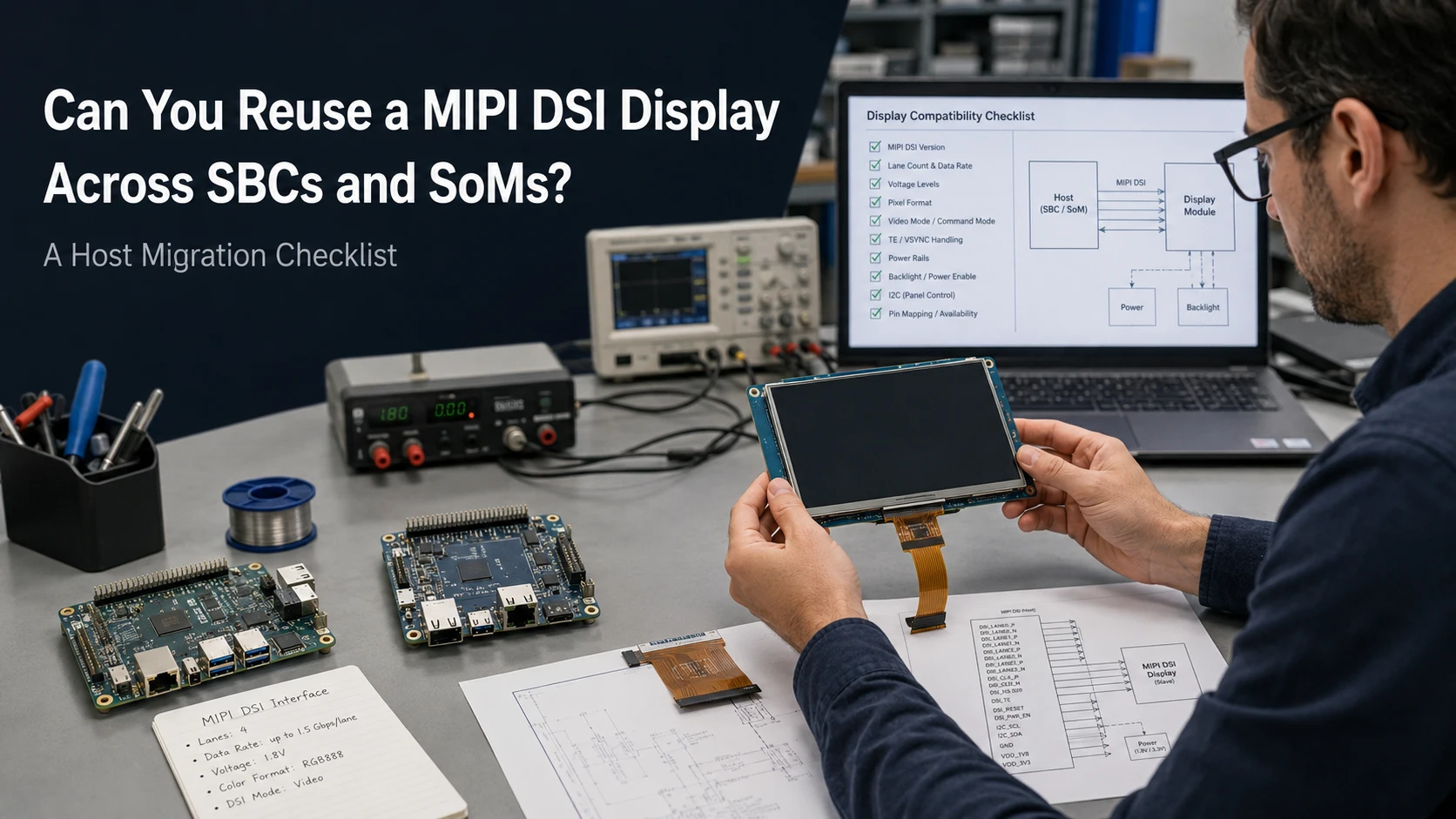
A MIPI DSI display that works on one SBC or SoM may work on another, but the original MIPI DSI display compatibility result does not transfer automatically. The target host must be checked for an accessible DSI output, connector and FPC mapping, lane capability, panel timing, power and reset control, software support, touch integration, and mechanical fit. Treat the migration as a new system-level compatibility review—not as a cable replacement.
Define Host A, Host B, and the Exact Display Module
Start by identifying the three parts of the migration:
-
Host A: the SBC, SoM, development board, or carrier board on which the display currently works.
-
Host B: the platform to which the display will be moved.
-
Display: the exact TFT or touch display module, including its revision.
Record the SoM, carrier-board, and display part numbers rather than using general descriptions such as “an i.MX board” or “a 10.1-inch DSI screen.” Board revisions matter because signal routing, connectors, GPIO assignments, and power-control circuits can change.
The comparison should also include:
-
Display driver IC
-
Touch-controller part number
-
Current and target operating systems
-
BSP and kernel versions
-
Current panel driver or initialization source
-
Device Tree or overlay files
-
Connector and FPC drawings
A working display on Host A proves that the module can operate under one defined combination of hardware and software. It does not prove that Host B provides the same signals, voltage rails, initialization sequence, or mechanical arrangement.
Use the complete MIPI DSI compatibility checklist as the broader reference for host-controller, lane, timing, pinout, power, initialization, and software checks. The migration checklist below focuses on which of those conditions must be reverified when the host changes.
Does the New SBC or SoM Expose a Usable MIPI DSI Interface?
MIPI DSI defines a high-speed serial interface between a host processor and a display module. That interface definition does not mean every SoC, SoM, and carrier board exposes DSI in the same way.
Distinguish SoC Capability from Board-Level Availability
A processor data sheet may list one or more DSI host controllers, but the finished hardware must still route the required signals through the SoM and carrier board.
For Host B, confirm:
-
The SoC contains a suitable DSI host controller.
-
The selected SoM configuration exposes that controller.
-
The carrier board routes the DSI clock and required data lanes.
-
A connector or board-to-board interface is physically available.
-
The connector is assigned to display output rather than camera input.
-
The selected BSP enables the DSI controller.
-
The required display pipeline is not reserved for another output.
Some platform ecosystems use a dedicated display adapter between the carrier board and display. Toradex, for example, documents a DSI Display Adapter for connecting DSI displays to specified Verdin and Aquila carrier boards. It also provides separate DSI-to-HDMI and DSI-to-LVDS adapters, illustrating that the appropriate migration route may involve interface conversion rather than a direct FPC connection.
If Host B does not expose a usable DSI interface, stop the direct-reuse review. The practical alternatives are a carrier-board redesign, a bridge or controller board, another display interface, or a modular HMI architecture.
Do the Connector, FPC, and Pin Assignments Match?
The same connector shape or pin count does not confirm compatibility.
Compare the Mechanical Connector Details
Obtain the host connector drawing and display FPC drawing. Compare:
-
Pin count
-
Contact pitch
-
Connector manufacturer and part number
-
FPC thickness
-
Exposed contact length
-
Top-contact or bottom-contact orientation
-
Pin 1 location
-
Same-side or opposite-side cable contacts
-
Latch construction
-
Cable insertion direction
-
Available connector clearance
Raspberry Pi provides a platform-specific example. Raspberry Pi 5 uses a different-sized DSI connector from earlier boards, and its official Touch Display connection uses a defined 22-way-to-15-way FFC. That cable arrangement belongs to the specified Raspberry Pi system; it is not a universal conversion between any 22-pin host and any 15-pin display.
Compare Every Pin Assignment
Create a Host A–Host B–Display mapping for:
-
DSI clock P/N
-
Data lane P/N pairs
-
Lane order
-
Ground pins
-
Panel logic power
-
I/O power
-
Reset and enable
-
Backlight power
-
Backlight enable and PWM
-
Touch SDA and SCL
-
Touch reset and interrupt
-
TE or synchronization signals
-
Reserved and no-connect pins
A passive FPC or adapter PCB may change connector format, contact orientation, pitch, or compatible signal order. It cannot create missing DSI lanes, convert an unsuitable voltage, supply unsupported panel timing, or provide missing driver software.
Can the New Host Generate the Required DSI Signal?
Once the physical connection is understood, compare the actual display-link requirements.
Check Lane Count and Lane Capability
Confirm:
-
Number of data lanes required by the display
-
Number of lanes implemented by Host B
-
Number of lanes routed through the SoM and carrier board
-
Supported per-lane data-rate range
-
Clock configuration
-
Differential-pair mapping and polarity
-
Supported PHY configuration
Do not rely only on the SoC’s maximum specification. A four-lane controller does not provide four-lane operation if only two lanes reach the connector.
Compare Complete Panel Timing
The active resolution is only part of the display timing. Recheck:
-
Horizontal active pixels
-
Horizontal front and back porch
-
Horizontal sync width
-
Vertical active lines
-
Vertical front and back porch
-
Vertical sync width
-
Pixel clock
-
Refresh rate
Two panels with the same resolution may require different blanking intervals, pixel clocks, and DSI lane rates.
Also confirm:
-
RGB565, RGB666, or RGB888 pixel format
-
Video mode or command mode
-
Burst or non-burst operation
-
Continuous or non-continuous clock
-
Panel-specific DSI mode flags
-
Manufacturer initialization requirements
A host that can produce the correct resolution through HDMI or LVDS does not necessarily support the panel’s native DSI timing and operating mode.
Do Power, Reset, Backlight, and Touch Still Work on Host B?
Moving the panel to another host changes more than the video source.
Compare Panel and Backlight Power
Verify the exact module requirements for:
-
Panel logic voltage
-
I/O voltage
-
Backlight input voltage
-
Required current
-
Regulator sequencing
-
Reset polarity and voltage
-
Reset pulse width
-
Delays before and after reset
-
Backlight enable polarity
-
PWM level and frequency requirements
Do not transfer voltage or reset assumptions from Host A without checking Host B’s schematic. A connector adapter cannot correct an unsuitable power rail unless it includes the required active circuitry.
The backlight should be treated separately from the image path. A lit backlight does not confirm that the panel received valid initialization commands or DSI video.
Treat Touch as a Separate Interface
A touch display module may use MIPI DSI for video while touch communication uses I²C, USB, or SPI. Recheck:
-
Available touch bus
-
Touch-controller voltage
-
I²C address, when applicable
-
Reset and interrupt GPIOs
-
Touch driver
-
Coordinate rotation
-
Display and touch orientation
-
Whether touch and display share one FPC
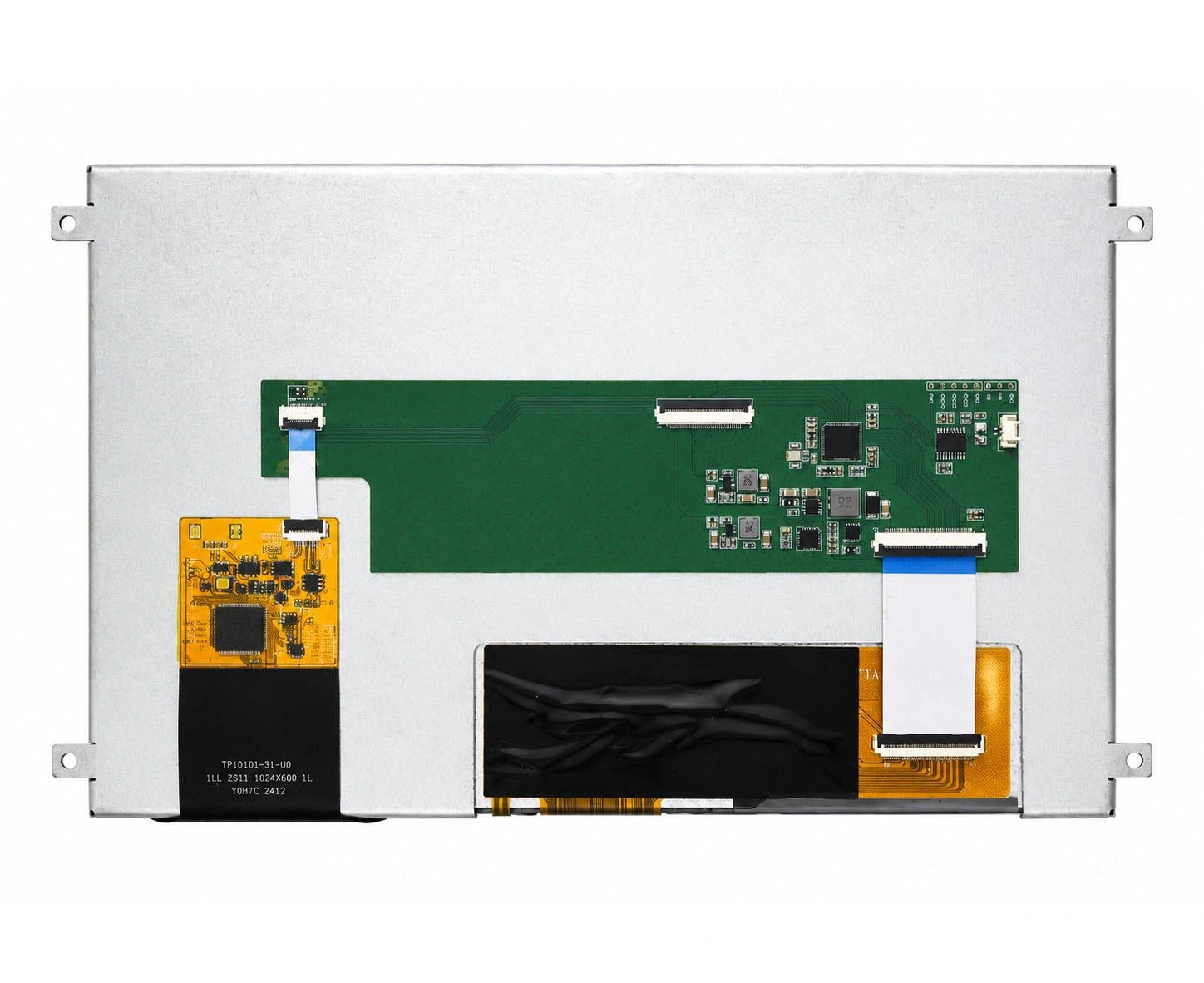
The 10.1-inch MIPI DSI touch display for embedded SBCs is an example of a platform-oriented module whose published information includes a 1280×800 DSI display and an I²C touch interface for selected embedded applications. A different host, carrier-board revision, or software image still requires a separate system review.
Can the Panel Driver and Device Tree Move to the New Platform?
Hardware compatibility does not automatically transfer the software implementation.
Separate the Software Components
A Linux MIPI DSI display path may include:
-
SoC DSI host-controller driver
-
DSI PHY driver
-
Panel driver
-
Bridge driver
-
Backlight driver
-
Touch-controller driver
-
Device Tree description
-
Bootloader display configuration
The panel driver describes panel-specific behavior. It does not replace the target SoC’s DSI host driver, PHY implementation, regulator framework, or carrier-board GPIO definitions.
Review the Panel Driver
Determine whether Host B’s BSP contains a driver for the exact panel or whether the existing driver can be adapted. Check:
-
Panel identification
-
Initialization command table
-
DSI mode flags
-
Lane count
-
Pixel format
-
Display timings
-
Supply controls
-
Reset sequence
-
Backlight control
-
Suspend and resume behavior
Linux DRM separates panel preparation from visible enable. The panel’s prepare stage can handle supplies, reset, and initialization, while enable makes the display visible. The corresponding disable and unprepare stages manage shutdown. This lifecycle means a driver that works on Host A may still require changes to power, GPIO, or sequencing behavior on Host B.
Rebuild the Device Tree for Host B
Review the target platform’s:
-
DSI host node
-
Panel compatible string
-
Endpoint connections
-
Data-lane assignment
-
Regulators
-
Reset and enable GPIOs
-
Backlight node
-
Display timing
-
Touch-controller node
-
Carrier-board pin configuration
Copying an overlay from Host A may reproduce the panel settings while retaining incorrect controller paths, regulators, GPIO numbers, or board-level dependencies.
Also establish whether the bootloader initializes the display. Host A may leave the panel active before Linux starts, while Host B may expect the kernel to perform the complete sequence.
Will the Display Fit the New Carrier Board and Enclosure?
Electrical compatibility can still produce an impractical assembly.
Review:
-
FPC length and exit direction
-
Available bend area
-
Connector access during assembly
-
Carrier-board position
-
Display orientation
-
Mounting-hole locations
-
Brackets and standoffs
-
Touch active-area alignment
-
Cover-lens outline
-
Enclosure clearance
-
Cable strain
-
Access for servicing
A connector placed on the opposite edge of Host B may require a longer or differently oriented FPC. A cable that crosses a mounting post, folds over a hot component, or cannot be inserted after enclosure assembly creates a production risk.
Where the electrical interface is suitable but the connector, FPC, touch structure, cover lens, bonding, or brackets do not fit, custom display assembly and interface options may provide a more appropriate route than redesigning the complete device around a standard module. Kadi’s public customized-display category identifies interface, board-compatibility, brightness, thickness, and enclosure-related options that can be evaluated against documented project requirements.
Choose the Appropriate Host-Migration Path
Use the completed evidence to classify the project:
| Integration path | Appropriate when | Main limitation |
|---|---|---|
| Direct reuse | Connector, pinout, lanes, timing, power, software, touch, and mechanics match | Complete-system validation is still required |
| Passive FPC or adapter | Differences are limited to compatible connector format or pin order | Cannot solve voltage, lane, timing, or driver incompatibility |
| Software adaptation | Hardware is compatible and the BSP can support the panel | Requires driver and Device Tree work |
| Carrier-board modification | DSI is available but routing, power, reset, or connector design differs | Requires board redesign and validation |
| Modified display module | Core DSI requirements match but FPC, connector, touch, or mechanics differ | Must be reviewed against exact drawings |
| Custom display assembly | The project requires integrated touch, cover lens, bonding, PCBA, or mounting | Requires complete electrical and mechanical inputs |
| Modular HMI or controller solution | Native DSI creates excessive host-specific dependency | Changes the interface, power, software, and mechanical architecture |
This is where display selection moves beyond a Bare TFT Panel. A production device may require a Touch Display Module, a Custom Display Assembly, or a Modular HMI Solution depending on how much host-specific engineering the OEM wants to maintain.
Kadi Display’s industrial display and integration solutions can be reviewed by interface, software environment, touch requirement, mechanical structure, and desired integration level rather than by display size alone.
Validate the Complete System on Host B
Do not approve migration based on a single successful startup. Validate the exact production-intent hardware and software across:
-
Cold boot
-
Warm reboot
-
Repeated power cycles
-
Shutdown and immediate restart
-
Suspend and resume
-
Panel initialization
-
Image stability
-
Backlight control
-
Touch detection and mapping
-
Display rotation
-
Application startup
-
FPC retention
-
Enclosure assembly
-
Relevant operating conditions
Record the Host B board revision, display revision, BSP, kernel, Device Tree, panel driver, and touch-driver versions. Keep boot and error logs associated with the tested configuration.
Proceed to the next project stage when the electrical, software, touch, and mechanical paths are repeatable. Stop and reconsider the architecture if Host B does not expose DSI, lacks the required lanes or timing mode, cannot implement the panel’s power and reset sequence, or depends on unavailable initialization data.
Conclusion
A display proven on Host A is a useful starting point, not a compatibility certificate for Host B. Recheck DSI availability, connector and pinout, lane capability, full timing, power, reset, touch, panel driver, Device Tree, and mechanical installation before approving reuse.
To evaluate a migration, discuss your SBC or SoM display migration with Kadi Display using the available current and target host models, board revisions, display part number, connector and FPC drawings, DSI timing, power requirements, operating system, BSP version, touch interface, mechanical drawing, application, and expected project quantity.
Frequently Asked Questions
Can I use a Raspberry Pi MIPI DSI display on another SBC?
Possibly, but the Raspberry Pi connector, cable, pin mapping, power arrangement, touch path, driver, and configuration are platform-specific. The other SBC must be checked independently for physical, electrical, software, and mechanical compatibility.
Does the same connector mean two SBCs are display-compatible?
No. Matching connector size or pin count does not confirm pin mapping, lane count, voltage, timing, reset control, backlight, touch, or driver support.
Can I reuse the same Linux panel driver?
The panel-specific portions may be reusable, but the target platform still needs a suitable DSI host driver, PHY support, Device Tree configuration, regulator and GPIO definitions, and BSP integration.
When is an adapter board enough?
An adapter may be sufficient when the required signals and voltage levels are already compatible and only the connector or pin order differs. It cannot compensate for missing lanes, unsupported timing, incompatible power, unavailable initialization commands, or missing software support.
When should an OEM consider a modular HMI instead?
A modular HMI or controller-based display may be more suitable when several products use different SBCs or SoMs, native DSI support varies between platforms, or the OEM wants a more stable interface and software boundary across product generations.
PREVIOUS
MIPI DSI Connector and FPC Pinout Check: How to Compare a Display Module with Your Host Board
NEXT
How to Read a MIPI DSI Timing Table: Pixel Clock, Porches, Sync Width, and Refresh Rate
Leave A Comment

Latest Blog & News
- MIPI DSI Display Driver Development for Embedded Linux What Hardware Buyers Need to Confirm
- How to Diagnose an LCD That Is Slow Flickers or Fails to Start in the Cold
- Why PCAP Touchscreens Need Retuning After Cover Glass Coating or Optical Bonding Changes
- Why Outdoor LCDs Fog Inside: Condensation, Sealing, Vents, and Heaters
- IP65 vs IP67 Industrial Displays: What the Rating Actually Covers

