
LCD Display Module vs Custom Display Assembly: What Does an OEM Actually Need?
2026-11-12
12:00
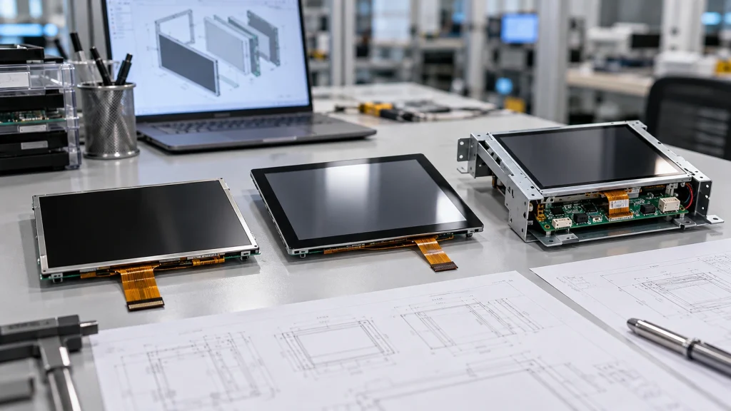
The short answer: buy a bare LCD/TFT module when your team owns the host electronics, touch, and mechanical integration; buy a touch display module when the enclosure and interface are already defined but you need an integrated front stack; choose a custom display assembly when the display must arrive with coordinated glass, bonding, FPCs, electronics, and mounting features. The right choice is the lowest integration level that still protects your product schedule and validation boundary.
That distinction matters because OEMs often compare products by diagonal size or resolution while leaving the real procurement boundary vague. A supplier may quote a panel, a complete touch module, or an application-ready assembly against the same sentence in an RFQ. Define what is included before comparing price, lead time, or risk. Start with Kadi Display’s industrial display range when you need to compare the available solution levels.
Start with the procurement boundary, not the screen size
Think of the display as a value chain rather than one part number. A bare TFT panel is the optical engine. A touch display module adds a touch sensor, cover glass, touch controller, or bonded front stack. A custom display assembly coordinates those layers with the electrical path and the mechanical installation. A modular HMI can go further by adding controller electronics and a defined enclosure interface.
|
Purchase level |
You receive |
Good fit when |
OEM still owns |
|
Bare TFT module |
LCD, backlight, FPC and panel electronics |
Host and enclosure are already designed |
Touch, carrier PCB, driver bring-up, mounting and validation |
|
Touch display module |
TFT plus touch, cover glass and agreed bonding |
You need a ready front interface |
Host interface, cable route, structure and system tests |
|
Custom display assembly |
Coordinated display stack, electronics, cables and mechanical items |
Geometry or integration is product-specific |
Host software, final certification and system approval unless agreed |
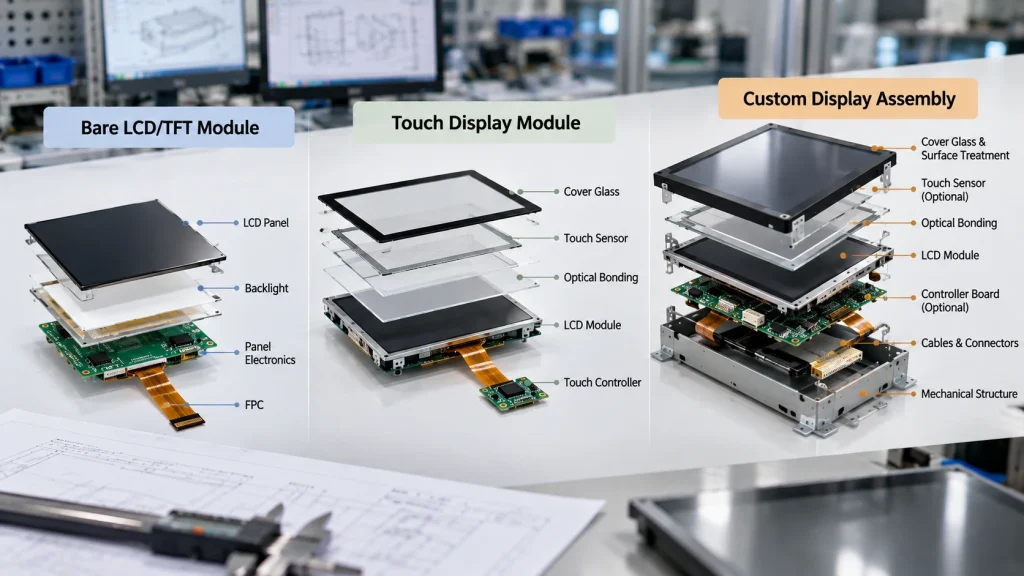
A useful reference is Kadi Display’s customized display solutions page, which describes project-based combinations of display, touch, cover glass, optical treatment, interfaces, controller boards, FPCs, cables, connectors, and mechanical parts. The quotation and approved drawing should define the exact boundary; a category description is not a substitute for project-specific acceptance criteria.
Choose a bare LCD or TFT module when your platform is already stable
A bare module is appropriate when your team has a clear host-board design, a known display interface, and the engineering capacity to own the remaining integration. This can be efficient for a controlled embedded product where the carrier PCB, power rails, backlight control, touch path, and enclosure are already frozen. It also preserves freedom to select a separate touch solution or a non-touch user interface.
Before ordering samples, confirm:
- the exact host output, connector, FPC pinout, contact direction, cable length, lane or pixel timing, and power/reset sequence;
- active area, outline, viewing direction, luminance under a stated condition, operating temperature, backlight control, and mechanical keep-outs;
- who supplies panel initialization, driver or firmware information, Device Tree data, and host-side bring-up support;
- how the panel will be supported in the enclosure so screws, gaskets, or cover pressure do not load the active area or chip-on-film region.
A module is not automatically a lower-risk purchase. It transfers more responsibility to the OEM. If the host, cable, or mounting design is still moving, the apparent part-cost saving can become integration work later.
Choose a touch display module when the front interface is the main requirement
A touch display module is the middle ground. It makes sense when the product needs a defined touch surface and cover glass, but the OEM can still handle the host board and final enclosure. The touch interface is commonly separate from video, often through I2C or USB, so specify the controller, interrupt, reset, address, firmware ownership, and cable path independently from the display link.
Treat cover glass, touch technology, and bonding as one front-stack decision. Capacitive and resistive touch suit different gloves, moisture, input methods, and environmental conditions. Optical bonding may reduce reflections and remove an air cavity, but the choice still depends on application light, condensation, impact, service policy, glass geometry, and the production process. Bonding by itself does not establish an ingress, impact, or environmental rating.
Kadi’s TFT-Touch Displays category shows the range of touch and interface combinations that may be evaluated. One public reference, the 10.1-inch 1280×800 CTP module, lists 1280×800 resolution, LVDS video, 800 nits brightness, a -20 to 70°C operating range, and an ILI2511 touch driver IC. Use such published values as a starting point only; the released configuration must follow the approved datasheet, drawing, sample, and BOM.
Choose a custom display assembly when the enclosure is part of the display specification
Move to a custom display assembly when the display cannot be treated as a drop-in rectangle. Typical triggers include a non-standard cutout, fixed mounting holes, a constrained FPC exit, a controller board that must sit behind the panel, a specified cover-glass artwork, optical treatment, a sealed front surface, or a cable route that must survive production assembly. In these cases, the display, touch, structure, and electronics must be released as one controlled stack.
Ask for one front-to-back stack drawing and one coordinate system. Freeze active area, component keep-outs, datums, gasket compression, support lands, connector access, FPC bend radius, grounding, and the allowable pressure on the viewing area. The supplier boundary should state exactly whether it includes the TFT, touch sensor, cover glass, bonding, controller or AD board, FPCs, cables, brackets, housing parts, and assembly instructions.
This is where a partner such as Kadi can be relevant: its public customization scope covers display and touch selection, optical treatment, interface and controller options, FPCs and cables, and mechanical parts. The OEM should still keep host-side software, final EMC or safety certification, environmental qualification, and system-level validation as explicit responsibility lines unless the project agreement says otherwise.
Make the decision by testing integration risk
The most useful selection test is not simply whether a connector mates. Check four compatibility layers in order, especially for MIPI DSI, LVDS, or a bridge architecture.
Physical connection
Verify connector pitch, pin numbering, contact side, lane or channel mapping, ground returns, cable length, bend path, power pins, reset pins, and available space. Physical mating proves only that parts can be connected.
Interface and signal behavior
Compare lane count, PHY capability, pixel format, timing, refresh rate, link bandwidth, LVDS mapping or HDMI direction, power rails, backlight control, and reset behavior. A matching label does not prove a matching electrical mode.
Driver and Device Tree support
Confirm the panel initialization sequence, Linux DRM or bridge path, Device Tree node or overlay, compatible string, regulator and GPIO names, backlight binding, touch driver, and maintenance owner. A panel can be electrically connected and still remain uninitialized.
Complete-system validation
Repeat cold boot, warm reboot, suspend/resume, brightness changes, touch use, temperature exposure, cable retention, and enclosure operation with the production-intent route and mounting pressure. Video and touch should be tested as separate paths, then together.
For a deeper embedded checklist, see Kadi’s MIPI DSI driver guide. It reinforces the difference between a physical interface label and a complete bring-up package.
What to include in the RFQ
Give the supplier enough information to quote the same integration boundary you intend to validate:
- application, host SoC/SBC or carrier board, operating system, BSP or kernel, and current driver status;
- display size, resolution, brightness condition, viewing distance, interface, lane/timing data, and pixel format;
- touch technology, controller, I2C or USB path, cover-glass drawing, coating, bonding preference, and input conditions;
- installation envelope, mounting holes, connector position, FPC route, cable length, power input, backlight control, and service access;
- temperature, humidity, vibration, cleaning, duty cycle, target quantity, project stage, schedule, and validation scope;
- existing sample, schematic, timing table, CAD, connector drawing, boot log, or fault photos when replacing a failed design.
This information reduces the chance that two quotes describe different products. It also creates a traceable path from sample evaluation to the production BOM.
Conclusion
Buy the lowest display level that your team can integrate and validate without leaving critical interfaces undefined. Choose a bare module when host electronics and mechanics are stable, a touch display module when the front stack is the missing piece, and a custom display assembly when glass, bonding, FPCs, controller electronics, and mounting geometry must be coordinated. The final decision should be based on evidence across physical, electrical, software, touch, and mechanical boundaries rather than on a connector name or resolution alone.
FAQs
Is a MIPI DSI label enough to prove compatibility?
No. Lane configuration, PHY behavior, timing, initialization, driver and Device Tree support, power sequencing, touch integration, and final-system validation still need to be checked.
Is a touch display module the same as a custom display assembly?
Not necessarily. A touch module can be a standard combination of TFT, touch, cover glass, and bonding. A custom assembly adds coordinated project-specific electrical, cable, structural, or housing requirements.
When should an OEM change the FPC instead of the display?
Change the FPC when the selected panel and interface are suitable but pinout, length, contact direction, connector position, or bend routing is wrong. Change the module when the interface or optical and mechanical envelope cannot be aligned.
What does Kadi need for a meaningful review?
Send the host platform, operating system, display size and resolution, interface and timing details, brightness, touch needs, temperature, mechanical drawing, installation space, quantities, schedule, and any existing sample or fault evidence.
Plan the next RFQ
If you are unsure which level to purchase, send the host platform, display size and resolution, interface, brightness, touch requirement, temperature range, installation drawing, quantity, schedule, and any fault photos through Kadi’s contact page. The goal is to confirm the integration boundary before a sample is treated as a production solution.
PREVIOUS
What to Ask an Industrial Display Manufacturer Before Design-In: Lifecycle, EOL, and Customization
NEXT
Industrial Display Obsolescence Management Plan Template: BOM, PCN, EOL, LTB, and Validation
Leave A Comment

Latest Blog & News
- What to Ask an Industrial Display Manufacturer Before Design-In: Lifecycle, EOL, and Customization
- LCD Display Module vs Custom Display Assembly: What Does an OEM Actually Need?
- Industrial Display Obsolescence Management Plan Template: BOM, PCN, EOL, LTB, and Validation
- How to Build Supply Chain Resilience for Long-Lifecycle Industrial Display Projects
- Last-Time Buy or LCD Replacement? A Decision Framework for Long-Lifecycle Display Projects