Home
-
Blog & News
-
MIPI DSI Display Driver Development for Embedded Linux What Hardware Buyers Need to Confirm
MIPI DSI Display Driver Development for Embedded Linux What Hardware Buyers Need to Confirm
2026-10-01
00:00
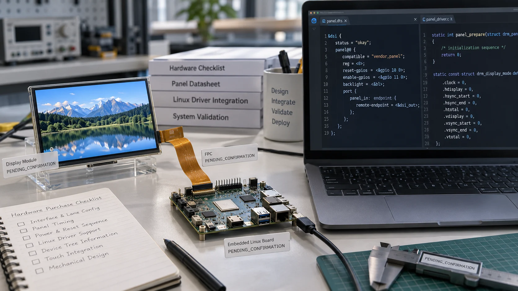
A MIPI DSI label on a display datasheet is only the starting point for an Embedded Linux integration. A production-ready design also needs a compatible PHY and lane configuration, complete panel timing, power and reset behavior, a usable kernel driver or initialization sequence, Device Tree information, touch integration, and mechanical evidence. Hardware buyers who confirm these items before ordering samples can avoid the common situation in which a panel works on a bench but fails after a kernel change, enclosure assembly, warm reboot, or production cable change. Start with Kadi’s embedded display solutions to compare the published interface and platform categories.
The four compatibility layers to confirm
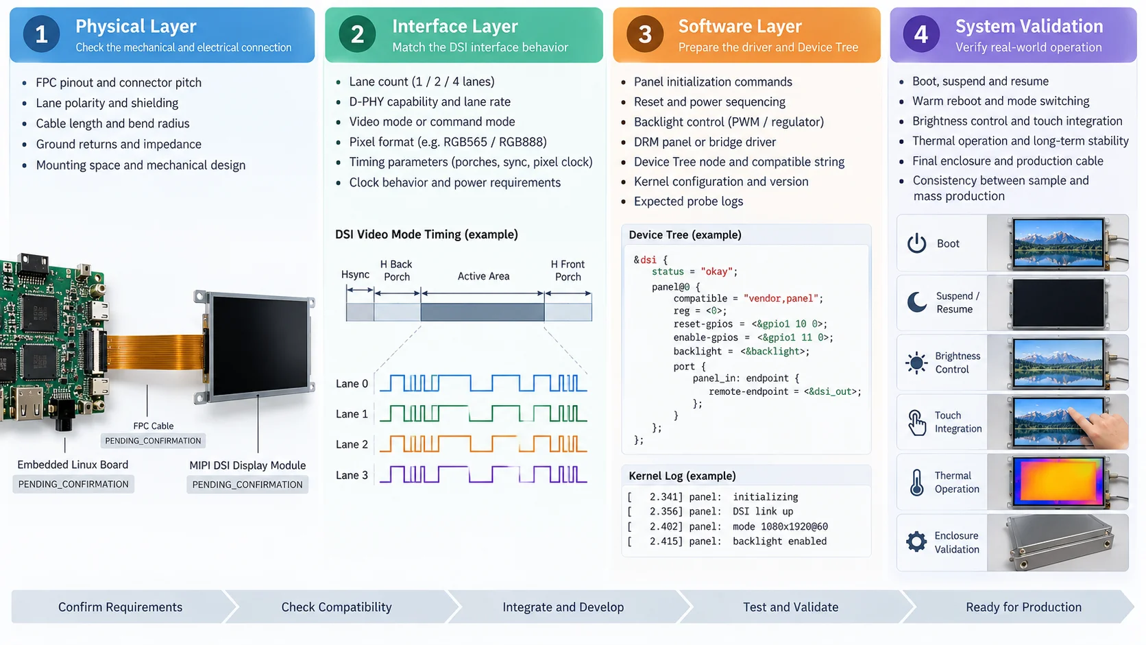
Treat MIPI DSI compatibility as four linked layers rather than a connector check. First is the physical path: FPC pinout, connector pitch, lane polarity, shielding, cable length, ground returns, and available mounting space. Second is the interface behavior: one, two, or four data lanes; D-PHY capability; video or command mode; pixel format; lane rate; clock behavior; and the exact timing values. Third is software support: panel initialization commands, reset and power sequencing, backlight control, Linux DRM or bridge integration, and Device Tree bindings. Fourth is system validation: boot, suspend and resume, warm reboot, refresh-rate changes, thermal operation, touch, brightness control, and the final enclosure.
This layered view aligns with how Linux represents display hardware. The kernel documentation describes Device Tree as a hardware description that avoids hard-coding machine details, while DRM provides panel, bridge, connector, mode-setting, and MIPI DSI helpers. In practice, a buyer should ask for the information needed to describe the panel accurately in the target board support package, not only for a cable drawing.
Confirm the host side before selecting a panel
Start with the exact host board, SoC or compute module, carrier board, Linux distribution, kernel version, bootloader, and display pipeline. An application processor may expose MIPI DSI but still impose limits on lane count, maximum lane rate, pixel formats, supported video modes, or bridge topology. A carrier board can also change the available connector, voltage rails, GPIO assignments, or backlight interface.
Ask the supplier to review the host documentation against the panel datasheet. The review should identify the DSI controller instance, clock and data-lane mapping, lane polarity, reset GPIO, enable GPIO, backlight PWM or regulator, I2C touch bus, and any bridge IC between the host and panel. If the proposed module is listed for a selected Toradex platform or Raspberry Pi CM4/CM5 carrier, treat that as a useful starting point, not a universal compatibility statement. The exact carrier, operating system, BSP, connector, timing, and mechanical design still need confirmation.
Request a complete panel and timing package
A buyer should receive more than resolution and brightness. Request the active area, horizontal and vertical porches, sync widths, pixel clock range, refresh-rate range, pixel format, lane count, DSI mode, video-mode type, command sequence, and permitted tolerances. Also request the panel controller or driver IC family, because two panels with the same resolution can require different initialization commands and timing constraints.
Check bandwidth with the intended format and refresh rate. RGB888 carries more payload than RGB565, and blanking intervals add to the required link budget. The host must sustain the selected mode without relying on an undocumented margin. If the supplier proposes a bridge, ask which side speaks DSI, which side drives the panel, how mode information is passed, and which party owns bridge configuration and validation. “MIPI compatible” is not enough evidence to close these questions.
Confirm FPC pin numbering, connector mating height, impedance guidance, ground pins, bend radius, cable length, and whether the production cable differs from the sample cable. A short bench cable can lose margin when routed around a metal bracket or near a noisy power converter.
Make the Linux driver deliverables explicit
For Embedded Linux, the driver conversation should be concrete. Ask whether the display uses an upstream or vendor kernel driver, a DRM panel driver, a bridge driver, a bootloader-only sequence, or a supplied patch. Confirm the target kernel branch, configuration symbols, Device Tree node or overlay, compatible string, initialization commands, reset delays, regulator names, GPIO polarity, backlight binding, and expected probe logs.
A useful acceptance test is a reproducible bring-up package: device-tree source, patch or overlay, panel command table, timing table, wiring diagram, and a short procedure that records kernel version, commit, dmesg output, mode, brightness, and touch status. If software ownership is split, write down who maintains host-side BSP changes and who supplies panel-specific updates. Kadi describes its scope as project-by-project and notes that host-side software, BSP work, certification, environmental testing, and final system validation require technical review and written agreement. That distinction should appear in the purchase specification.
Separate display video, touch, and power evidence
MIPI DSI normally carries display video. Touch commonly uses a separate I2C or USB path with its own controller, interrupt, reset, address, and firmware. Require independent evidence for image output, touch reporting, backlight dimming, and power sequencing. A bright image does not prove touch is configured, and responsive touch does not prove the DSI link is stable.
Confirm the panel-side rails, voltage tolerances, power-on order, reset timing, sleep and wake commands, and backlight enable behavior. Test cold boot, warm reboot, suspend and resume, repeated power cycles, and brightness changes. If the image disappears after warm-up, compare panel temperature, regulator temperature, backlight load, DSI error status, and enclosure conditions before replacing the module. Kadi’s troubleshooting guidance recommends separating image loss, backlight loss, touch behavior, host resets, and enclosure-only failures so the next measurement targets the right layer.
Validate the production mechanical and environmental path
The final display is a mechanical assembly, not a floating panel. Confirm outline dimensions, active-area position, mounting holes, bezel, cover glass, touch stack, bonding, connector access, FPC bend path, and service clearance. For outdoor or window-mounted products, evaluate brightness, reflections, thermal transfer, and sealing as a system. Do not convert a listed temperature range into a guaranteed enclosure result without testing the assembled device.
For example, Kadi’s KD101WXDSI01 listing identifies a 10.1-inch 1280×800 MIPI DSI touch module with 1000-nit brightness, I2C capacitive touch, optical bonding, and a stated -20°C to +70°C operating range for the listed configuration. Those are useful selection inputs. The approved datasheet, drawing, sample, and production bill of materials must still control the released design.
A buyer-ready confirmation checklist
Before approving a sample, collect these answers in one evidence package:
– Host platform: exact board, SoC, carrier, Linux distribution, kernel and bootloader.
– Video path: DSI controller, lane count, lane rate, mode, pixel format, timing and refresh range.
– Panel data: controller IC, initialization sequence, reset delays, rails, backlight and allowed tolerances.
– Physical path: connector, pinout, FPC drawing, cable length, bend limits, shielding and mounting.
– Touch path: controller, I2C or USB wiring, interrupt, reset, address and firmware responsibility.
– Software package: driver or patch, Device Tree, configuration symbols, logs and maintenance owner.
– Validation: cold and warm boot, suspend/resume, brightness, touch, thermal, enclosure and repeated-cycle results.
Choosing the right Kadi engagement level
A standard module may be sufficient when the host, timing, connector, touch path, and enclosure already match. A modified module can address an FPC, cover-glass, brightness, cable, or mounting requirement. A custom display assembly is more appropriate when the project needs coordinated touch, optical bonding, housing, interface adaptation, or a production drawing. Kadi presents these options across its embedded solution, Raspberry Pi display, and customized display categories; the correct level depends on the evidence package and the integration boundary agreed for the project.
When requesting a quote, send the host platform, operating system and kernel, display size and resolution, DSI lane and timing information, brightness, touch interface, temperature, mechanical drawing, application, sample quantity, target quantity, and any fault photos or existing samples. You can review the 10.1-inch MIPI DSI touch module as a concrete reference, compare the Raspberry Pi display category, read the MIPI DSI industrial display guide, and use the contact page to define open technical questions before sampling.
Conclusion
Successful MIPI DSI development on Embedded Linux is a chain of evidence: host capability, physical interconnect, timing and lane behavior, driver and Device Tree support, power and touch separation, and final-system validation. Hardware buyers who make each layer explicit can compare modules on integration risk instead of connector labels. Kadi Display can support the path from a display module to a project-specific assembly when the host, mechanical, software, and validation boundaries are documented and reviewed.
FAQs
Is a MIPI DSI display plug-and-play on Linux?
Not necessarily. Plug-and-play depends on the exact host, connector, lane and timing configuration, power and reset wiring, driver or Device Tree support, and touch path.
What driver files should a supplier provide?
Request the panel driver or patch, Device Tree node or overlay, initialization commands, timing table, configuration requirements, wiring information, and a reproducible bring-up procedure.
Can the same display work on Raspberry Pi and another Linux SBC?
It may, but compatibility must be checked for each carrier, DSI controller, lane mapping, timing, BSP, connector, power design, and mechanical installation.
Should touch be included in the MIPI DSI driver scope?
Treat touch as a separate path unless the approved design explicitly combines responsibilities. Confirm its I2C or USB interface, interrupt, reset, address, firmware, and validation separately.
What should be sent for a reliable RFQ?
Send the host platform, OS and kernel, display requirements, DSI timing and connector data, touch needs, mechanical drawing, environment, application, quantities, schedule, and any existing fault evidence.
Leave A Comment

Latest Blog & News
- MIPI DSI Display Driver Development for Embedded Linux What Hardware Buyers Need to Confirm
- IP65 vs IP67 Industrial Displays: What the Rating Actually Covers
- How to Specify a Touchscreen for Food-Processing Equipment
- Thermal Management for High Brightness LCDs in Sealed Outdoor Enclosures
- 4 Wire vs 5 Wire Resistive Touchscreens for Industrial Equipment
Related Blog & News