




Home
-
Blog & News
-
How to Develop a Production Ready Custom Display Assembly TFT Module Touch Cover Glass FPC Bonding and Mounting
How to Develop a Production Ready Custom Display Assembly TFT Module Touch Cover Glass FPC Bonding and Mounting
2026-10-16
00:00
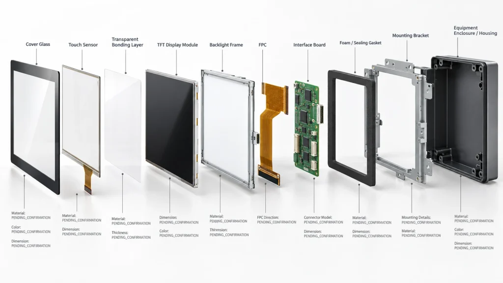
A production-ready custom display assembly is a controlled stack, not a collection of individually acceptable parts. The TFT module, touch sensor, cover glass, bonding layer, FPC, connector, bracket, gasket, and enclosure must share approved interfaces, datums, tolerances, and validation evidence. OEM teams should define the complete delivered assembly and its ownership boundary before selecting a panel. This approach prevents late changes in glass tooling, cable routing, touch tuning, and mounting pressure from invalidating a successful prototype. Kadi Display supports this project path from display and touch selection through agreed mechanical and electrical integration.
Define the assembly and release boundary
Start by naming what the supplier will deliver. It may be a TFT module, a touch display module, a bonded display stack, an assembly with controller board and cables, or an open-frame unit ready for the equipment enclosure. Each level changes the drawings, BOM ownership, incoming inspection, software responsibility, and failure analysis path. If these boundaries remain vague, two suppliers can quote different products against the same request.
Freeze the application, host platform, interface, size, resolution, viewing distance, ambient light, temperature, humidity, vibration, cleaning method, duty cycle, expected touch use, installation space, service strategy, and production plan. Mark hard requirements separately from targets. Also state who owns host software, certifications, environmental qualification, and final system validation. Kadi’s public customization scope covers agreed display hardware and project items; host-side BSP changes and final system approvals remain subject to project review.
Control the complete display stack
Build one front-to-back stack drawing and one controlled coordinate system. Kadi’s industrial display stack-up design guide explains why the active area, component keep-outs, compression zones, FPC service path, grounding interfaces, and enclosure datums must be managed together. The release package should show the following controls.
|
Assembly element |
Design decisions |
Release evidence |
|
TFT module |
Size, active area, brightness, viewing, interface, temperature |
Approved datasheet and 2D drawing |
|
Touch and cover glass |
Technology, controller, lens geometry, ink, coating, use conditions |
Sensor and lens drawings plus touch test |
|
Bonding |
Air gap, OCA, or OCR; bond line, edge seal, cosmetic limits |
Process specification and inspection criteria |
|
FPC and electronics |
Pinout, pitch, contact side, bend path, power, grounding |
Cable drawing, schematic, and interface files |
|
Mounting |
Datums, supports, gasket compression, fasteners, service access |
Assembly drawing and tolerance analysis |
Select the TFT module and electrical path as a system
Choose the TFT against operating conditions rather than diagonal size alone. Confirm active area, outline, resolution, viewing direction, luminance under a stated condition, contrast, color requirements, polarizer, operating temperature, backlight life assumptions, interface, timing, supply rails, reset behavior, and backlight control. A panel with the correct resolution can still fail the project because its FPC exits into a wall, its active area is off-center, or its driver and timing are not supported by the host.
The host review must include the connector and pin mapping, cable length, interface mode, power sequence, initialization, driver or firmware, and final PCB location. Treat video, touch, and backlight as separate paths even when they share one FPC. Any change to the panel, controller board, cable, or PCB origin should trigger a review of timing, power, grounding, signal integrity, and mechanical reach.
Engineer touch and cover glass together
Select capacitive or resistive touch from the operator, environment, and input method. For capacitive touch, define touch points, controller, I2C or USB path, interrupt and reset, gloves, water behavior, palm rejection, accuracy, edge response, noise sources, display rotation, and firmware ownership. Validate the production-intent stack near the final display cable, power converter, metal bezel, and grounded enclosure because those conditions can change touch performance.
The cover glass drawing should control overall size, thickness, edge finish, corner radii, holes, cutouts, black mask, logo or printing, coating, surface hardness target, cosmetic zones, and bonding datum. Keep conductive ink and metal structures within the touch supplier’s permitted zones. Define how impact and finger loads move into the enclosure so the cover does not press the LCD active area or chip-on-film region.
[Product image placeholder: approved Kadi KD101WXHD05 assembly image showing the TFT, capacitive touch, OCA-bonded front stack, interface board, and four confirmed M3 mounting points.]
Choose bonding around real failure modes
Air bonding can suit controlled indoor lighting, cost-sensitive builds, and assemblies that require easier separation. Optical bonding with OCA or OCR can reduce internal reflections and remove the air cavity at the bonded interface, while coupling the front stack more closely. The choice should follow ambient light, condensation risk, vibration, impact, service policy, glass geometry, process capability, yield, and lifecycle cost. Kadi’s optical bonding versus air bonding guide provides a detailed selection framework. Bonding alone does not establish impact, ingress, or environmental ratings; those claims require assembly-level tests.
Release the adhesive family, nominal bond line, cure or lamination process, edge condition, alignment tolerance, bubble and particle limits, cosmetic zones, rework rule, and traceability fields. Test the bonded stack at the intended temperature range and mounting pressure. Bubbles, delamination, yellowing, touch drift, light leakage, or pressure mura must have written acceptance criteria rather than a visual judgment made after pilot production.
Design FPC cables and connectors for production
An FPC is both an electrical interface and an assembly component. Specify pin count, pitch, pin 1, top- or bottom-contact connector, same-side or opposite-side contacts, copper thickness, stiffener, exposed length, insertion depth, impedance needs, shielding or ground allocation, bend radius, cable exit, and strain relief. Confirm that the connector lock can be reached with production tools and inspected after assembly.
Model the cable in installed and service positions. Keep bends away from stiffener transitions, avoid twisting the flex, and prevent foam, screws, or housing edges from loading it. A passive FPC can rearrange compatible signals, but it cannot create a missing interface, correct an unsuitable voltage, or replace panel driver work. Freeze the cable drawing and mating connector in the production BOM.
Make the mounting structure protect the display
Use a common XY datum for the LCD, touch sensor, cover glass, PCB, bracket, and enclosure, then build a Z-direction tolerance stack. Separate the viewing-area center from the module outline because they may not be concentric. Define support lands, no-pressure zones, gasket width and working compression, fastener sequence, allowable enclosure flatness, connector clearance, adhesive thickness, and thermal expansion. Loads should pass into the frame or dedicated supports rather than through the active display area.
The KD101WXHD05 integrated touch display illustrates a higher integration level with a 10.1-inch 1280 x 800 TFT, capacitive touch, OCA bonding, HDMI and Type-C video, USB touch, and four M3 mounting points. It is a useful reference for discussing boundaries, but the released OEM assembly must still follow its approved drawing, configuration, sample, and BOM.
Validate production intent samples and freeze the evidence
A prototype proves that one build can work. Production release requires repeatable parts, processes, and acceptance criteria. Test image quality, touch accuracy, brightness control, power cycles, warm reboot, suspend and resume, cable retention, connector access, pressure marks, temperature, humidity or condensation, vibration or shock, cleaning exposure, and enclosure operation at application-specific severities. Record the sample configuration and test fixture so later results remain comparable.
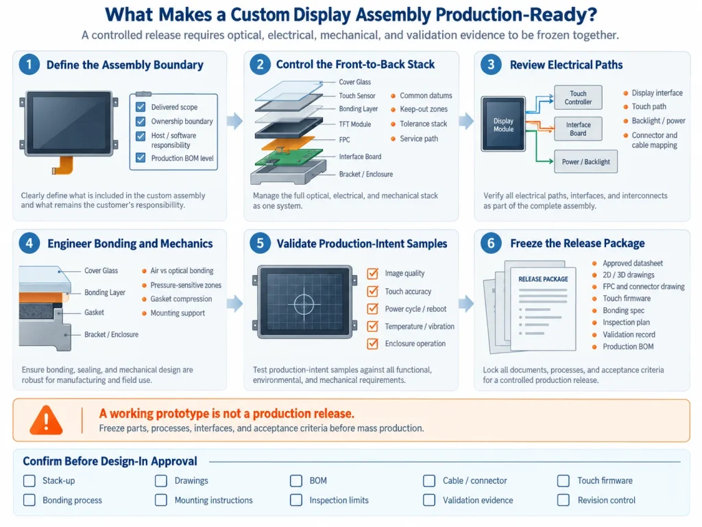
Before design-in approval, freeze the datasheet, drawings, stack-up, cover-glass artwork, FPC drawing, connector list, schematic, interface files, touch firmware, bonding specification, mounting instructions, cosmetic standard, inspection plan, deviations, revision rules, and production BOM. Pilot units should use production materials and tooling so yield, assembly time, and inspection limits can be assessed before release.
What to send for a custom display assembly
Kadi’s customized display solutions cover project-based combinations of display, touch, cover glass, optical treatment, interfaces, controller boards, FPCs, cables, connectors, and mechanical parts. For an effective review, send the application, host and operating system, size and resolution, interface, brightness condition, temperature range, touch requirements, cover-glass drawing, installation space, power input, target quantities, schedule, enclosure CAD, connector data, and available samples or schematics.
Conclusion
A custom display assembly becomes production-ready when its optical, electrical, mechanical, software, and manufacturing interfaces are released as one controlled system. Freeze the boundary, manage the stack, validate production-intent samples, and approve the evidence before locking the BOM. OEM teams can submit host details, drawings, environmental requirements, touch and bonding needs, installation space, quantities, and schedule through Kadi’s contact page for project-specific evaluation.
FAQs
What is included in a custom display assembly?
The scope can range from a TFT and touch module to a bonded stack with cover glass, FPCs, controller board, cables, bracket, and agreed housing parts. The quotation and approved drawing should define the exact boundary.
Should the TFT or enclosure be selected first?
Select them together while requirements remain flexible. Freeze the display drawing and realistic alternatives before the industrial design envelope, connector access, and mounting scheme are approved.
When should an OEM use optical bonding?
Use it when reduced internal reflections, elimination of the bonded-interface air cavity, or closer mechanical coupling addresses a defined requirement. Confirm the choice through complete-stack environmental and optical tests.
Why does a display pass bench testing but fail after mounting?
The enclosure may add pressure, grounding changes, touch noise, cable strain, thermal load, or gasket compression that was absent on the bench. Test the production-intent assembly in its final mounting condition.
What must be frozen before mass production?
Freeze the approved drawings, BOM, interface files, touch firmware, bonding process, mounting instructions, inspection limits, validation record, deviations, and change-approval rules.
Leave A Comment

Latest Blog & News
- How to Develop a Production Ready Custom Display Assembly TFT Module Touch Cover Glass FPC Bonding and Mounting
- 15 Pin vs 22 Pin Raspberry Pi DSI Connectors Cable Pinout and Compatibility
- Native MIPI DSI vs LVDS or HDMI Bridge: An OEM Display Architecture Decision Guide
- MIPI DSI Display Driver Development for Embedded Linux What Hardware Buyers Need to Confirm
- Anti-Glare Glass Haze and Sparkle on High-PPI Displays: A Sample Evaluation Guide

