




Startseite
-
Blog & Neuigkeiten
-
Von Innenräumen bis zu extremen Umgebungen: Ein spektrumbasierter Entscheidungsrahmen für die Helligkeit industrieller Displays
Von Innenräumen bis zu extremen Umgebungen: Ein spektrumbasierter Entscheidungsrahmen für die Helligkeit industrieller Displays
2026-05-13
11:48
Von Innenräumen bis hin zu extremen Umgebungen:
Ein spektrumbasierter Entscheidungsrahmen für die Helligkeit industrieller Displays
Die richtige Wahl zwischen 400 Nits, 1000 Nits und 2000 Nits – mit den physikalischen Grundlagen dazu
Industrielle Anzeige Technologie
Warum die Helligkeitsauswahl ein Spektrumproblem und keine binäre Entscheidung ist
Der Begriff „Außendisplay“ umfasst ein breites Spektrum an realen Bedingungen. Ein Fahrkartenautomat unter einem Vordach an einem großen Bahnhof ist an einem hellen Nachmittag etwa 5.000–8.000 Lux ausgesetzt. Ein Bodenfeuchtemessgerät, das an einem Pfosten auf einem offenen Feld in Zentralaustralien befestigt ist, erlebt im Hochsommer 80.000–100.000 Lux. Beide befinden sich im Freien. Beide benötigen ein „sonnenlichttaugliches Display“. Doch die Anforderungen an die Helligkeit – und die damit verbundenen thermischen, Energieverbrauchs- und Kostenfolgen – sind völlig unterschiedlich.
Die Industrie für industrielle Displays neigt dazu, diese Unterscheidungen auf drei Bezugspunkte zu reduzieren: 400 Nits für Innenräume, 1.000 Nits für Außenbereiche und 2.000 Nits für anspruchsvolle Außenbedingungen. Diese Werte sind zwar nützliche Richtwerte, aber als Endpunkte problematisch. Werden sie als starre Kategorien anstatt als Positionen auf einem kontinuierlichen Spektrum betrachtet, führt dies zu zwei gleichermaßen negativen Ergebnissen: Überdimensionierung, die die thermische Komplexität erhöht und die Lebensdauer der Hintergrundbeleuchtung verkürzt, und Unterdimensionierung, die in realen Einsatzbedingungen, die in der Laborprüfung nie simuliert wurden, zu einem unlesbaren Display führt.
Das in diesem Artikel vorgestellte Rahmenwerk betrachtet Helligkeit als spektrale Entscheidung – ausgehend von gemessenen Umgebungsbedingungen, unter Berücksichtigung der optischen Physik und der Wechselwirkungen mit Oberflächenbehandlungen, um schließlich einen Helligkeitswert zu ermitteln, der optimal auf die jeweilige Anwendung abgestimmt ist. Die Checkliste mit sieben Fragen am Ende lässt sich für jedes beliebige Einsatzszenario in weniger als zwanzig Minuten ausfüllen.
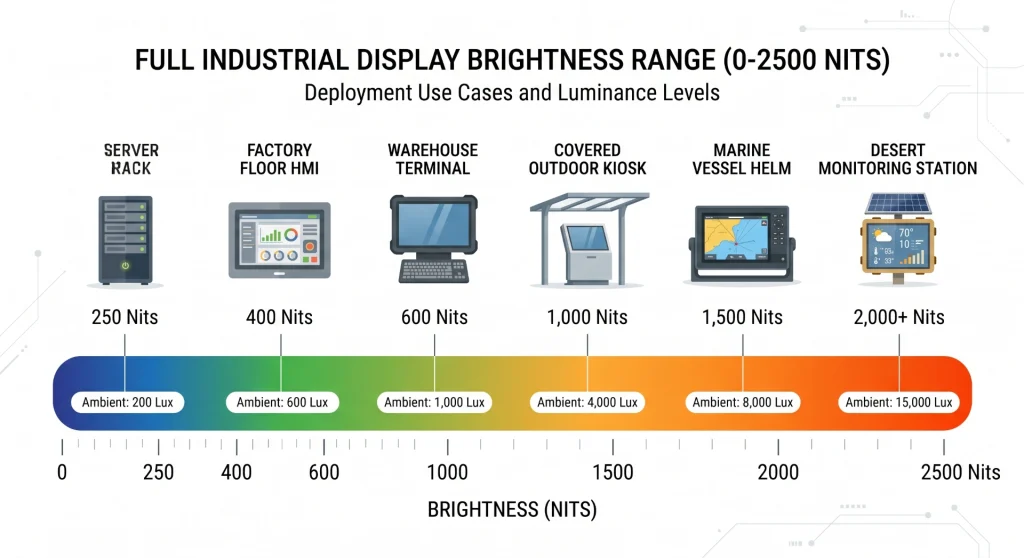
Physikalische Erklärung: Die Helligkeit eines Displays (in Nits) gibt an, wie viel Licht es abgibt. Die Umgebungshelligkeit (in Lux) gibt an, wie viel Licht auf seine Oberfläche fällt. Die Lesbarkeit hängt vom Verhältnis zwischen der vom Display abgegebenen und der von der Umgebung reflektierten Helligkeit ab – dem effektiven Kontrastverhältnis (ECR). Das ECR ist der Wert, der letztendlich darüber entscheidet, ob ein Benutzer den Bildschirm lesen kann.
Die Physik des effektiven Kontrastverhältnisses – Warum Details allein die halbe Wahrheit erzählen
Die ECR-Formel, die jeder Spezifizierer kennen sollte
Die Effektives Kontrastverhältnis (ECR) Der ECR quantifiziert die Lesbarkeit im Alltag. Die vereinfachte Formel lautet: ECR = (L_Panel + L_Reflect) / (L_Black + L_Reflect), wobei L_Panel die Weißleuchtdichte des Panels (annähernd die Helligkeit in cd/m²) ist, L_Black die Dunkelleuchtdichte (ca. 0,1–0,5 % von Weiß) und L_Reflect das vom Display reflektierte Umgebungslicht. Reflektierte Leuchtdichte: L_Reflect = E_Umgebung × R / π, wobei E_Umgebung die Umgebungsbeleuchtungsstärke in Lux und R der Oberflächenreflexionsgrad (dimensionslos) ist.
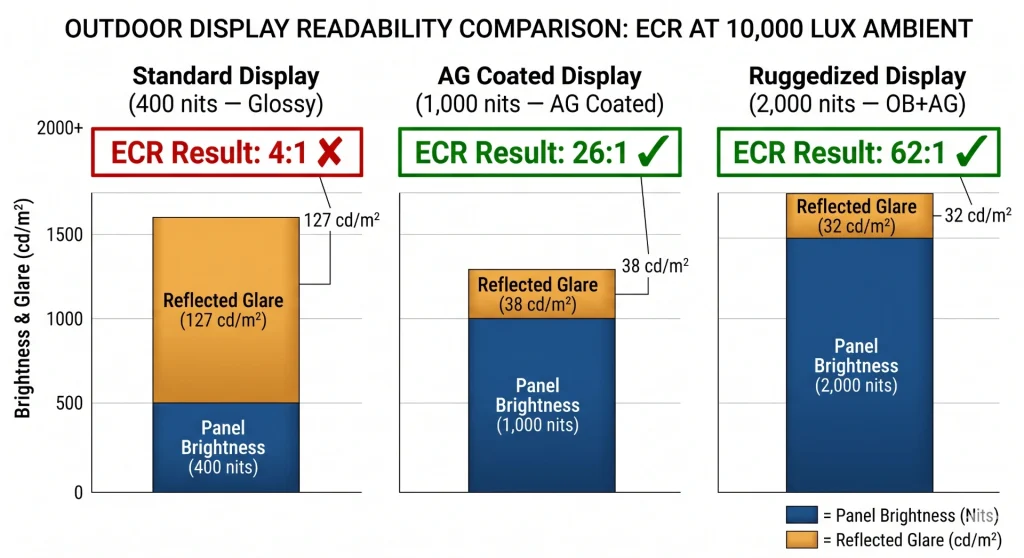
Beispielrechnung: 10.000 Lux Umgebungslicht, glänzende Oberfläche mit 4 % Reflexionsgrad, 400 cd/m² Displayhelligkeit. L_reflect = 10.000 × 0,04 / π ≈ 127 cd/m². ECR ≈ (400 + 127) / (0,5 + 127) ≈ 4.1:1Das ist kaum lesbar – die praktische Komfortschwelle liegt bei 5:1. Gleiches Szenario, 1000-Nit-Panel: ECR ≈ 8.8:1Gut lesbar. Gleiches Szenario mit 1000 cd/m² UND optischer Verklebung + AG, wodurch R auf 1 % reduziert wird: L_reflect ≈ 32 cd/m². ECR ≈ 31.8:1Ausgezeichnet. Die Oberflächenbehandlung hat die Helligkeit mehr als verdoppelt.
Der Oberflächenbehandlungs-Multiplikator
Eine Reduzierung des Reflexionsgrades von 4 % auf 1 % bei einer Umgebungsbeleuchtungsstärke von 10.000 Lux hat eine Größerer Effekt auf den ECR als eine Verdopplung der Helligkeit von 400 auf 800 Nits bei gleichem Reflexionsgrad. Aus diesem Grund prüfen erfahrene Display-Systemingenieure optische Verklebung und AG-Beschichtung, bevor sie zu Panels mit höherer Helligkeit greifen – dies ist fast immer kostengünstiger, sowohl hinsichtlich des Panelpreises als auch des Wärmemanagements. Die daraus resultierende technische Regel lautet: In Umgebungen mit hohem Umgebungslicht entspricht eine Halbierung des Reflexionsgrades in etwa einer Verdopplung der Helligkeit.
Ein 1000-Nit-Panel mit optischer Verklebung und AG-Beschichtung bei 1 % effektivem Reflexionsgrad ist einem 2000-Nit-Glanzpanel bei direkter Sonneneinstrahlung von 50.000 Lux überlegen. Bei 1 % Reflexionsgrad: L_reflect ≈ 159 cd/m², ECR ≈ 6,3:1. Bei 4 % Reflexionsgrad und 2000 Nits: L_reflect ≈ 637 cd/m², ECR ≈ 3,1:1. Das Panel mit der niedrigeren Helligkeit ist bei entsprechender Behandlung besser lesbar.
Das Helligkeitsspektrum – Sechs Zonen vom dunklen Zimmer bis zur Wüste
Die folgende Tabelle definiert sechs Einsatzzonen basierend auf der Umgebungsbeleuchtungsstärke und den damit erzielbaren effektiven Kontrastverhältnissen bei verschiedenen Helligkeits- und Oberflächenbehandlungskombinationen. Mit ✔ gekennzeichnete ECR-Werte überschreiten den praktischen Lesbarkeitsschwellenwert von 5:1; ✗ bedeutet, dass sie darunter liegen.
Helligkeitsspektrum industrieller Displays – Sechs Einsatzzonen
* Der ECR-Wert liegt an der oberen Lux-Grenze jeder Zone und basiert auf einer standardmäßigen Glanzreflexion von 4 %, sofern keine optische Verklebung und AG spezifiziert sind. Der tatsächliche ECR-Wert variiert je nach Oberflächenbehandlung und Einbaugeometrie.
Die sogenannte Übergangszone ist der Bereich, in dem die meisten Entscheidungen bezüglich industrieller Displays scheitern. Anwendungen in überdachten Außenbereichen, halboffenen Lagerhallen, Laderampen und Fahrzeuginnenräumen fallen in diesen Bereich – ein 400-Nit-Panel, das in einer Fabrikhalle einwandfrei funktioniert, versagt hier, während ein 2000-Nit-Panel unnötige thermische Belastung und Kosten verursacht. Die 1000-Nit-Variante mit optischer Verklebung ist die optimale technische Lösung für die meisten Anwendungen in der Übergangszone.
Zonenweise Analyse – Anpassung der Helligkeit an die Umgebung
Zonen 1 und 2: Industrielle Innenräume (250–600 Nits)
Kontrollräume, Laborgeräte, Server-Management-Terminals und HMI-Panels in der Produktionshalle, die sich innerhalb der Gebäudehülle befinden, liegen in den Zonen 1 und 2. Die Umgebungsbeleuchtungsstärke in diesen Bereichen reicht von etwa 200 Lux in schwach beleuchteten Maschinenräumen bis zu 1.000 Lux unter hochintensiver LED-Fabrikbeleuchtung. Bei diesen Umgebungsbeleuchtungsstärken erzielt ein 400-Nit-IPS-TFT-Panel ECR-Werte deutlich über 20:1.
Weniger offensichtlich ist, dass Eine zu hohe Helligkeit in Zone 1 und 2 führt zu einem echten Ergonomieproblem.Bediener, die 8- bis 12-Stunden-Schichten in einer Umgebung mit 300 Lux vor einem 1000-Nit-Display absolvieren, sehen eine Oberflächenhelligkeit, die in etwa einem hellen, bewölkten Himmel entspricht. Augenermüdung, Kopfschmerzen und verminderte Konzentrationsfähigkeit sind dokumentierte Folgen von anhaltender Betrachtung hoher Helligkeit in Umgebungen mit geringer Umgebungshelligkeit. Ein korrekt dimensioniertes 400-Nit-Panel sorgt in dieser Umgebung dafür, dass sich das Sehsystem des Bedieners während der gesamten Schicht angenehm anpasst.
Zone 3: Die Übergangszone (600–1.000 Nits) – Die am meisten unterschätzte Lichtstärke
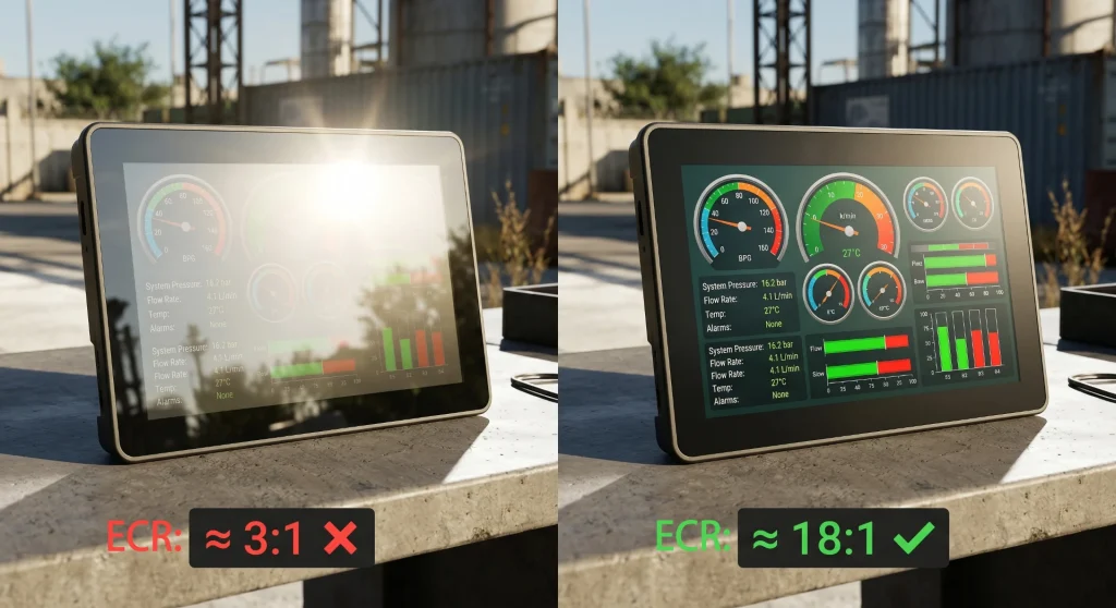
Die Übergangszone umfasst Laderampen in Lagerhallen, überdachte Tankstellenvorplätze, Fahrzeuginnenräume, Fahrerkabinen von Landmaschinen und Baustellenbürocontainer. Die Umgebungsbeleuchtungsstärke schwankt: An einer überdachten Laderampe können morgens 500 Lux und nachmittags, wenn die Sonne direkt durch ein offenes Tor scheint, 8.000 Lux gemessen werden. Für Anwendungen in Zone 3 ist die richtige Antwort fast immer 1.000 cd/m² mit optischer Verklebung und AG-BeschichtungStatt 400 oder 2.000 Nits. Bei 1 % effektiver Reflexion beträgt das ECR bei 8.000 Lux etwa 18:1. Das glänzende Panel mit 400 Nits im selben Szenario: ECR ≈ 4:1. Unlesbar.
Relevantes Produkt: 10,1 Zoll (25,7 cm) industrielles HDMI-Touchdisplay mit 1.500 cd/m² Helligkeit – Kadi Display — Auflösung von 1200 × 1920 Pixeln, konzipiert für Ladestationen für Elektrofahrzeuge, Außenkioske und Installationen im halböffentlichen Bereich. HDMI-Schnittstelle, optionaler PCAP-Touchscreen.
Zonen 4 und 5: Echte Außenbeleuchtung (1.000–2.000 cd/m²)
Sobald das Display im Freien eingesetzt wird – beispielsweise in offenen Verkehrsterminals, an Geldautomaten im Freien, an Steuerständen von Schiffen oder an Informationstafeln am Straßenrand –, verschiebt sich die Mindesthelligkeitsschwelle deutlich auf 1.000 Nits. Bei Werten zwischen 1.000 und 2.000 Nits hängt die Auswahl von folgenden Faktoren ab: der ungünstigste Sonnenwinkel, dem natürlichen Beschattungsgrad der Anlage und dem Wärmebudget des Gehäuses.
Anwendungen auf See sind mit einer Kombination aus direkter Sonneneinstrahlung, starker Himmelsreflexion an der Wasseroberfläche (wodurch die effektive Umgebungsbeleuchtung über die direkte Sonneneinstrahlung hinaus erhöht wird) und Salznebel konfrontiert, der eine Kühlung durch offene Belüftung ausschließt. Steuerstanddisplays mit 2.000 cd/m² und optischer Verklebung sind fast immer die richtige Wahl – das Wärmemanagement muss jedoch von Anfang an in die Planung einbezogen und darf nicht erst im Nachhinein berücksichtigt werden.
Zone 6: Extreme Umgebungen – Wo Standardregeln versagen
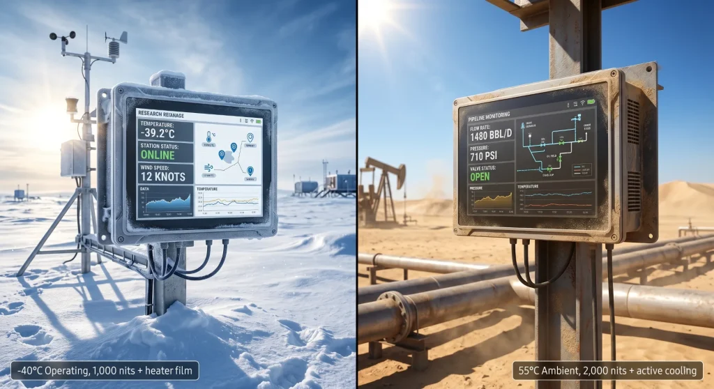
Polarstationen, meteorologische Geräte in großer Höhe, Überwachungsstationen in der Wüste und Displays von Militärfahrzeugen überschreiten die 2000-Nit-Basislinie – aber in diesen Umgebungen Die Helligkeit allein ist nicht der begrenzende Faktor.Temperaturen unter −30 °C verhindern das Schalten von Standard-LCD-Flüssigkristallen ohne Heizfolie. Die Displayspezifikation für extreme Umgebungen muss daher mit dem Temperaturprofil und nicht mit den Helligkeitsanforderungen beginnen.
Bei Einsätzen in Polargebieten ist die Umgebungsbeleuchtungsstärke typischerweise moderat (10.000–25.000 Lux im Sommermaximum), sodass 1.000–1.500 cd/m² mit optischer Verklebung in der Regel für die Lesbarkeit ausreichen. Die technische Herausforderung besteht im Kaltstart: die Spezifizierung einer Heizfolie hinter der LCD-Schicht Bei LCD-Displays ist ein breiter Temperaturbereich wichtiger als eine höhere Helligkeit. In Wüstenregionen kehrt sich die Priorität um: Hier sind 1.500–2.000 Nits entscheidend, und Beschattungsstrukturen oder aktive Kühlung sind wichtiger als die genaue Helligkeitszahl über 1.500 Nits.
ECR-Anwendungsbeispiele – Die Zahlen auswerten
Die folgende Tabelle veranschaulicht anhand der ECR-Formel acht reale Szenarien. Sie zeigt deutlich, welche Helligkeitsstufe erforderlich ist und wie stark die Oberflächenbehandlung das Ergebnis beeinflusst.
ECR-Anwendungsbeispiele – Acht industrielle Einsatzszenarien
ECR-Formel: (Panel-Nits + L_reflektieren) / (Schwarzpegel + L_reflektieren). L_reflektieren = Umgebungslichtstärke × Reflexionsgrad / π. Der Schwarzwert des Panels wird mit 0,2 cd/m² angenommen.
Die Zeile „Direkte Sommersonne, 2.000 cd/m², OB+AG“ überrascht die meisten Ingenieure. Dass 2.000 cd/m² bei 60.000 Lux direkter Sonneneinstrahlung überhaupt funktionieren, liegt allein an der Oberflächenbehandlung, die den Reflexionsgrad auf 1 % reduziert. Ohne diese Behandlung (4 % Reflexionsgrad) erreicht dasselbe 2.000-cd/m²-Panel nur ein ECR von ca. 2,6:1 – schlechter als ein 1.000-cd/m²-Panel mit OB+AG. Dies ist die Grundlage für die Ingenieursregel: Vor einer Erhöhung der cd/m²-Zahl sollte immer eine Oberflächenbehandlung spezifiziert werden.
Technische Referenz: Sonnenlichttaugliche Displays – Wichtige Parameter – Kadi-Display — Detaillierte Betrachtung von ECR, optischer Verklebung, AR/AG-Beschichtungen und Spezifikationen für einen breiten Temperaturbereich bei der Auswahl von LCDs für den Außenbereich.
Adaptives Dimmen – Warum Peak Nits nicht Operating Nits ist
Lebensdauer der Hintergrundbeleuchtung und die Realität des Tastverhältnisses
Ein 2000-Nit-Display, das kontinuierlich mit 2000 Nits betrieben wird, ist Lebensdauer der T70-Hintergrundbeleuchtung Die Werte liegen typischerweise im Bereich von 15.000–25.000 Stunden – das entspricht 2,6–4,3 Jahren, bevor die Lichtleistung auf 70 % der Anfangshelligkeit abfällt. Bei einem Produkt mit einer geplanten Lebensdauer von 7–10 Jahren ist mindestens ein Austausch der Hintergrundbeleuchtung im Wartungsplan vorgesehen, unabhängig davon, ob dies explizit erwähnt wird oder nicht.
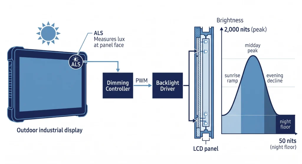
Adaptives Dimmen verändert diese Berechnung erheblich. Ein 2000-Nit-Außendisplay, das bei schwachem Licht auf 800 Nits und nachts auf 400 Nits reduziert wird und im Durchschnitt über einen 16-Stunden-Tag etwa 1000 Nits erreicht, hat eine LED-Sperrschichttemperatur, die in etwa der eines Displays mit fester Helligkeit von 1000 Nits entspricht. Die Lebensdauer des T70 kann bei diesem Betriebszyklus auf 35.000–50.000 Stunden verlängert werden. — Erreichen des 7- bis 10-Jahres-Ziels ohne Austausch der Hintergrundbeleuchtung.
Implementierung: ALS, PWM und die Nachtschichtanforderung
Adaptives Dimmen erfordert drei Hardware-Elemente: ein Umgebungslichtsensor (ALS) an der Vorderseite der Platte, ein PWM-gesteuerter Hintergrundbeleuchtungstreiber mit stufenloser Dimmung über den gesamten Bereich und Firmware-Logik, die den ALS-Messwert dem Zielwert in Nits zuordnet. Zwei Spezifikationsdetails sind wichtig und werden häufig übersehen. Erstens: PWM-FrequenzUnterhalb von 1.000 Hz ist das Hintergrundbeleuchtungsflimmern bei längerem Betrachten im peripheren Sichtfeld wahrnehmbar – geben Sie daher mindestens 1.000 Hz an. Zweitens: MindestdimmungFür Anwendungen im Dunkeln auf 50–100 Nits einstellen.
Sicherheitshinweis: Ein 2000-Nit-Display bei voller Helligkeit in dunkler Umgebung stellt eine direkte Gefahr für das Nachtsehen dar. In Fahrzeugen, Schiffen und der Luftfahrt kann das Fehlen einer adaptiven Dimmfunktion mit einem festen Nachtmodus-Unterwert gemäß den jeweiligen Normen einen Sicherheitsmangel darstellen. Prüfen Sie die regulatorischen Anforderungen für Ihre Anwendung, bevor Sie hochauflösende Displays ohne Dimmfunktion spezifizieren.
Die Spectrum-Entscheidungscheckliste – Sieben Fragen
Die folgende Tabelle gliedert die Helligkeitsauswahl in sieben aufeinanderfolgende Fragen. Jede Antwort schränkt den Spektralbereich ein und identifiziert erforderliche technische Maßnahmen. Bearbeiten Sie die Fragen der Reihe nach – frühere Antworten schränken spätere ein.
Checkliste zur Entscheidungsfindung im Helligkeitsspektrum
Das häufigste Ergebnis dieser Checkliste ist, dass die Anwendung bei 1.000 Nits mit optischer Verklebung landet, nicht bei 2.000 Nits, wie in der ursprünglichen Spezifikation angenommen. Optisches Bonden ist das Verfahren, das die meisten Anwendungen um eine Helligkeitsstufe reduziert. — Es lohnt sich fast immer, dies zu prüfen, bevor man sich für ein Panel mit höherer Lichtstärke entscheidet.
Leitfaden für Produkte mit hoher Leuchtkraft: Wie man LCD-Displays mit hoher Helligkeit auswählt — Kadi Display — Technischer Leitfaden mit Informationen zu Auswahlparametern für Outdoor-LCDs, Optionen für die optische Verbindung und Helligkeitsstufen von 1.000 bis 2.500 Nits für industrielle Außenanwendungen.
Drei Fallstudien – Das Spektrum in der Praxis
8.1 Übergangszone: Anzeige der Ladestation für Elektrofahrzeuge
Ladestationen für Elektrofahrzeuge befinden sich nahezu perfekt im Übergangsbereich – typischerweise auf Parkplätzen oder in teilweise überdachten Gebäuden mit einer Beleuchtungsstärke von 3.000–12.000 Lux an der Displayfläche. Ursprünglich waren in den Spezifikationen häufig 2.000 Nits vorgesehen, „weil sie im Freien stehen“. Die Leistung im praktischen Einsatz war zufriedenstellend, jedoch erforderte das Wärmemanagement eine aktive Kühlung – was die Kosten erhöhte und einen zusätzlichen Wartungspunkt mit beweglichen Teilen mit sich brachte.
Überarbeitete Spezifikation unter Verwendung des ECR-Frameworks: 1.000 cd/m² mit optischer Verklebung und AG. Bei 12.000 Lux im ungünstigsten Fall: ECR ≈ (1.000 + 38) / (0,2 + 38) ≈ 27:1 – deutlich über 5:1. Die Wärmelast sank von ca. 22 W auf ca. 12 W pro Display, wodurch eine passive Kühlung in einem kompakten, abgedichteten Gehäuse möglich wurde. Die geschätzte Lebensdauer bei T70 erhöhte sich von 3,2 Jahren (feste Helligkeit von 2.000 cd/m²) auf 7,5 Jahre (1.000 cd/m² mit adaptiver Dimmung, die im Durchschnitt 600 cd/m² entspricht). Gleiche Lesbarkeit, geringere thermische Komplexität, Lebensdauer erreicht.
8.2 Echtes Outdoor-Navigationsdisplay
Anzeigetafel für die Brücke einer Mittelmeerfähre. Maximale Umgebungshelligkeit an der Vorderseite des Panels: 75.000–90.000 Lux. Salzsprühnebel, Vibration, Temperaturbereich −5 °C bis +55 °C. Standardglas (4 % Reflexionsgrad) bei 80.000 Lux: L_reflect ≈ 1.019 cd/m². Mit einem 2.000-Nit-Panel: ECR ≈ 2.96:1 — kaum lesbar. Überarbeitet: 2.000 cd/m² mit OB + starker AG (1,0 % effektive Reflexion). L_reflect ≈ 255 cd/m². ECR ≈ 8.8:1 — komfortabel für längere Navigation. Die Oberflächenbehandlung war der entscheidende Faktor; 2.000 cd/m² waren nur deshalb notwendig, weil OB die Reflexion bei dem für die Brückenflügelmontage erforderlichen weiten Betrachtungswinkel nicht unter 1 % reduzieren konnte.
8.3 Extreme Umweltbedingungen: Arktische Überwachungsstation
Fernüberwachungsstation in Nordkanada. Maximale Sommerbeleuchtungsstärke: 20.000–25.000 Lux. Umgebungstemperatur: −40 °C bis +35 °C. Stromversorgung: solarbetriebener Akku. Die Helligkeitsanalyse ergab, dass 1.000 Nits + optische Beleuchtung (OCR > 10:1 bei maximaler Sommerbeleuchtung) ausreichen. Die größte Herausforderung stellte jedoch das Temperaturprofil dar. Die Heizfolie ist so ausgelegt, dass das Panel vor der Aktivierung der Hintergrundbeleuchtung eine minimale Betriebstemperatur von −20 °C erreicht. Die Kaltstartleistungsaufnahme wurde um ca. 8 W erhöht. Lösung: Weittemperaturmodul (Lagerung: −40 °C bis +85 °C; Betrieb: −30 °C bis +70 °C), 1000 cd/m² Hintergrundbeleuchtung, aggressive adaptive Dimmung mit durchschnittlich ca. 300 cd/m² über den Jahreszyklus bei sehr niedrigen Umgebungstemperaturen über mehr als 8 Monate im Jahr. Geschätzte jährliche Energieeinsparung durch adaptive Dimmung im Vergleich zu einer festen Helligkeit von 1000 cd/m²: ca. 60 %.
Zusammenfassung – Das Spectrum-Framework in drei Sätzen
Messen Sie zuerst die Umgebungshelligkeit (Lux), nicht zuletzt. Berechnen Sie den ECR-Wert für die gewählte Kombination aus Helligkeit und Oberflächenbehandlung, bevor Sie die Panelpreise vergleichen. Optische Verklebung sollte bei einem ECR-Fehler als erste Maßnahme ergriffen werden, nicht als letzte. Adaptives Dimmen ist für alle Panels mit einer Helligkeit über 1000 cd/m² zwingend erforderlich.
Die Spezifikation der Helligkeit ist eine der Entscheidungen im Bereich industrieller Displays, bei denen die korrekte Angabe des Wertes messbare Auswirkungen auf allen Ebenen hat: Lesbarkeit im Feld, Bedienerergonomie, Komplexität des Wärmemanagements, Lebensdauer der Hintergrundbeleuchtung und GesamtbetriebskostenDas Spektrum-Framework macht diese Konsequenzen sichtbar, bevor der Entwurf endgültig festgelegt wird.
Für Unterstützung bei Helligkeitsspezifikationen, ECR-Berechnungen für spezifische Einsatzumgebungen und Produktmuster mit 400, 1.000, 1.500 und 2.000 cd/m² wenden Sie sich bitte an Kadi Display. Sales@sz-kadi.comHochhelle TFT-LCD-Module mit Helligkeiten von 800 bis 2.500 cd/m² sind mit einem breiten Temperaturbereich, MIPI DSI / LVDS / erhältlich. eDP Schnittstelle sowie optionale PCAP-Touch- und optische Bonding-Integration.
Hinweis: Die Berechnung des effektiven Kontrastverhältnisses (ECR) basiert auf einem vereinfachten Lambertschen Reflexionsmodell und dient nur der Veranschaulichung. Das tatsächliche ECR hängt von den Abstrahlcharakteristiken des Panels, der Geometrie des Deckglases, der Gleichmäßigkeit der Oberflächenbehandlung und dem Betrachtungswinkel ab. Die angegebenen Umgebungslichtstärken (Lux) sind repräsentative Bereiche aus Referenzwerten für allgemeine Beleuchtung. Alle Produktspezifikationen und Angaben zur Lebensdauer der Hintergrundbeleuchtung sind branchenübliche Richtwerte. Bitte wenden Sie sich vorab an Ihren Panel-Lieferanten. Abschluss Jedes Design. Markennamen gehören ihren jeweiligen Eigentümern.
Vorherige
Hohe Helligkeit ist keine Premium-Option mehr
Nächster
Industrielle Touchscreens können auch gut aussehen.
Hinterlasse einen Kommentar

Neueste Blog & Nachrichten
- Industrial LCD EOL: What Happens from Pre-Announcement to Replacement Mass Production?
- Electronic Component Obsolescence Management for Industrial Displays: An OEM Guide
- How to Develop a Production Ready Custom Display Assembly TFT Module Touch Cover Glass FPC Bonding and Mounting
- 15 Pin vs 22 Pin Raspberry Pi DSI Connectors Cable Pinout and Compatibility
- Native MIPI DSI vs LVDS or HDMI Bridge: An OEM Display Architecture Decision Guide

