Interface d'affichage MIPI
2026-04-30
11:40
Interface d'affichage MIPI
STM32 · Raspberry Pi · ESP32 — Qui les prend réellement en charge, et comment
Par l'équipe technique de Kadi Display | Technologie d'affichage embarquée
Un petit mot sur l'importance de MIPI ici
Prenez n'importe quel smartphone moderne et ouvrez-le – hypothétiquement – et vous découvrirez, entre le processeur et l'écran, une nappe de paires différentielles transportant des données MIPI DSI à des vitesses qui auraient paru absurdes pour une interface d'affichage il y a vingt ans. La Mobile Industry Processor Interface Alliance a normalisé ce bus au milieu des années 2000, et il domine discrètement le monde des écrans de petite taille depuis lors. Aujourd'hui, cette même interface s'est immiscée dans les terminaux industriels, les bornes interactives, les moniteurs médicaux et les projets d'ordinateurs monocartes réalisés par des amateurs.
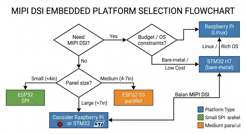
Voici le piège qui guette les ingénieurs novices : tous les microcontrôleurs et cartes de développement ne prennent pas en charge nativement le protocole MIPI. Si la spécification est séduisante sur le papier, la prise en charge matérielle est inégale en pratique. Cet article passe en revue trois plateformes qui dominent le marché de l’embarqué — STM32, Raspberry Pi et ESP32 — et vous explique clairement ce que chacune peut et ne peut pas faire avec une interface d’affichage MIPI. Sans détour, juste les réalités matérielles.
Contexte industriel : L’Alliance MIPI compte actuellement plus de 350 organisations membres. La spécification DSI 1.3 prend en charge des débits de voie D-PHY jusqu’à 2,5 Gbit/s par voie. Une liaison DSI typique à deux voies fonctionnant à 400 Mbit/s par voie offre environ 800 Mbit/s de bande passante utile pour l’affichage, ce qui est suffisant pour une résolution de 720p à 60 images par seconde avec une marge confortable.
STM32 : Du vrai matériel DSI, mais uniquement sur les puces appropriées
Les chips qui en sont réellement dotées
STMicroelectronics a commencé à intégrer un contrôleur hôte MIPI DSI dans certaines gammes STM32 vers 2014. STM32F469/F479 fut la première apparition grand public, suivie par STM32H747/H757 série à double cœur et le STM32H7BxToutes ces puces embarquent un hôte DSI sur puce conforme à la spécification MIPI DSI version 1.01 et prennent toutes en charge jusqu'à deux voies de données D-PHY.
Qu'est-ce que cela signifie concrètement ? Sur le STM32H747, avec les deux voies DSI fonctionnant à 400 Mbps, on atteint un débit total de 800 Mbps, suffisant pour gérer sans problème une dalle 480 × 854 à 60 Hz en 24 bits. La carte d'évaluation STM32H747I-DISCO de ST est livrée avec une telle dalle déjà montée, ce qui permet de vérifier facilement si le problème vient du routage DSI de votre carte ou du firmware.
Le périphérique hôte DSI prend en charge les deux Mode vidéo (flux continu de pixels, similaire à HDMI) et Mode de commande (Modèle d'écriture dans la mémoire tampon d'image, largement utilisé dans les écrans AMOLED). Le mode de commande est particulièrement utile pour le développement de produits alimentés par batterie : l'écran gère sa propre mémoire tampon d'image et se rafraîchit automatiquement, permettant ainsi au microcontrôleur de se mettre en veille entre les mises à jour d'affichage. Ce seul mécanisme peut réduire significativement la consommation d'énergie de l'écran.
Le Driver Stack en langage clair
La bibliothèque HAL de ST inclut un module dédié stm32h7xx_hal_dsi.c gérant l'initialisation de l'hôte, la configuration des modes vidéo/commande et la signalisation d'erreurs de base. Dans la plupart des projets concrets, il est également nécessaire d'écrire une séquence d'initialisation de l'écran : une liste de paquets DCS (Display Command Set) envoyés via la liaison DSI en mode basse consommation avant le passage au flux vidéo haute vitesse. Les circuits intégrés d'affichage courants, tels que l'OTM8009A et le NT35510, disposent de séquences d'initialisation de référence dans les exemples de firmware CubeH7 de ST.
La partie la plus délicate concerne l'agencement du circuit imprimé. La note d'application AN4860 de ST est une lecture indispensable : les paires D-PHY nécessitent une impédance différentielle contrôlée de 100 Ω, des stubs courts et un découplage approprié à proximité des broches DSI. Les ingénieurs qui négligent ce document et s'étonnent ensuite des scintillements ou des pannes de leur écran à des débits élevés le regrettent presque toujours.
Matrice de compatibilité STM32 MIPI DSI
Remarque : L’interface DSI est absente de la grande majorité des microcontrôleurs STM32. Les STM32G0, L4, F0, F1, F3 et la plupart des variantes F4 en sont dépourvus. Pour ces microcontrôleurs, les options d’interface d’affichage sont le SPI (adapté aux petits écrans, mais limité à environ 10-20 images/s pour les résolutions supérieures à 320 × 240) ou le RGB parallèle LTDC sur les modèles F4xx/H7xx qui en sont équipés.
Raspberry Pi : la porte d’entrée la plus simple pour le développement MIPI DSI
Aperçu du matériel
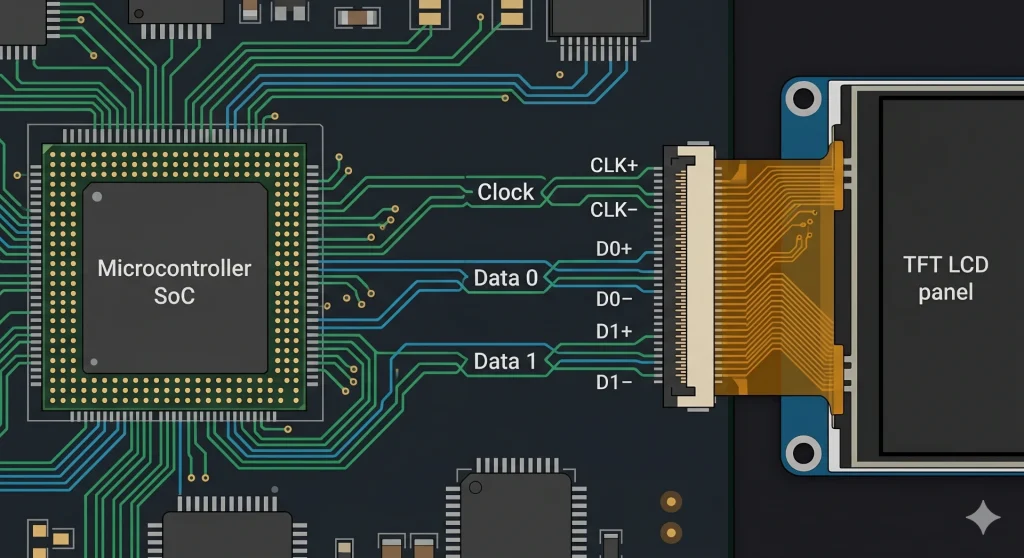
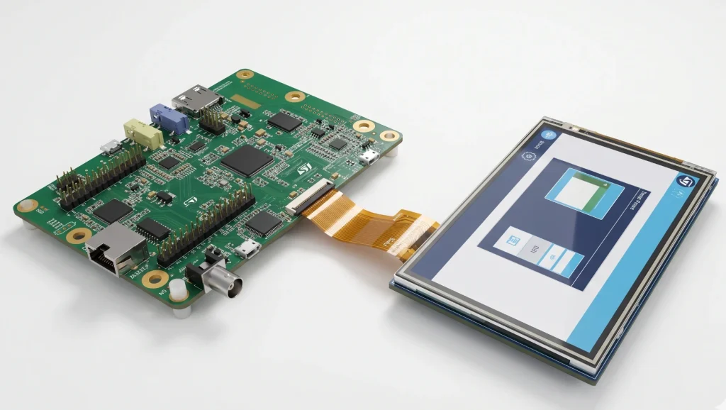
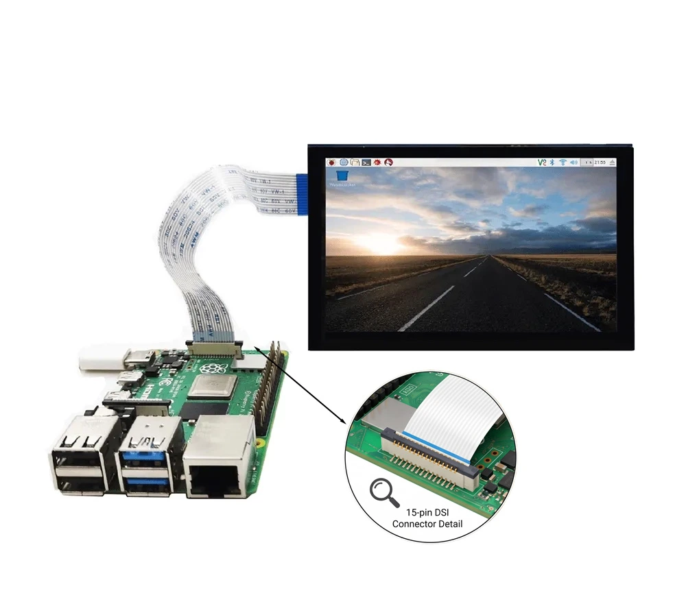
Depuis le modèle B+ original, chaque Raspberry Pi de taille standard est livré avec un Connecteur DSI FPC à 15 broches Sur la carte, on trouve le connecteur « DISPLAY », une caractéristique constante des Raspberry Pi 2, 3, 4 et maintenant Pi 5. Les Pi Zero et Zero 2 W utilisent un connecteur FPC 22 broches plus étroit, électriquement similaire mais physiquement différent, ce qui peut induire en erreur lors de l'achat de câbles d'affichage.
Le Broadcom BCM2711 intégré au Pi 4 pilote ce connecteur avec un émetteur MIPI DSI à 2 voies. La conception de référence — l'écran tactile officiel Raspberry Pi de 7 pouces — fonctionne à environ 200–285 Mbps par voie selon le mode d'affichage, ce qui est largement dans la plage de fonctionnement confortable du D-PHY. Raspberry Pi 5 Le plus intéressant, c'est que sa puce pont sud RP1 personnalisée offre deux ports DSI indépendants, chacun capable de gérer deux voies à des vitesses suffisantes pour une sortie 1080p60. Il s'agit d'une véritable amélioration pour quiconque conçoit des systèmes de bornes interactives à double affichage ou des panneaux industriels haute résolution.
Côté logiciel : Linux simplifie tout
C’est là que le Raspberry Pi justifie pleinement sa réputation de plateforme MIPI DSI la plus conviviale pour les développeurs. Grâce à son système Linux complet, la prise en charge des écrans est assurée par le sous-système drivers/gpu/drm/panel/ du noyau. L’ajout d’un nouvel écran se résume à écrire une superposition d’arbre de périphériques (Device Tree) déclarant le canal DSI, les timings de l’écran et la séquence d’initialisation, ainsi que – si le circuit intégré de l’écran n’est pas encore pris en charge par le noyau Linux – un petit module noyau.
Pour la plupart des modules d'affichage MIPI DSI disponibles dans le commerce, de 3,5 à 10 pouces, un pilote fonctionnel (surcouche ou pilote externe) existe déjà au sein de la communauté. Comparez cela à l'environnement STM32 « bare metal », où chaque octet de la séquence d'initialisation doit être écrit manuellement : la différence de productivité est flagrante. La pile Linux du Raspberry Pi permet également d'utiliser n'importe quel framework d'interface graphique : Qt, GTK, Electron, LVGL avec DRM, voire un navigateur web en plein écran.
Produit associé : Écrans pour Raspberry Pi — Écran Kadi — Une gamme sélectionnée de modules d'affichage MIPI DSI et SPI vérifiés pour Raspberry Pi, allant de 3,5 à 10,1 pouces avec option tactile capacitive.
Pièges liés aux connecteurs et limites des câbles
Deux points posent souvent problème aux débutants en conception d'écrans pour Raspberry Pi. Premièrement, le brochage : le Pi 4 utilise un FPC à 15 broches, la broche 1 étant la plus proche du bord de la carte, tandis que le Pi 5 utilise le même connecteur physique, mais avec une affectation de signal légèrement différente sur les ports DSI plus récents. Il est donc essentiel de toujours vérifier les spécifications du câble lors du passage d'une génération de Pi à une autre. Deuxièmement, la longueur du câble. L'interface MIPI DSI D-PHY a été conçue pour l'interconnexion au niveau de la carte, et non pour le câblage externe. La grande majorité des modules d'affichage compatibles sont livrés avec des câbles de 100 à 200 mm. Au-delà de 300 mm, l'intégrité du signal commence à se dégrader aux débits élevés, ce qui peut entraîner des artefacts visuels ou des coupures de liaison. Si votre application nécessite un écran plus éloigné du Pi, une configuration à une voie et à vitesse réduite avec un câble plus court est souvent un choix plus judicieux que de faire passer deux voies à 500 Mbps dans un câble de 400 mm.
L'ESP32-P4 est le seul ESP32 doté d'une interface MIPI DSI native ; tous les autres utilisent des interfaces SPI/QPI, parallèle 8080 ou RGB.
Les limites (et le point de basculement)
Soyons clairs : avant l’arrivée de l’ESP32-P4, aucune puce de la famille ESP32 (qui comprend l’ESP32 d’origine, le S2, le S3, le C3, le C6 et le H2) n’intégrait d’émetteur MIPI DSI. Espressif a conçu ces composants pour la connectivité sans fil et les charges de travail générales des microcontrôleurs, et non pour les pipelines d’affichage à large bande passante. De ce fait, les interfaces d’affichage disponibles pour l’ensemble de la gamme ont toujours été limitées à quelques options anciennes et moins performantes.
Voici ce que vous obtenez réellement avec les pièces non-P4 :
- Interfaces SPI et QPI : présentes sur presque toutes les variantes d’ESP32. Elles conviennent aux petits écrans basse résolution, mais le débit de pixels atteint rapidement sa limite.
- Interface parallèle 8080 : C’est la meilleure interface disponible sur un ESP32-S3. Elle intègre un contrôleur LCD parallèle 16 bits (protocole Intel 8080 ou Motorola 6800) fonctionnant en pratique à environ 20 MHz. Le débit brut atteint ainsi environ 320 Mbit/s, une valeur qui paraît correcte jusqu’à ce qu’on la compare à celle du MIPI DSI. Une seule voie de données DSI, fonctionnant à un débit conservateur de 250 Mbit/s, offre déjà une bande passante utile supérieure pour les pixels, et le DSI peut gérer jusqu’à quatre voies, contrairement au bus parallèle.
- Interface RGB : Également présente sur des puces comme la S3, mais elle consomme toujours beaucoup de broches et manque de l’efficacité série de la DSI.
La limitation de la bande passante se manifeste clairement au niveau de la fréquence d'images. Prenons l'exemple d'un ESP32-S3 pilotant un écran RGB 800×480 en 16 bits via l'interface parallèle. Grâce au DMA qui gère le flux de pixels et au processeur qui n'intervient pas, on peut espérer environ 30 à 40 images par seconde. C'est parfaitement suffisant pour des interfaces utilisateur statiques, la navigation dans les menus ou un tableau de bord de capteurs à mise à jour lente. Mais dès qu'on ajoute des animations plein écran ou du contenu vidéo, l'expérience devient rapidement saccadée.
Puis vint l'ESP32‑P4.
L'ESP32-P4 change complètement la donne. C'est le premier — et à ce jour le seul — ESP32 doté d'une interface MIPI DSI native intégrée. Cet ajout propulse l'écosystème ESP32 dans l'ère des écrans modernes, permettant de piloter directement des dalles de qualité smartphone et tablette, avec une bande passante et une fluidité d'affichage inégalées par les interfaces parallèles et SPI. Si votre projet requiert la prise en charge native de MIPI DSI, l'ESP32-P4 est actuellement la seule option au sein de la famille ESP32.
Solution de contournement pour le circuit intégré de pont
Si vous avez absolument besoin d'un panneau MIPI DSI sur un ESP32 (par exemple, parce que le panneau que vous avez choisi ne possède qu'une interface DSI), la solution technique standard est un pont ICLe composant le plus souvent mentionné est le SSD2828, un convertisseur RGB vers DSI monopuce. L'ESP32 (ou tout autre microcontrôleur) pilote le SSD2828 via SPI pour le configurer, puis lui fournit un flux vidéo RGB parallèle. Le SSD2828 convertit ce flux en une sortie MIPI DSI compatible avec l'écran. Cela fonctionne. Cependant, cela augmente le coût de la nomenclature, la surface du circuit imprimé et la complexité du firmware ; il s'agit donc d'un compromis qu'il convient d'évaluer soigneusement par rapport au simple choix d'un autre écran doté d'une interface native compatible.
Une approche plus simple et plus courante pour les produits basés sur l'ESP32 consiste à choisir d'emblée un module LCD TFT doté d'une interface SPI. Les contrôleurs de panneau comme le ILI9341, ST7789, ILI9488, et GC9A01 Ces modules sont disponibles de 1,3 à 4 pouces et sont parfaitement compatibles avec le composant esp_lcd d'ESP-IDF et les bibliothèques Arduino de la communauté. À une résolution de 320 × 240 et à 60 images par seconde, le protocole SPI à 40 MHz est largement suffisant. À partir de 480 × 320, on observe une baisse de la fréquence d'images ; à partir de 800 × 480, l'interface parallèle ou un autre SoC est fortement recommandé.
Produit associé : Solutions d'affichage intégrées — Kadi Display — Modules d'affichage de qualité industrielle avec interfaces SPI, parallèle et DSI adaptés aux conceptions embarquées basées sur ESP32 et STM32.
Comparaison côte à côte : Aperçu de la prise en charge MIPI de la plateforme
Choisir le bon module d'affichage pour votre configuration
Si vous utilisez STM32 H7 ou F469
Optez pour MIPI DSI. Le matériel est disponible, les pilotes HAL sont éprouvés et le gain en nombre de broches par rapport à un panneau RGB parallèle 24 bits est considérable : moins de pistes, des connecteurs plus petits et une gestion des interférences électromagnétiques simplifiée. Privilégiez les circuits intégrés de panneau dotés de jeux de commandes DCS standard (OTM8009A, NT35510 et RM67162 sont tous documentés dans les exemples CubeH7 de ST) afin de ne pas avoir à repartir de zéro pour la séquence d'initialisation.
Si vous utilisez un Raspberry Pi 4 ou 5
MIPI DSI est le choix idéal. Branchez un câble FPC compatible, flashez le pilote approprié, et l'écran apparaîtra comme un framebuffer Linux standard. Pour les projets nécessitant un second écran, le Raspberry Pi 5 peut gérer simultanément deux écrans DSI via ses deux ports indépendants — une fonctionnalité qui requérait auparavant une carte d'extension coûteuse ou un circuit intégré de pilotage externe.
Recommandé: Présentoir Kadi — Catalogue complet des produits — Panneaux MIPI DSI pour Raspberry Pi, modules TFT LCD industriels pour STM32, écrans AMOLED et barres, et personnalisation OEM. Fabricant basé à Shenzhen avec plus de 20 ans d'expérience.
Si vous êtes sur ESP32
Soyez réaliste quant à la résolution et à la fréquence d'images cibles avant de choisir un écran. Si votre interface utilisateur tient dans une résolution de 320×240 ou 480×320, un écran SPI bien choisi est simple et économique. Si vous avez besoin d'une résolution de 800×480 avec une fréquence d'images acceptable, l'interface LCD parallèle de l'ESP32-S3 est la solution idéale. Par ailleurs, demandez-vous si l'ESP32 est toujours le SoC le plus adapté : un Raspberry Pi CM4 ou un STM32H7 pourraient mieux convenir à votre projet, plutôt que de devoir composer avec une limite de bande passante d'affichage.
L'avenir de l'industrie : DSI-2, AMOLED et automobile
L'Alliance MIPI n'est pas restée inactive. MIPI DSI-2 Ajoute la prise en charge des couches physiques C-PHY et A-PHY en plus de la couche D-PHY existante. La couche C-PHY, en particulier, offre une meilleure densité de données par paire de broches, un atout majeur lorsque le nombre de broches du connecteur est limité dans les conceptions compactes. Le débit d'une liaison C-PHY à une voie peut dépasser celui d'une liaison D-PHY à deux voies, ce qui est crucial pour les dispositifs portables ultra-fins et les écrans de tableaux de bord automobiles où chaque millimètre de section de câble compte.
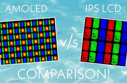
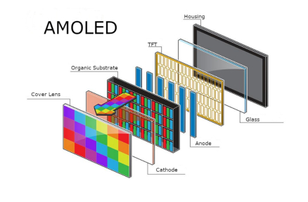
Sur le marché des panneaux photovoltaïques lui-même, Affichages AMOLED Les technologies AMOLED se diffusent des smartphones haut de gamme vers l'électronique grand public de milieu de gamme et, de plus en plus, vers les applications industrielles et médicales. Le mode Command de l'AMOLED, où la dalle stocke sa propre mémoire tampon d'images et se rafraîchit automatiquement, est parfaitement adapté aux systèmes embarqués alimentés par batterie, car il permet au SoC hôte de se mettre en veille entre les mises à jour de l'interface utilisateur sans que l'écran ne s'éteigne. Les fabricants d'écrans comme Affichage Kadi Nous proposons désormais des modules AMOLED dans des formats adaptés à l'intégration, ce qui permet de spécifier facilement l'AMOLED dans une interface homme-machine industrielle sans programme de développement de panneau personnalisé.
Pour les applications automobiles, la spécification MIPI A-PHY (Automotive PHY) s'impose : elle étend l'écosystème MIPI aux liaisons d'affichage embarquées jusqu'à 15 mètres à 16 Gbit/s, avec des fonctions de sécurité intégrées. Bien que cela dépasse largement le cadre des projets amateurs utilisant des microcontrôleurs STM32 ou Raspberry Pi, cette spécification illustre la direction que prend le secteur de l'affichage embarqué.
Réflexions finales
Trois plateformes, trois expériences d'affichage MIPI bien distinctes. La série STM32 H7 offre une véritable interface DSI intégrée, directement sur le matériel : puissante et compacte, elle vous permet de contrôler l'intégralité du pilote. Le Raspberry Pi propose une interface DSI native, avec un écosystème Linux prenant en charge la majeure partie du traitement : le chemin le plus rapide, du matériel à l'affichage fonctionnel, et de loin. L'ESP32 n'offre ni l'une ni l'autre, mais ce n'est pas forcément un problème si vous êtes réaliste quant à la taille de l'écran et la fréquence d'images dès le départ.
L'erreur la plus coûteuse dans la conception d'écrans embarqués ne réside pas dans le choix du matériel, mais dans une inadéquation des attentes. Choisir une dalle MIPI DSI 1080p et découvrir ensuite que le microcontrôleur sélectionné ne prend pas en charge le protocole MIPI est une situation frustrante et évitable. Consacrez dix minutes à l'étude des spécifications d'interface avant de commander des échantillons ; le reste du projet s'en trouvera considérablement simplifié.
Pour des recommandations de modules d'affichage adaptés à vos projets (MIPI DSI pour Raspberry Pi, écrans LCD TFT industriels pour STM32 ou panneaux SPI pour ESP32), consultez la gamme complète sur kadidisplay.com. L'équipe prend également en charge les projets d'affichage personnalisés OEM et ODM avec des délais de livraison courts depuis son site de Shenzhen.
Avertissement : Toutes les marques et tous les noms de produits sont des marques déposées de leurs propriétaires respectifs. Les données techniques proviennent de fiches techniques, de manuels de référence et de la documentation des fabricants accessibles au public. Cet article ne constitue pas une déclaration officielle de STMicroelectronics, Raspberry Pi Ltd. Espressif Systèmes, ou l'Alliance MIPI. Liens internes vers les produits : kadidisplay.com.
Précédent
Guide de sélection de l'interface d'affichage
Suivant
Interface d'affichage MIPI dans les systèmes LCD industriels
Laisser un commentaire

Derniers blogs et nouvelles
- MIPI DSI Display Compatibility Checklist: 10 Specifications to Match with Your Host Processor Before Ordering
- How to Calculate MIPI DSI Bandwidth and Data Rate per Lane for an Embedded Display
- Why Does an LVDS Display Flicker in Industrial Equipment? Causes and Design Checks
- MIPI DSI Display Not Turning On: Interface, Driver and Initialization Checks for Embedded HMI
- How to Choose Display Interfaces for Rugged Industrial HMI and Panel PC Projects