Huis
-
Blog & Nieuws
-
MIPI DSI Display Works at Room Temperature but Fails After Warm-Up: A Troubleshooting Workflow
MIPI DSI Display Works at Room Temperature but Fails After Warm-Up: A Troubleshooting Workflow
2026-09-18
00:00
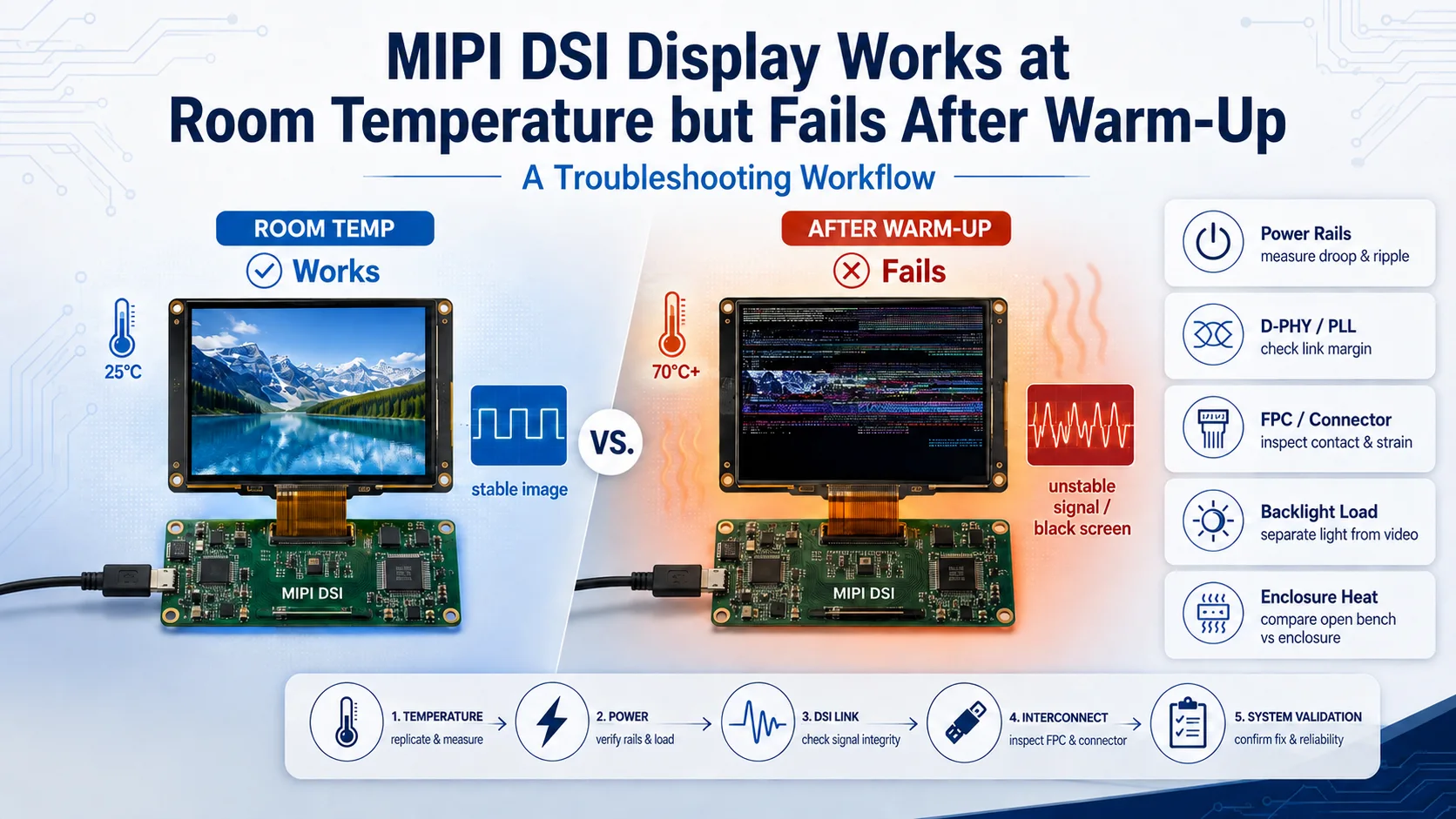
When a MIPI DSI display fails after warm-up but operates correctly at room temperature, temperature may be exposing a marginal power, D-PHY, FPC, connector, or system-cooling condition. It does not automatically mean the LCD has exceeded its temperature limit. First separate image loss from backlight, touch, host, and warm-reboot failures. Then correlate the failure time with measured temperatures, panel-side power rails, DSI error status, backlight load, and enclosure conditions before changing the display module or hardware.
First Confirm That This Is a Warm-Up Failure
A display that goes black after 30 minutes may be experiencing a temperature-related failure, but elapsed time alone is not proof. A scheduled software event, host thermal throttling, suspend sequence, regulator fault, or backlight protection state can produce a similar symptom.
Document exactly what fails:
-
Does the image disappear while the backlight remains on?
-
Does the backlight turn off while touch remains responsive?
-
Does image corruption appear before the screen goes black?
-
Does the touch controller also disconnect?
-
Does the host continue operating, throttle, or restart?
-
Does the display recover after cooling, after a software restart, or only after complete power removal?
Also distinguish continuous warm-up from a warm reboot. A reboot may leave rails charged, preserve bootloader state, or use a different reset and initialization path. That belongs primarily to startup sequencing, which is covered in the MIPI DSI power sequencing and reset timing guide.
Ambient temperature, enclosure air temperature, panel temperature, and regulator temperature are different measurements. Record them separately where accessible and safe to measure.
Run Quick Checks Before Changing Hardware
Begin with the known working configuration. Keep the firmware, resolution, timing, pixel format, DSI mode, and lane count unchanged while testing one system variable at a time.
Reduce backlight brightness while leaving the DSI configuration unchanged. If the time to failure increases, investigate backlight power, regulator loading, and enclosure heat. This result does not prove that the backlight is defective; it may simply be the largest adjustable thermal or electrical load.
Next, compare open-bench operation with the production-intent enclosure. Use the same host board, power source, FPC, software, and display settings. If the system fails only when enclosed, inspect heat-source placement, airflow, bracket conduction, internal temperature, and cable routing.
Where the panel and host documentation permit it, compare an allowed lower DSI workload, such as a lower refresh rate. Improved stability can indicate reduced link margin or power loading, but it is a diagnostic clue rather than an approved production fix.
Before applying localized heat or cooling, use controlled methods appropriate for the components and their specifications. An unrecorded heat-gun test can exceed component limits, move connectors, or create a thermal gradient that does not represent the device application.
Use a Fault Tree to Select the Next Measurement
| Observation | First area to investigate | Next controlled check |
|---|---|---|
| Lower brightness extends operating time | Backlight load, power, and heat | Compare current, rails, and temperature at fixed brightness levels |
| Image corrupts before going black | D-PHY margin, lane rate, FPC, or connector | Read host link errors and test an allowed lower workload |
| Backlight turns off but touch remains active | LED driver or backlight protection | Check LED rail, enable, PWM, and driver status |
| Touch works but the image disappears | DSI link, panel rails, PLL, or panel state | Capture DSI status, clocks, reset, and panel-side supplies |
| The complete system resets | Host power or thermal protection | Review system logs, regulator state, and processor temperature |
| Failure occurs only in the final enclosure | System thermal design | Compare open and enclosed operation with identical settings |
| Cooling restores the image without reboot | Temperature-dependent margin | Correlate recovery with temperature, rails, and link status |
| Recovery requires complete power removal | Reset, discharge, or fault recovery | Compare shutdown, discharge, and reinitialization behavior |
The table identifies where to look first. It does not replace the exact panel, host-controller, regulator, connector, and backlight documentation.
Build a Controlled Time-Temperature-Load Test
Record the Operating Point and Failure Timeline
Record the complete display configuration together:
-
Active resolution and full horizontal and vertical timing
-
Refresh rate and transported pixel format
-
Video or command mode
-
Active data lanes and requested lane rate
-
Host board, panel, FPC, and connector revisions
-
OS, BSP, kernel, driver, and Device Tree versions
-
Backlight brightness, current-control method, and PWM state
For each run, record the time from power-on to the first image symptom and complete failure. Add ambient temperature, accessible panel and PCBA temperatures, host thermal state, and enclosure condition. A test record is more useful when another engineer can reproduce the same operating point.
Kadi’s MIPI DSI bring-up checklist provides the wider evidence chain for power, reset, PHY state, lanes, initialization, video timing, and backlight. For warm-up troubleshooting, capture those same signals over time rather than only during startup.
Capture Electrical and Software Evidence at Failure
Measure relevant rails at the panel connector where practical. A regulator output can look stable at its source while cable resistance, connector contact, filtering, or load creates a different waveform at the module.
Compare voltage, ripple, droop, reset, panel enable, backlight enable, and PWM before and during the failure. Review host status for PLL lock, lane state, timeout, ECC, CRC, or other controller-specific evidence. Register names and available diagnostics depend on the host platform.
Collect kernel, DRM, regulator, and thermal logs. If touch uses I2C or USB, record whether that interface remains active. A working touch path does not prove that DSI video is healthy, and a failed touch path does not prove that the image link has failed.
Identify the Root Cause Category
Power, Backlight, and Thermal Load
A regulator may operate acceptably when cold but lose sufficient margin as load and internal temperature increase. Voltage drop through an FPC or connector can make the panel-side condition different from the PCBA measurement.
High-brightness backlights increase electrical load and heat generation. The LED driver may also report or enter a protection state. Treat backlight operation separately from DSI: light without an image does not confirm video, while an unlit screen does not confirm that DSI has stopped.
D-PHY, PLL, FPC, and Connector Margin
A MIPI DSI link operating close to an endpoint or channel limit may become unreliable as electrical conditions change. Possible evidence includes image corruption, intermittent blocks, lane errors, timeouts, or sensitivity to lane rate and cable position.
Inspect the complete path: host routing, adapter PCBA, connector, FPC, and panel input. Thermal expansion, connector contact, FPC strain, and an enclosure-imposed bend can expose an interconnect problem that does not appear during an open bench test.
Host, Driver, and Enclosure Behavior
A host can change operating behavior as it heats. Check processor throttling, display-clock configuration, regulator events, and driver recovery rather than assuming that the panel caused the failure.
Sealed housings, nearby processors, backlight circuits, and brackets can create local hotspots. The final thermal path should be assessed as part of the display stack, including the touch module, PCBA, mechanical support, and enclosure.
Choose the Correct Fix
Adjust software or parameters when measured evidence shows a marginal clock, unsupported operating point, incorrect recovery path, or configuration that can be corrected within both endpoint specifications.
Replace the display module when its documented operating temperature, timing, lane-rate range, backlight, touch, or mechanical specifications do not meet the application. Kadi’s 10.1-inch MIPI DSI display for embedded SBCs is a relevant reference with published MIPI DSI, I2C touch, brightness, and operating-temperature information. Compatibility still depends on the exact host, DSI configuration, power, connector, software, and mechanical design.
Modify the FPC or connector when the fault follows cable routing, contact, strain, length, or temperature. Revise the PCBA when power delivery, the backlight driver, PLL behavior, connector placement, routing, or component cooling is responsible. Change the structure when the enclosure, bracket, sealing, or heat-source placement creates an unacceptable thermal condition.
Confirm Compatibility at Four Levels
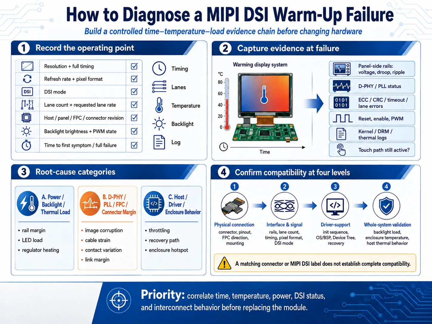
A replacement display should be checked at four separate levels:
-
Physical connection: connector, pitch, pinout, FPC direction, module outline, and mounting.
-
Interface and signal: power rails, lane count, mapping, timing, pixel format, DSI mode, and lane-rate range.
-
Driver support: initialization, reset sequence, OS/BSP, Device Tree, and fault recovery.
-
Whole-system validation: backlight load, touch, FPC route, enclosure temperature, host thermal behavior, and intended operating conditions.
A matching connector, resolution, or MIPI DSI label does not establish complete compatibility.
Select the Appropriate Solution Level and Prepare the RFQ
A standard Touch Display Module may fit when its documented optical, electrical, thermal, and mechanical specifications match the project. A modified module may be more appropriate when the application needs a different backlight, FPC, connector, touch panel, cover lens, or bonding arrangement.
When the LCD, touch, PCBA, FPC, bracket, power, and thermal path must be coordinated, the project moves toward a Custom Display Assembly or Modular HMI Solution. Kadi weergave can be approached at the product or integration level, subject to specification review and project verification.
For a useful RFQ, include the host platform, board revision, current module specification, resolution, complete timing, DSI mode, lane count, lane rate, backlight configuration, touch interface, operating-temperature requirement, and software versions. Add FPC, PCBA, and enclosure drawings, the time-to-failure record, measured temperatures, available logs or waveforms, failure photos, application, and projected quantity.
Conclusie
A MIPI DSI display that fails after warm-up should be diagnosed as a Complete Display System before any single component is blamed. Correlate time, temperature, power, DSI status, backlight load, interconnect behavior, and enclosure conditions, then choose the smallest change supported by evidence.
To discuss the next step, contact met Kadi Display with the host platform, display specification, DSI settings, power and backlight arrangement, operating-temperature target, enclosure drawing, failure timeline, logs, and failure photos.
Veelgestelde vragen
Why does a MIPI DSI display recover after cooling down?
Cooling may restore electrical, power, connector, or D-PHY margin. Recovery identifies a temperature correlation, but measurements are still needed to determine whether the panel, host, power path, interconnect, or enclosure is responsible.
Does a black screen after warm-up mean the LCD is overheating?
Not necessarily. A black screen can result from backlight shutdown, panel power loss, DSI link errors, host throttling, PLL behavior, or driver recovery. Check image, backlight, touch, and host operation separately.
Can lowering the refresh rate fix the problem?
A lower refresh rate can reduce DSI workload and may improve stability, making it useful for diagnosis. It is an acceptable final setting only if it meets the application and remains within the documented operating conditions of both endpoints.
Should I select a wide-temperature display module?
Select one when its documented operating range and other specifications match the application. A wide-temperature module does not correct an unsuitable regulator, marginal FPC, incompatible host, or enclosure with inadequate heat management.
What evidence should be sent with an RFQ?
Send the host and module specifications, DSI timing and lane configuration, power and backlight design, operating-temperature target, FPC and enclosure drawings, software versions, failure timeline, measured temperatures, logs, photos, application, and projected quantity.
Voorgaande
Niet meer
Volgende
How to Choose an LCD Controller Board: Architecture, EDID, Timing and Latency
Laat een reactie achter

Laatste Blog & Nieuws
- MIPI DSI Display Works at Room Temperature but Fails After Warm-Up: A Troubleshooting Workflow
- How to Choose an LCD Controller Board: Architecture, EDID, Timing and Latency
- Industrial Display RFQ Checklist: Build a Supplier-Ready Evidence Package
- Industrial LCD Drop-In Replacement Checklist: From Hard Stops to Release Evidence
- MIPI DSI in Industrial LCD Displays: What Engineers Should Know
Gerelateerde Blog & Nieuws