




Huis
-
Blog & Nieuws
-
PCAP Touch Works on the Bench but Fails After Metal Enclosure Assembly: An Isolation Checklist
PCAP Touch Works on the Bench but Fails After Metal Enclosure Assembly: An Isolation Checklist
2026-09-11
00:00
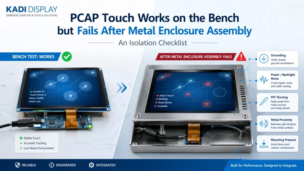
When a touchscreen fails in a metal enclosure but works on the bench, the enclosure has introduced one or more new electrical or mechanical variables. Likely suspects include an altered ground reference, power or backlight noise, FPC routing, metal near the sensor, and mounting pressure. Do not replace the touch panel immediately. Reassemble the unit in controlled stages, change one variable at a time, and identify the exact step that causes unresponsive touch, ghost inputs, dead zones, or coordinate drift.
What Changed Between the Bench Test and the Enclosed Unit?
A successful bench test confirms that the touch module can operate in one configuration. It does not validate the final device. Once installed, the same module may encounter a metal bezel, grounded bracket, production power supply, backlight converter, compressed gasket, bent FPC, or different cable route.
Document both configurations before testing. Record the display and touch-module part numbers, touch controller, I2C or USB interface, power source, backlight state, firmware, cover-lens construction, and mounting arrangement. Define the failure precisely: complete loss of touch, intermittent disconnection, ghost touch, coordinate drift, or an edge-specific dead zone.
The most useful question is not simply “Does it work?” It is “At which assembly step does its behavior change?”
For the broader relationship between the display, touch panel, cables, PCB, and housing, review Kadi Display’s industrial display stack-up design guide.
Run Quick Isolation Checks Before Changing Hardware
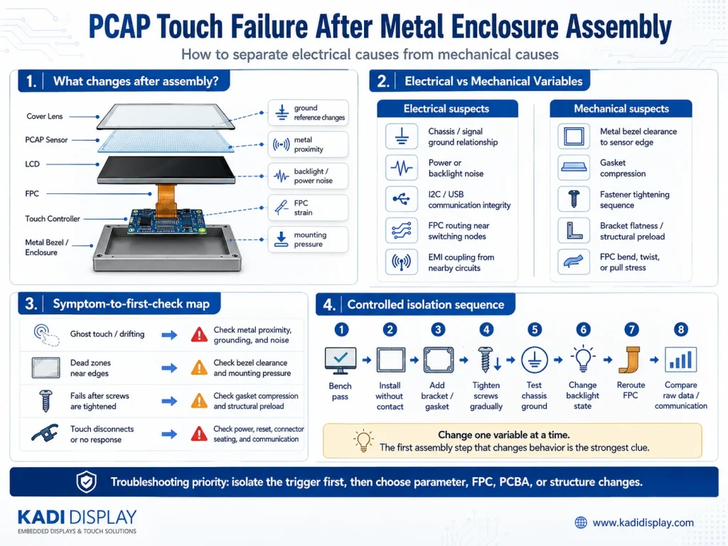
Start with the known working bench configuration and add production parts one at a time:
-
Place the module near the enclosure without making mechanical or electrical contact.
-
Insert it into the enclosure without installing the gasket or screws.
-
Add the bracket and gasket without fully tightening the fasteners.
-
Tighten fasteners in a documented sequence.
-
Test the intended chassis-ground connection.
-
Compare operation with the backlight off, at fixed current, and under its normal PWM setting.
-
Move the touch FPC away from the LED driver, DC/DC converter, display cable, and other switching paths.
-
Compare touch-controller communication and raw data after every step, where the platform exposes them.
A temporary floating or grounded configuration may help isolate a variable, but it is not automatically an acceptable production fix. The released ground arrangement must be evaluated with the actual PCBA, enclosure, shielding, and applicable system requirements.
Use a Fault Tree to Identify the First Suspect
The observed trigger should determine the next test.
| Observation | First area to investigate | Next controlled check |
|---|---|---|
| Touch changes as metal approaches the sensor | Metal proximity and ground reference | Compare separated, installed-floating, and intended-ground states |
| Errors follow backlight brightness or PWM | Power and switching-noise coupling | Hold mounting constant and compare backlight operating states |
| Moving the FPC changes the problem | FPC routing or connector contact | Reposition the tail without changing firmware or ground |
| Failure starts after screws are tightened | Gasket compression or structural preload | Loosen fasteners in a controlled sequence |
| I2C or USB communication disappears | Power, reset, connector, interface, or driver | Check supply, reset, enumeration, bus errors, and cable seating |
| Communication remains but coordinates become unstable | Sensor noise, metal proximity, or tuning | Compare baseline and raw touch data between assembly states |
This workflow prevents an electrical symptom from being misclassified as a defective sensor. It also prevents a pressure-induced problem from being treated only with controller tuning.
Test Electrical and Mechanical Variables Separately
Electrical Tests: Ground, Power, Interface, and Noise Sources
Map the relationships among chassis ground, PCBA signal ground, the LCD frame, the touch-controller ground, and any cable shield. A metal enclosure can change sensor capacitance and high-frequency return paths. A floating frame, unintended multiple ground paths, or a noisy connection may each produce different symptoms.
Check the touch supply at the controller during operation, not only with the unit idle. Record reset and interrupt behavior, I2C errors, or USB disconnects. If available, capture controller baseline, raw-signal, and noise values before and after installation.
Repeat the comparison while changing only the backlight state. LED boost converters, PWM edges, power cables, and display-interface routing can couple noise into the touch sensor or FPC. Keep the touch tail away from switching nodes during the isolation test.
Do not assume that connecting every metal part to signal ground will correct the problem. The appropriate chassis, shield, and signal-ground relationship depends on the system architecture and should be checked against the controller, PCBA, and equipment design documentation.
Mechanical Tests: Bezel, Gasket, Fasteners, and FPC Strain
If the failure follows tightening or mechanical movement, inspect the complete stack rather than only the touchscreen.
Check the distance between the metal bezel and the sensor’s active and edge regions. Look for uneven gasket compression, warped brackets, incorrect boss height, hard contact around the cover lens, and fastener loads that distort the bonded assembly. Compare touch behavior as each fastener is tightened to the intended condition.
Inspect the FPC at the connector, stiffener transition, first bend, and enclosure edges. The final route should not twist the tail, pull on the connector, or press it against a sharp or noisy component. A cable that functions while flat on a bench may become unreliable when folded or trapped in the housing.
Confirm the Root Cause Before Selecting a Fix
A grounding or EMI-related root cause is more credible when the fault follows a repeatable electrical variable: enclosure ground state, backlight load, power source, cable position, or nearby switching circuit. A mechanical root cause is more credible when the behavior follows screw sequence, gasket compression, bracket position, or local pressure.
Controller settings can also matter. The final cover lens, sensor stack, surrounding metal, and noise environment may require configuration supported by the selected controller. Tuning may improve noise margin, glove response, or sensitivity, but it should not be used to conceal unstable power, incorrect grounding, damaged cables, or excessive structural preload.
Physical fit, electrical interface, driver support, and system validation must remain separate decisions. Two modules may have the same dimensions or both use I2C or USB while differing in pinout, controller, reset behavior, firmware requirements, sensor geometry, FPC direction, and mounting limits. Interface labels alone do not establish complete compatibility.
Choose the Correct Fix: Parameters, Module, FPC, PCBA, or Structure
Adjust controller parameters when communication is stable, the assembly is mechanically sound, and the controller documentation supports configuration for the final lens and noise environment.
Consider a different or modified Touch Display Module when the sensor geometry, controller, touch interface, cover-lens construction, or environmental requirement does not match the application. Kadi’s 12.1-inch optical-bonded CTP display is one relevant product reference with I2C and USB touch options. Its published configuration should not be generalized to unrelated hosts or enclosures.
Revise the FPC when tail length, exit direction, connector orientation, bending, or proximity to noise sources is the dominant constraint. Revise the PCBA when touch power, ground architecture, ESD protection, backlight conversion, connector placement, or routing creates the coupling path.
Change the mechanical design when metal clearance, gasket position, bracket flatness, fastener loading, or enclosure tolerances trigger the fault. When several of these elements are coupled, a custom display assembly may be more appropriate than repeatedly modifying a standard module.
Select the Appropriate Solution Level
A standard Touch Display Module is suitable when its published optical, electrical, touch, and mechanical specifications match the device. A modified module may be considered when the project needs a different cover lens, bonding method, FPC, connector, or touch-interface arrangement.
A Custom Display Assembly becomes relevant when the LCD, touch sensor, cover glass, bonding, FPC, PCBA, and mounting parts need coordinated definition. A Modular HMI Solution is the next level when the display, touch input, controller board, power arrangement, and mechanical installation must operate as a defined subsystem.
Kadi weergave can be approached at the product or project level. The suitable scope depends on the selected host, drawings, interface requirements, enclosure design, and verification plan.
Prepare an RFQ for an Enclosure-Related Touch Problem
Include the current LCD and touch-module specifications, touch controller, I2C or USB interface, host platform, operating system, display size, resolution, brightness, cover-lens and bonding requirements, and operating temperature.
Also provide the FPC and enclosure drawings, connector and PCBA locations, grounding diagram, backlight and power arrangement, gasket and bracket design, and the assembly step that triggers the failure. Photos or videos of both configurations, communication errors, and available touch raw data can make the initial review more specific. Include the application and expected quantity for quotation context.
Conclusie
A bench-pass, enclosure-fail touchscreen should be treated as an integration problem until controlled testing proves otherwise. Isolate metal proximity, grounding, power noise, FPC routing, and mounting pressure before selecting a corrective action.
To discuss the appropriate product or integration level, contact met Kadi Display with the module specification, host and touch interface, enclosure and FPC drawings, grounding arrangement, operating conditions, and failure photos. The next step may be a parameter review, a modified module, a custom assembly, or a broader HMI integration evaluation.
Veelgestelde vragen
Can a metal bezel cause ghost touch or dead zones?
It can alter the electric field around a PCAP sensor, particularly near its edges. The result depends on bezel distance, sensor construction, ground reference, cover lens, controller configuration, and the assembled system. Test metal proximity separately from mounting pressure.
Should the LCD frame and metal enclosure be connected to ground?
They may require an intentional grounding or bonding strategy, but there is no universal connection method. Define chassis, shield, signal-ground, LCD-frame, and touch-controller references for the actual PCBA and enclosure, then verify touch, ESD, and noise behavior.
Can optical bonding solve an enclosure-related touch failure?
Optical bonding changes the optical and mechanical stack and may support certain environmental requirements. It does not by itself correct a noisy power supply, unsuitable grounding, poor FPC routing, controller incompatibility, or excessive mounting pressure.
When should the touch controller be retuned?
Consider tuning after confirming stable power and communication, correct grounding, acceptable metal clearance, and a mechanically controlled assembly. Use settings supported by the controller documentation and verify them in the production-intent enclosure.
What information is needed to evaluate a replacement touchscreen?
Provide the display and touch specifications, controller and interface, host platform, cover-lens and bonding requirements, FPC and connector drawings, enclosure stack-up, ground and power arrangement, operating environment, failure evidence, application, and expected quantity.
Voorgaande
MIPI DSI vs LVDS vs RGB vs eDP: Which Interface Is Best for Industrial Displays?
Volgende
MIPI DSI Works at Low Refresh Rates but Fails at 60 Hz: A Practical Troubleshooting Workflow
Laat een reactie achter

Laatste Blog & Nieuws
- Industrial LCD EOL: What Happens from Pre-Announcement to Replacement Mass Production?
- Electronic Component Obsolescence Management for Industrial Displays: An OEM Guide
- How to Develop a Production Ready Custom Display Assembly TFT Module Touch Cover Glass FPC Bonding and Mounting
- 15 Pin vs 22 Pin Raspberry Pi DSI Connectors Cable Pinout and Compatibility
- Native MIPI DSI vs LVDS or HDMI Bridge: An OEM Display Architecture Decision Guide

