Interface de exibição MIPI em sistemas LCD industriais
2026-04-29
10:18
Interface de exibição MIPI em sistemas LCD industriais
Guia Prático para Engenheiros sobre DSI, Seleção de PHY, Layout de PCB e Implantação de IHM no Mundo Real
Por Equipe Técnica da Kadi Display | www.kadidisplay.com
Dos smartphones às fábricas: a jornada inesperada do MIPI
Eis algo que raramente aparece em análises de fichas técnicas: a interface que roda dentro do visor do seu painel de PLC industrial quase certamente começou sua vida útil como uma especificação para um celular Nokia ou Samsung. Isso não é uma crítica — na verdade, é por isso que funciona tão bem.
A MIPI Alliance foi fundada em 2003. Os membros fundadores — Arm, Nokia, STMicroelectronics e Texas Instruments — tinham um objetivo específico e prático: impedir que cada fabricante de celulares criasse seu próprio barramento interno para conectar processadores a sensores de câmera e telas. Essa fragmentação estava custando dinheiro a todos. Em 2005, a primeira especificação da DisplaySerial Interface (DSI) foi lançada. Em 2010, ela já estava presente em praticamente todos os smartphones comercializados. Em 2015, os designers industriais começaram a dar mais atenção à tecnologia.
O que possibilitou essa convergência? Alguns fatores ocorreram. As exigências das interfaces homem-máquina (IHM) nas fábricas começaram a demandar resoluções que o RGB paralelo simplesmente não conseguia fornecer com rapidez suficiente, sem transformar as placas de circuito impresso em verdadeiros emaranhados de conectores de 40 pinos. Os equipamentos de imagem médica necessitavam de um controle de interferência eletromagnética (EMI) mais rigoroso. Os projetistas de cockpits automotivos queriam posicionar as telas mais distantes do SoC — às vezes ocupando todo o painel da porta. A física subjacente do MIPI acabou se mostrando exatamente o que todos os três setores precisavam, embora nunca tenha sido projetada com eles em mente.
Este guia explica como funciona o MIPI. display interface Funciona de verdade — as opções da camada física (PHY), o que elas significam em um layout de PCB real, como a inicialização do CI do driver costuma dar errado e o que considerar antes de especificá-la para seu próximo produto industrial ou médico. Também abordaremos onde o LVDS legado ainda faz sentido, porque a resposta honesta é: às vezes faz.
Se você está começando do zero na seleção de uma interface de exibição, confira a visão geral da Kadi Display em Escolhar o melhor visor para seu dispositivo incorporado Este guia aborda a árvore de decisão mais ampla antes de entrar nos detalhes específicos do MIPI.
O básico: o que o MIPI DSI realmente faz
MIPI DSI — Display Serial Interface — é uma ligação serial ponto a ponto. Um transmissor (seu SoC), um receptor (seu CI de driver de tela). Só isso. Sem arbitragem de barramento, sem meio compartilhado. Os dados fluem em uma única direção para o conteúdo dos pixels, com um caminho de retorno de baixa velocidade para reconhecimento de comando e dados de toque em algumas configurações.
A ligação é construída a partir de canais. Cada canal é um par diferencial: dois condutores, sinais com polaridades opostas e cancelamento de ruído integrado à sua estrutura física. Um desses canais é dedicado ao clock. Os restantes transportam dados. A maioria dos painéis industriais que você encontrará utiliza dois ou quatro canais de dados; existem configurações de canal único, mas atingem um limite de aproximadamente 1080×1920 a 60 Hz, e você atingirá esse limite mais rapidamente do que imagina se adicionar qualquer compressão.
Dois modos regem a forma como o SoC se comunica com o painel. Modo de vídeo É o método mais simples: o host transmite continuamente dados de pixels, quadro a quadro, como uma varredura raster de um monitor CRT antigo. O painel não possui memória própria — ele simplesmente exibe o que recebe. A maioria dos monitores industriais de alta taxa de atualização funciona dessa maneira. Modo de comando É diferente: o painel possui um buffer de quadros integrado. O SoC envia atualizações somente quando algo realmente muda na tela, permitindo que o painel se atualize automaticamente. Para um painel de controle que exibe principalmente valores de processo estáticos com alertas ocasionais, o modo de comando pode reduzir substancialmente o consumo de energia da interface — às vezes pela metade ou mais.
Para uma análise mais aprofundada do protocolo em nível de pacote — como os pacotes curtos e longos são estruturados, qual a aparência da máquina de estados da interface — vale a pena ler a análise técnica de Kadi: Interface Serial de Exibição MIPI (DSI) — Detalhes do Protocolo.
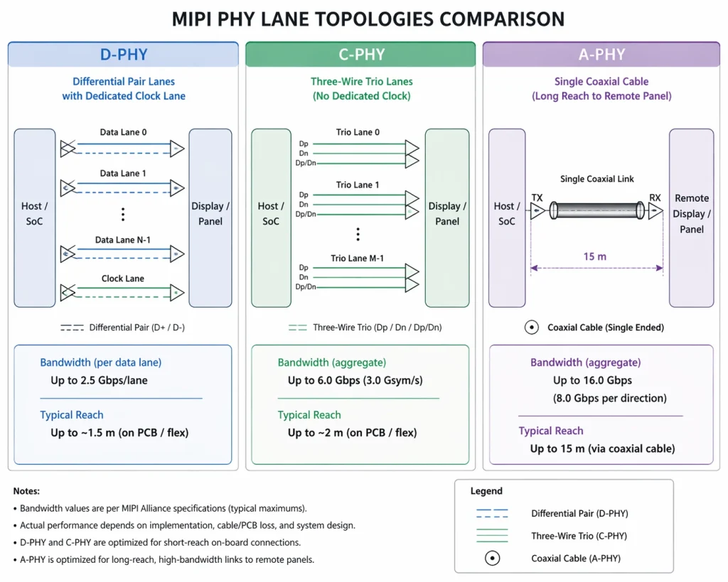
Escolhendo uma camada física: D-PHY, C-PHY e A-PHY
É aqui que os engenheiros costumam se confundir, porque 'MIPI' e 'D-PHY' são usados como sinônimos na maioria das especificações de produtos — mas não são a mesma coisa. D-PHY é a camada física mais comum, sim. Mas não é a única opção, e as diferenças entre as três camadas físicas disponíveis são bastante importantes dependendo do que você está desenvolvendo.
D-PHY: Aquele que você usará 90% das vezes.
O D-PHY utiliza sinalização diferencial padrão com uma via de clock dedicada. A oscilação de tensão é baixa — em torno de 200 mV — o que explica, em parte, a menor radiação em comparação com o LVDS. As taxas de dados aumentaram ao longo das sucessivas revisões da especificação: a versão 1.2 atingiu o pico de 2,5 Gbps por via (10 Gbps agregados em quatro vias), a versão 2.1 elevou esse valor para 6,5 Gbps por via e a versão 3.5 introduziu um modo de clock embutido que liberou a via de clock para dados.
Para a maioria dos painéis industriais de 7 a 10,1 polegadas com resolução de 1280×800 ou 1920×1200 a 60 Hz, o D-PHY v1.2 ainda é perfeitamente adequado. Você não precisa da versão 2.1, a menos que esteja trabalhando com resolução 4K ou altas taxas de quadros. Optar pela especificação mais recente quando chips mais antigos suportam a versão 1.2 nativamente apenas aumenta a complexidade de inicialização sem nenhum ganho.
O comportamento do gerenciamento de energia é importante na prática. O D-PHY alterna entre o modo de alta velocidade (HS, para dados de pixel) e o modo de baixo consumo (LP, para sinalização de controle e ociosidade de canal). Cada transição leva algumas centenas de nanossegundos. Para vídeo contínuo, isso é imperceptível; para telas em modo de comando que enviam pequenas atualizações frequentes, o tempo pode se acumular, e alguns circuitos integrados de driver lidam com a transição de LP para HS de forma mais eficiente do que outros. Vale a pena consultar a folha de dados do seu painel antes de presumir que o modo de comando funcionará da maneira esperada.
C-PHY: Quando a EMI é a restrição
C-PHY é a opção da qual ninguém fala até estar em um teste de pré-conformidade EMC, presenciando uma falha Classe 5 da norma CISPR 25 que não conseguem explicar. Em vez de pares de fios, o C-PHY usa trios de fios — três condutores por canal, com codificação de símbolos trifásica. Cada transição de símbolo carrega aproximadamente 2,28 bits, resultando em mais dados por ciclo de clock. O efeito colateral é que a energia espectral é distribuída de forma mais uniforme entre as frequências, em vez de se concentrar na frequência fundamental do clock. É isso que ajuda a reduzir a EMI.
O C-PHY v2.0 pode atingir uma taxa agregada de 44,5 Gbps, o que é suficiente para 8K não comprimido. Na prática, o uso industrial do C-PHY é principalmente em imagens médicas — monitores de tomografia computadorizada, consoles de ultrassom, sistemas de visualização cirúrgica onde o monitor é montado a centímetros de equipamentos de radiofrequência de alta frequência e a lista de materiais regulamentar não permite muita massa de blindagem. Se você não estiver nessa situação, o D-PHY é mais simples de implementar.
A-PHY: Resolvendo o problema do comprimento do cabo
Tanto o D-PHY quanto o C-PHY têm um alcance de cabo limitado a aproximadamente um metro. Isso é adequado para um tablet ou um terminal portátil. No entanto, não é adequado para um grande centro de usinagem CNC, onde o painel de exibição é parafusado à estação do operador a 3 metros do painel de controle, ou para o painel de um caminhão, onde a tela principal fica a 2 metros do controlador de domínio. Historicamente, essas implementações exigiam chips de ponte SerDes proprietários — custo adicional, latência adicional e itens adicionais na lista de materiais.
A-PHY elimina a necessidade dessas pontes. É um serializador/desserializador de longo alcance, especificado para até 15 metros, operando a até 32 Gbps de downlink (v2.0) em cabo coaxial padrão ou cabo de par trançado blindado. O caminho de uplink — para toque, feedback háptico e metadados da câmera — opera a até 1,6 Gbps. A especificação da taxa de erro de pacotes é 10⁻¹⁹, que é excepcionalmente agressivo; ele é calibrado para aplicações críticas de segurança, onde um pixel corrompido em um visor de aviso constitui um incidente regulatório.
A-PHY é a base física da estrutura MIPI Automotive SerDes Solutions (MASS), que adiciona camadas de segurança funcional ISO 26262 e proteção de conteúdo HDCP. Se você estiver projetando displays de painel de instrumentos ou interfaces homem-máquina (IHM) para veículos, esta é a arquitetura que você precisa entender. Para sistemas embarcados em geral, a Guia de masterização MIPI DSI Aborda como essas escolhas da camada física (PHY) se conectam ao projeto real do sistema.
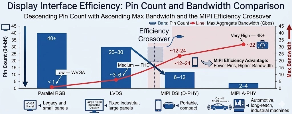
Como o MIPI DSI se compara ao LVDS e ao RGB paralelo na prática
Antes de prosseguirmos com a implementação, vale a pena sermos diretos sobre onde cada interface realmente se encaixa — porque os materiais de marketing do MIPI tendem a fazer o LVDS parecer obsoleto, e isso não é totalmente preciso.
O RGB paralelo é realmente obsoleto para qualquer resolução acima de WVGA. A quantidade de pinos é incontrolável, os requisitos de distorção em altas frequências exigem camadas de PCB que você preferiria não usar, e o consumo de energia é constante, independentemente do conteúdo. Se você estiver herdando um projeto que o utiliza, considere a possibilidade de redesenhar. Se você estiver começando do zero e, por algum motivo, estiver considerando essa opção: não faça isso.
LVDS é uma história diferente. Para telas na faixa de 10 a 21 polegadas — monitores industriais, painéis de imagens médicas, terminais de ponto de venda — LVDS ainda é uma escolha racional, principalmente se o seu SoC ou FPGA tiver suporte robusto para saída LVDS e você não precisar da largura de banda para 4K. O alcance de 10 metros do cabo é realmente útil, o ecossistema é amplo e o processo de inicialização é bem compreendido. As desvantagens em termos de consumo de energia e espaço na placa de circuito impresso são reais, mas não tornam o LVDS automaticamente a escolha errada para equipamentos industriais fixos, onde nenhum desses fatores representa uma restrição rígida.
Onde o MIPI DSI claramente se destaca: equipamentos portáteis, dispositivos alimentados por bateria, qualquer aplicação onde o tamanho da placa de circuito impresso seja importante, qualquer dispositivo com resolução 4K e qualquer linha de produtos onde se deseje aproveitar a mesma propriedade intelectual (IP) do SoC de tela tanto em uma variante para o consumidor quanto em uma variante industrial.
Layout de PCB: Onde as implementações MIPI realmente falham
Se você conversar com engenheiros que já trabalharam com hardware MIPI DSI, a discussão sobre o que deu errado quase sempre acaba voltando para a placa de circuito impresso (PCB). O protocolo em si é bastante simples. A inicialização do circuito integrado do driver é gerenciável. O problema está no layout — e há mais deles do que os documentos de especificação costumam enfatizar.
O controle de impedância é imprescindível.
Com 2,5 Gbps por canal, suas trilhas diferenciais são linhas de transmissão. Elas se comportam como linhas de transmissão. Ignore esse fato e você terá reflexões — que se manifestam como erros de pixel, jitter e falhas intermitentes de sincronização, que são exasperantes de depurar porque geralmente dependem da temperatura e da carga. A meta é uma impedância diferencial de 100 Ω, ±10%. Isso é mais preciso do que parece, considerando as tolerâncias típicas de fabricação de PCBs, e significa que você precisa especificar explicitamente a estrutura de camadas e a geometria das trilhas com o fabricante da placa, e não deixar isso como uma suposição.
Um detalhe que costuma chamar a atenção dos projetistas: o cálculo da impedância diferencial muda quando o cabo passa por cima de lacunas no plano de terra. Também muda quando o cabo passa perto de uma ilha de energia. Planeje a estrutura de camadas antes de rotear as vias MIPI, não depois.
Correspondência de comprimento e o que isso realmente significa
As faixas precisam ter o mesmo comprimento — a instrução comum é "dentro de 5 mils". Isso é verdade, mas o requisito menos mencionado é que as duas faixas dentro de cada par diferencial Também precisam ser compatíveis. O desvio intrapar costuma ser pior do que o desvio interfaixas na prática, porque os projetistas se preocupam excessivamente em manter a faixa de clock com o mesmo comprimento das faixas de dados, mas deixam as trilhas P e N de um único par se distanciarem devido a uma curva ou uma transição de via. O sintoma é uma tela sutilmente corrompida que funciona perfeitamente em bancada, mas falha em temperatura de operação ou sob vibração.
Vias, conectores e o plano de aterramento
Cada via em suas trilhas MIPI representa uma descontinuidade de impedância. Minimize-as. Quando não for possível evitar uma transição de via — por exemplo, uma mudança de camada em um conector — adicione vias de aterramento ao redor de cada via de sinal. A corrente de retorno precisa de um caminho de baixa impedância e, sem as vias de aterramento, ela encontrará um em outro lugar, criando uma antena de loop.
Os conectores FPC são outro ponto de falha comum. A interface de contato no conector normalmente quebra a geometria de impedância controlada. Algumas famílias de conectores lidam melhor com isso do que outras. Verifique as especificações de perda de inserção do seu conector na frequência de sinalização real, não apenas em CC.
Inicialização do circuito integrado do driver: o que as folhas de dados não te contam
MIPI DSI não é plug-and-play. Parece óbvio quando se diz, mas surpreende genuinamente os engenheiros com experiência em HDMI ou DisplayPort. Não há detecção de conexão a quente, negociação de EDID ou descoberta automática de modo. O SoC host precisa saber — precisamente — os parâmetros de temporização que seu painel específico exige e precisa enviar a sequência de comandos de inicialização do CI do driver na ordem correta antes de enviar os dados de pixel. Se qualquer um desses passos estiver errado, você não obtém nada: um painel em branco, uma exibição intermitente ou (raramente) um painel que liga, mas renderiza incorretamente.
Os três circuitos integrados de driver que aparecem com mais frequência em painéis industriais de 5 a 10 polegadas são: ILI9881C (comum em painéis de 720p com orientação retrato), o EK79007 (padrão para módulos de paisagem de 1024×600 e 1280×800), e o ST7701S (Amplamente difundidos em formatos quadrados e pequenos displays industriais). Os três são bem documentados, e os três apresentam peculiaridades em suas sequências de inicialização que não são bem documentadas.
Algumas coisas que vale a pena saber com base na experiência de criação de filhos:
- O tempo de resposta do sinal de reinicialização do painel é quase sempre mais curto do que o indicado na folha de dados. Se o seu visor piscar durante a inicialização, mas funcionar normalmente após a ativação, verifique se a duração do pulso de reinicialização e o atraso antes do primeiro comando DSI atendem às especificações mínimas — e então adicione uma margem de segurança.
- A estrutura de drivers DRM/KMS do Linux é o caminho certo para qualquer SoC executando Linux mainline. Escrever um driver de framebuffer do zero é desnecessário e cria um fardo de manutenção a longo prazo. O driver do painel (para o CI do driver) e o driver de host DSI (para o controlador do SoC) são módulos separados. Muitos SoCs industriais — NXP i.MX série 8, Rockchip RK3566, Allwinner H6 — possuem drivers de host DSI upstream. Seu trabalho geralmente se resume ao driver do painel, o que significa acertar a sequência de inicialização e os parâmetros de temporização.
- Se você estiver usando uma plataforma baseada em Raspberry Pi, a inicialização do MIPI DSI possui seu próprio fluxo de trabalho específico de sobreposição de árvore de dispositivos. Kadi Displays Guia passo a passo para conexão DSI no Raspberry Pi Este artigo aborda o assunto em detalhes práticos, incluindo a sintaxe de sobreposição e erros comuns de configuração.
- Os parâmetros de temporização — hsync/vsync, front porch, back porch, largura de pulso — devem corresponder precisamente aos requisitos do CI do driver do painel. Esses valores são fornecidos pelo fabricante do painel. Se você estiver usando um módulo Kadi Display, eles estão na folha de dados do produto. Se você estiver adquirindo os painéis de forma independente, considere a especificação de temporização do fabricante como uma restrição rígida, não uma sugestão.
Para uma análise técnica completa do DSI em nível de protocolo — máquina de estados, tipos de pacotes, gerenciamento de canais — o Visão geral da interface MIPI DSI É uma referência útil antes de se aprofundar no assunto da criação de filhos.
Requisitos ambientais para implantações industriais
Os componentes eletrônicos de consumo são mantidos em ambientes com temperatura controlada. Os componentes eletrônicos industriais, não. Um módulo de display MIPI que funciona perfeitamente em um laboratório a 25 °C precisa continuar funcionando em uma câmara fria a −20 °C, na lateral de uma máquina de embalagem onde a carcaça atinge 60 °C, em um terminal de navegação marítima com alta volatilidade de umidade e — para aplicações automotivas — em toda a faixa de temperatura estendida de −40 °C a +85 °C.
A própria interface não apresenta comportamento dependente da temperatura que cause problemas — os parâmetros de temporização do D-PHY são especificados com margem suficiente para as faixas de temperatura industriais. As limitações vêm do painel LCD, do circuito integrado do driver e do conjunto de retroiluminação. Painéis de nível industrial usam misturas de cristal líquido com menor variação de viscosidade em função da temperatura, evitando a resposta lenta ou os artefatos ópticos que os painéis de consumo apresentam abaixo de 0 °C. A retroiluminação também precisa ser especificada para o ambiente térmico — a eficiência do LED diminui com a temperatura, e uma retroiluminação dimensionada para 1.000 nits a 25 °C pode apresentar desempenho inferior a −20 °C se o driver não estiver compensando.
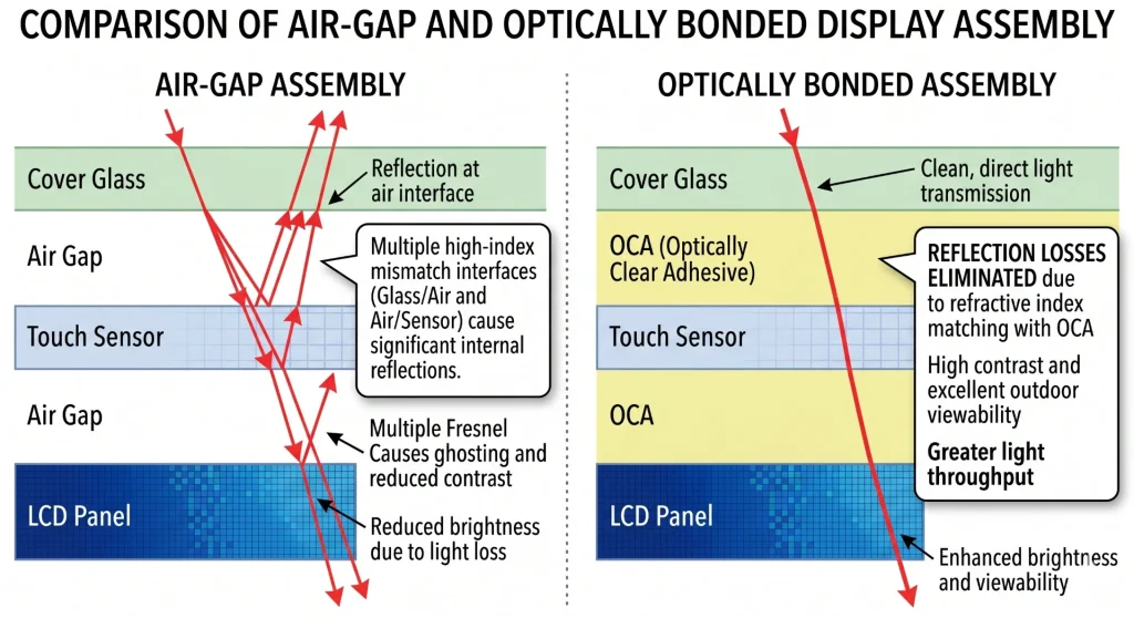
Colagem óptica e sua importância em aplicações reais
A colagem óptica — que consiste em colar o vidro de cobertura diretamente à face do painel LCD usando filme OCA ou resina OCR, eliminando o espaço de ar — não é apenas um recurso desejável para melhorar a legibilidade sob a luz solar. Em ambientes com variações de temperatura, a presença de um espaço de ar cria problemas de condensação: a umidade migra para o espaço e embaça a tela por dentro. Em ambientes com vibração, o espaço permite o movimento mecânico entre o vidro e o painel, o que eventualmente causa delaminação ou desvio na calibração do toque.
A melhoria na legibilidade proporcionada pela colagem óptica em condições de alta luminosidade ambiente é mensurável — estudos de campo mostram consistentemente uma melhoria de contraste de 30 a 40% sob luz solar direta em comparação com montagens com espaço de ar — mas o argumento da durabilidade é frequentemente o que realmente impulsiona a decisão para clientes industriais. A descrição técnica completa das opções de processo de colagem (OCR úmido, OCA/SOCA seco) é abordada no guia da Kadi Display. Colagem óptica — Como combinar um display com um painel sensível ao toque.
Para uma abordagem mais ampla sobre a seleção de telas para ampla faixa de temperatura, incluindo opções de mistura de cristais líquidos e considerações sobre o gerenciamento térmico da luz de fundo, consulte: Displays TFT de ampla faixa de temperatura para Aplicações industriais.
Onde o MIPI se encaixa nos segmentos de aplicação industrial
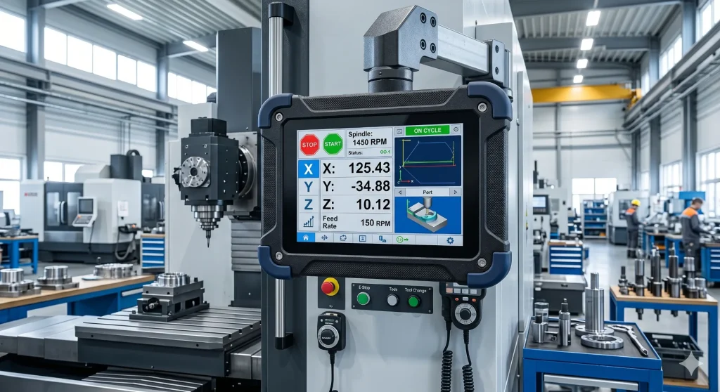
Automação de fábrica e IHM de processos
A maior parte das implementações industriais de MIPI consiste em painéis HMI: as telas de interface do operador em máquinas CNC, controladores de processo e estações de linha de montagem. Os tamanhos dos painéis nesse segmento variam principalmente de 7 a 10,1 polegadas. Os requisitos de resolução são de 800×480 para os mais básicos, 1280×800 para os mais comuns, e 1920×1200 para os de visualização de alta qualidade. As especificações de brilho para ambientes industriais normalmente começam em 800 nits e aumentam — a iluminação fluorescente no teto de uma fábrica é surpreendentemente brilhante, e os reflexos em um painel de baixo brilho em um ambiente de aço inoxidável representam um problema real de usabilidade.
A gama completa de considerações sobre displays HMI — tempo de resposta, tecnologia touchscreen, requisitos de ângulo de visão, especificações MTBF — é abordada em detalhes em: Como os monitores touchscreen de estrutura aberta são usados para automação de IHM industrialPara obter informações básicas sobre o que os sistemas HMI realmente fazem em um contexto de planta: O que é uma tela HMI? Usos comuns, tendências e o futuro da HMI.
Dispositivos médicos
Os requisitos para displays médicos impõem múltiplas restrições simultaneamente: segurança elétrica conforme a norma IEC 60601-1, conformidade com EMC em ambientes com alta densidade de equipamentos de radiofrequência, resistência química para protocolos de desinfecção e — para aplicações de diagnóstico — padrões de precisão de cores que excedem os requisitos industriais típicos. A interface MIPI DSI com C-PHY é particularmente adequada para aplicações médicas, pois o perfil de EMI é menor do que o da D-PHY com largura de banda equivalente, o que facilita a conformidade com a norma CISPR em ambientes com alta densidade de radiofrequência. A colagem óptica é praticamente padrão em equipamentos médicos portáteis: a vedação ambiental que ela proporciona contra umidade e produtos químicos de limpeza é tão importante quanto a melhoria óptica.
Displays automotivos e veiculares
É nas aplicações veiculares que a especificação A-PHY se destaca. A combinação dos requisitos de segurança funcional da ISO 26262, dos limites de EMC da CISPR 25, da ampla faixa de temperatura e da separação física entre os controladores de domínio e os painéis de exibição cria um conjunto de requisitos que nenhuma solução anterior à A-PHY atendia adequadamente sem hardware proprietário. Se você estiver projetando displays para painéis de instrumentos, telas sensíveis ao toque para consoles centrais ou sistemas de entretenimento para os bancos traseiros, vale a pena compreender o framework MASS desde o início da fase de arquitetura, e não como uma solução posterior.
Compressão de fluxo de exibição e direções futuras
À medida que as resoluções dos painéis aumentam, os requisitos de largura de banda bruta começam a exceder o que até mesmo o D-PHY com alta contagem de pistas pode fornecer sem recorrer ao C-PHY. Um painel 4K a 60 Hz em cores de 24 bits precisa de aproximadamente 14,9 Gbps de dados brutos de pixel. Isso equivale a quatro pistas do D-PHY v2.1 operando próximo à taxa máxima, sem margem para sobrecarga. A Compressão de Fluxo de Exibição (DSC), incorporada à especificação MIPI DSI-2 juntamente com o padrão VESA DSC, resolve esse problema reduzindo o volume de dados de 3 a 6 vezes, mantendo a qualidade da imagem visualmente sem perdas.
A tecnologia DSC permite que o conteúdo 4K seja executado em duas vias D-PHY em vez de quatro — o que tem efeitos diretos na complexidade da placa de circuito impresso (PCB), no tamanho do conector e no consumo de energia. A compressão é matematicamente sem perdas em termos de percepção visual; avaliações independentes mostram consistentemente que os fluxos comprimidos e não comprimidos por DSC são indistinguíveis para o olho humano em condições normais de visualização.
Além do DSC, duas tendências merecem atenção para aplicações industriais. Primeiro, a mudança para arquiteturas zonais em sistemas automotivos e industriais de alta tecnologia — onde um único controlador de domínio gerencia múltiplos fluxos de câmera e tela em uma infraestrutura comum de alta largura de banda — cria exatamente o cenário de implantação para o qual o A-PHY foi projetado. Segundo, o MIPI Touch está em desenvolvimento ativo: uma especificação para transportar dados de toque no mesmo link serial que os dados da tela, eliminando a fiação separada do controlador de toque I²C ou SPI que atualmente adiciona complexidade a cada IHM com toque capacitivo.
Perguntas Frequentemente Fazidas
P: MIPI DSI é mais difícil de implementar do que LVDS?
Sinceramente, sim — inicialmente. O LVDS tem um processo de inicialização mais simples e tolerâncias de layout de PCB mais flexíveis. O MIPI DSI exige um controle de impedância mais rigoroso, sequências de inicialização precisas do CI do driver e (no Linux) configuração correta da árvore de dispositivos. A vantagem é menor consumo de energia, maior largura de banda e uma área de PCB menor. Para equipes sem experiência prévia com MIPI, considere um ciclo de inicialização mais longo no primeiro projeto.
P: Posso usar o A-PHY em uma máquina industrial onde o visor está a 5 metros do controlador?
Sim, e provavelmente é a decisão certa. O A-PHY é especificado para 15 metros e elimina os chips de ponte SerDes proprietários que a mesma aplicação exigiria com o D-PHY. Os recursos de segurança funcional na estrutura MASS são opcionais se você não precisar de conformidade com a ISO 26262 — você pode implementar o A-PHY puramente pelos benefícios de alcance e largura de banda.
P: Quais circuitos integrados (CIs) de driver de painel são mais comuns em módulos MIPI industriais?
Para painéis de 5 a 7 polegadas, o ILI9881C (720p na vertical) e o ST7701S (formato pequeno/quadrado) são os mais comuns. Para painéis de 7 a 10,1 polegadas na horizontal, com resoluções de 1024×600 a 1280×800, o EK79007 domina o mercado. Todos os três possuem suporte robusto para drivers Linux. As sequências de inicialização variam entre lotes de alguns fornecedores — se você estiver adquirindo módulos em grande quantidade, solicite o dump dos registros de inicialização do seu lote específico.
P: A colagem óptica afeta o desempenho da interface MIPI?
Não há efeito direto na interface. A colagem óptica é uma técnica de montagem de telas que afeta o desempenho óptico, a durabilidade mecânica e a vedação ambiental. Ela não altera em nada o funcionamento das vias MIPI. Dito isso, a combinação de um painel MIPI de alto brilho com colagem óptica é essencialmente padrão para instalações industriais voltadas para o exterior ou com alta luminosidade ambiente — a interface e o método de montagem são partes complementares da mesma decisão de projeto. Mais detalhes em: O que é a ligação óptica? Um Guía para Mostras Industriais.
P: O MIPI DSI é compatível com o Raspberry Pi?
Sim — todos os modelos de Raspberry Pi, do Pi 1 ao Pi 5, incluem um conector DSI. O Pi 5 aprimorou significativamente o controlador host DSI. A inicialização requer configuração de sobreposição da árvore de dispositivos em vez de detecção plug-and-play. Kadi Displays Guia de conexão Raspberry Pi MIPI DSI Abrange todo o processo, incluindo a sintaxe específica da sobreposição e os modos de falha comuns.
Conclusão
A interface de tela MIPI não se tornou o padrão para sistemas LCD industriais por decisão própria. Ela chegou lá porque a física funcionou: baixa oscilação de tensão, dados serializados, rejeição diferencial de ruído e um roteiro de desenvolvimento da camada física (PHY) que acompanhou os requisitos de resolução e largura de banda. O fato de a indústria de dispositivos móveis já ter resolvido o problema da escala de produção — circuitos integrados de driver, blocos de IP de SoC, famílias de conectores — facilitou sua adoção em setores onde essas cadeias de suprimentos não existiam antes.
Na prática, trabalhar com MIPI DSI significa que o protocolo em si é gerenciável, mas os detalhes de implementação — layout da placa de circuito impresso, inicialização do circuito integrado do driver, configuração da árvore de dispositivos — exigem cuidado. Engenheiros que o tratam como uma interface plug-and-play pela primeira vez geralmente têm uma experiência ruim. Já aqueles que o abordam como um problema de linha de transmissão com um componente de inicialização por software conseguem fazê-lo funcionar de forma confiável.
Para projetos de produtos em que o orçamento de energia, o espaço na placa de circuito impresso e os requisitos de resolução tornam o MIPI a escolha lógica — o que abrange a maioria dos novos projetos de interfaces homem-máquina (IHM) industriais, dispositivos médicos e displays automotivos — vale a pena investir no rigor da implementação desde o início. Os ganhos são reais e sustentáveis ao longo do ciclo de vida do produto.
A linha completa de módulos LCD MIPI industriais da Kadi Display — incluindo painéis IPS de alto brilho, configurações com ligação óptica, variantes para ampla faixa de temperatura e integração personalizada de PCBA — está disponível em: www.kadidisplay.comPara dúvidas sobre especificações ou solicitações de desenvolvimento personalizado, a equipe técnica pode ser contatada diretamente pelo site.
Leitura complementar — Recursos técnicos do Kadi Display
- O que é MIPI DSI? Vantagens e Visão Geral Técnica
- Interface Serial de Display MIPI (DSI) — Referência de Protocolo
- Um guia passo por passo para masterizar a MIPI DSI
- Como conectar um display LCD de DSI MIPI a um Raspberry Pi
- O que é a porta MIPI DSI no Raspberry Pi?
- Colagem óptica — Como combinar um display com um painel sensível ao toque
- O que é a ligação óptica? Um Guía para Mostras Industriais
- Como os monitores de ecrã de toque aberto são usados para a Automatização Industrial da HMI
- Temperatura larga TFT mostra para aplicações industriais
- O que é uma tela HMI? Usos comuns, tendências e o futuro da HMI
- Monitores MIPI DSI de 7 polegadas: as melhores especificações em 2026
- Escolhar o melhor visor para seu dispositivo incorporado
PRIVENTE
Interface de exibição MIPI
NEXTO
Retenção versus Burn-in em telas LCD: Guia de Soluções e Prevenção para o Setor Industrial (Edição de 2026)
Deixe um comentário

Recent Blog & News
- MIPI DSI Display Compatibility Checklist: 10 Specifications to Match with Your Host Processor Before Ordering
- How to Calculate MIPI DSI Bandwidth and Data Rate per Lane for an Embedded Display
- Why Does an LVDS Display Flicker in Industrial Equipment? Causes and Design Checks
- MIPI DSI Display Not Turning On: Interface, Driver and Initialization Checks for Embedded HMI
- How to Choose Display Interfaces for Rugged Industrial HMI and Panel PC Projects